EP4391429A1 - Codierungsverfahren, decodierungsverfahren und zugehörige vorrichtung - Google Patents
Codierungsverfahren, decodierungsverfahren und zugehörige vorrichtung Download PDFInfo
- Publication number
- EP4391429A1 EP4391429A1 EP22868843.8A EP22868843A EP4391429A1 EP 4391429 A1 EP4391429 A1 EP 4391429A1 EP 22868843 A EP22868843 A EP 22868843A EP 4391429 A1 EP4391429 A1 EP 4391429A1
- Authority
- EP
- European Patent Office
- Prior art keywords
- lanes
- data
- processing
- data streams
- identifier
- Prior art date
- Legal status (The legal status is an assumption and is not a legal conclusion. Google has not performed a legal analysis and makes no representation as to the accuracy of the status listed.)
- Pending
Links
Images








Classifications
-
- H—ELECTRICITY
- H03—ELECTRONIC CIRCUITRY
- H03M—CODING; DECODING; CODE CONVERSION IN GENERAL
- H03M13/00—Coding, decoding or code conversion, for error detection or error correction; Coding theory basic assumptions; Coding bounds; Error probability evaluation methods; Channel models; Simulation or testing of codes
- H03M13/03—Error detection or forward error correction by redundancy in data representation, i.e. code words containing more digits than the source words
- H03M13/05—Error detection or forward error correction by redundancy in data representation, i.e. code words containing more digits than the source words using block codes, i.e. a predetermined number of check bits joined to a predetermined number of information bits
- H03M13/13—Linear codes
- H03M13/15—Cyclic codes, i.e. cyclic shifts of codewords produce other codewords, e.g. codes defined by a generator polynomial, Bose-Chaudhuri-Hocquenghem [BCH] codes
- H03M13/151—Cyclic codes, i.e. cyclic shifts of codewords produce other codewords, e.g. codes defined by a generator polynomial, Bose-Chaudhuri-Hocquenghem [BCH] codes using error location or error correction polynomials
- H03M13/1515—Reed-Solomon codes
-
- H—ELECTRICITY
- H04—ELECTRIC COMMUNICATION TECHNIQUE
- H04L—TRANSMISSION OF DIGITAL INFORMATION, e.g. TELEGRAPHIC COMMUNICATION
- H04L25/00—Baseband systems
- H04L25/02—Details ; arrangements for supplying electrical power along data transmission lines
- H04L25/14—Channel dividing arrangements, i.e. in which a single bit stream is divided between several baseband channels and reassembled at the receiver
-
- H—ELECTRICITY
- H04—ELECTRIC COMMUNICATION TECHNIQUE
- H04L—TRANSMISSION OF DIGITAL INFORMATION, e.g. TELEGRAPHIC COMMUNICATION
- H04L1/00—Arrangements for detecting or preventing errors in the information received
- H04L1/004—Arrangements for detecting or preventing errors in the information received by using forward error control
-
- H—ELECTRICITY
- H03—ELECTRONIC CIRCUITRY
- H03M—CODING; DECODING; CODE CONVERSION IN GENERAL
- H03M13/00—Coding, decoding or code conversion, for error detection or error correction; Coding theory basic assumptions; Coding bounds; Error probability evaluation methods; Channel models; Simulation or testing of codes
- H03M13/61—Aspects and characteristics of methods and arrangements for error correction or error detection, not provided for otherwise
- H03M13/611—Specific encoding aspects, e.g. encoding by means of decoding
-
- H—ELECTRICITY
- H04—ELECTRIC COMMUNICATION TECHNIQUE
- H04J—MULTIPLEX COMMUNICATION
- H04J3/00—Time-division multiplex systems
- H04J3/02—Details
- H04J3/04—Distributors combined with modulators or demodulators
- H04J3/047—Distributors with transistors or integrated circuits
-
- H—ELECTRICITY
- H04—ELECTRIC COMMUNICATION TECHNIQUE
- H04L—TRANSMISSION OF DIGITAL INFORMATION, e.g. TELEGRAPHIC COMMUNICATION
- H04L1/00—Arrangements for detecting or preventing errors in the information received
- H04L1/004—Arrangements for detecting or preventing errors in the information received by using forward error control
- H04L1/0041—Arrangements at the transmitter end
-
- H—ELECTRICITY
- H04—ELECTRIC COMMUNICATION TECHNIQUE
- H04L—TRANSMISSION OF DIGITAL INFORMATION, e.g. TELEGRAPHIC COMMUNICATION
- H04L1/00—Arrangements for detecting or preventing errors in the information received
- H04L1/004—Arrangements for detecting or preventing errors in the information received by using forward error control
- H04L1/0045—Arrangements at the receiver end
- H04L1/0047—Decoding adapted to other signal detection operation
-
- H—ELECTRICITY
- H04—ELECTRIC COMMUNICATION TECHNIQUE
- H04L—TRANSMISSION OF DIGITAL INFORMATION, e.g. TELEGRAPHIC COMMUNICATION
- H04L1/00—Arrangements for detecting or preventing errors in the information received
- H04L1/004—Arrangements for detecting or preventing errors in the information received by using forward error control
- H04L1/0056—Systems characterized by the type of code used
- H04L1/0057—Block codes
-
- H—ELECTRICITY
- H04—ELECTRIC COMMUNICATION TECHNIQUE
- H04L—TRANSMISSION OF DIGITAL INFORMATION, e.g. TELEGRAPHIC COMMUNICATION
- H04L1/00—Arrangements for detecting or preventing errors in the information received
- H04L1/004—Arrangements for detecting or preventing errors in the information received by using forward error control
- H04L1/0056—Systems characterized by the type of code used
- H04L1/0064—Concatenated codes
- H04L1/0065—Serial concatenated codes
-
- H—ELECTRICITY
- H03—ELECTRONIC CIRCUITRY
- H03M—CODING; DECODING; CODE CONVERSION IN GENERAL
- H03M13/00—Coding, decoding or code conversion, for error detection or error correction; Coding theory basic assumptions; Coding bounds; Error probability evaluation methods; Channel models; Simulation or testing of codes
- H03M13/25—Error detection or forward error correction by signal space coding, i.e. adding redundancy in the signal constellation, e.g. Trellis Coded Modulation [TCM]
-
- H—ELECTRICITY
- H03—ELECTRONIC CIRCUITRY
- H03M—CODING; DECODING; CODE CONVERSION IN GENERAL
- H03M13/00—Coding, decoding or code conversion, for error detection or error correction; Coding theory basic assumptions; Coding bounds; Error probability evaluation methods; Channel models; Simulation or testing of codes
- H03M13/29—Coding, decoding or code conversion, for error detection or error correction; Coding theory basic assumptions; Coding bounds; Error probability evaluation methods; Channel models; Simulation or testing of codes combining two or more codes or code structures, e.g. product codes, generalised product codes, concatenated codes, inner and outer codes
- H03M13/2906—Coding, decoding or code conversion, for error detection or error correction; Coding theory basic assumptions; Coding bounds; Error probability evaluation methods; Channel models; Simulation or testing of codes combining two or more codes or code structures, e.g. product codes, generalised product codes, concatenated codes, inner and outer codes using block codes
-
- H—ELECTRICITY
- H03—ELECTRONIC CIRCUITRY
- H03M—CODING; DECODING; CODE CONVERSION IN GENERAL
- H03M13/00—Coding, decoding or code conversion, for error detection or error correction; Coding theory basic assumptions; Coding bounds; Error probability evaluation methods; Channel models; Simulation or testing of codes
- H03M13/31—Coding, decoding or code conversion, for error detection or error correction; Coding theory basic assumptions; Coding bounds; Error probability evaluation methods; Channel models; Simulation or testing of codes combining coding for error detection or correction and efficient use of the spectrum
-
- H—ELECTRICITY
- H04—ELECTRIC COMMUNICATION TECHNIQUE
- H04B—TRANSMISSION
- H04B10/00—Transmission systems employing electromagnetic waves other than radio-waves, e.g. infrared, visible or ultraviolet light, or employing corpuscular radiation, e.g. quantum communication
- H04B10/50—Transmitters
- H04B10/516—Details of coding or modulation
-
- H—ELECTRICITY
- H04—ELECTRIC COMMUNICATION TECHNIQUE
- H04J—MULTIPLEX COMMUNICATION
- H04J3/00—Time-division multiplex systems
- H04J3/02—Details
- H04J3/06—Synchronising arrangements
- H04J3/0635—Clock or time synchronisation in a network
- H04J3/0685—Clock or time synchronisation in a node; Intranode synchronisation
- H04J3/0697—Synchronisation in a packet node
-
- H—ELECTRICITY
- H04—ELECTRIC COMMUNICATION TECHNIQUE
- H04L—TRANSMISSION OF DIGITAL INFORMATION, e.g. TELEGRAPHIC COMMUNICATION
- H04L1/00—Arrangements for detecting or preventing errors in the information received
- H04L2001/0092—Error control systems characterised by the topology of the transmission link
- H04L2001/0096—Channel splitting in point-to-point links
Definitions
- Embodiments of this application relate to the field of communication technologies, and specifically, to an encoding method, a decoding method, and a related apparatus.
- next-generation Ethernet technology with a throughput greater than 400 Gbps is needed to satisfy a bandwidth requirement of the future data center.
- FEC forward error correction
- a physical sublayer of the Ethernet communication architecture may be divided into a physical coding sublayer (physical coding sublayer, PCS), a physical medium attachment sublayer (physical medium attachment sublayer, PMA), and a physical media dependent (physical media dependent, PMD) sublayer.
- PCS physical coding sublayer
- PMA physical medium attachment sublayer
- PMD physical media dependent sublayer
- main data stream operations such as 64B/66B encoding processing, 256B/257B transcoding processing, alignment marker insertion processing, and Reed-Solomon (Reed-Solomon, RS) encoding processing are sequentially completed on data streams.
- RS Reed-Solomon
- data streams obtained through the RS encoding processing are distributed to physical coding sublayer lanes (PCS lanes), multiplex processing is performed by using a multiplexer (multiplexer, MUX), and then data streams obtained through the multiplex processing are sent to the PMA layer through m output lanes.
- PCS lanes physical coding sublayer lanes
- multiplex processing is performed by using a multiplexer (multiplexer, MUX)
- data streams obtained through the multiplex processing are sent to the PMA layer through m output lanes.
- operations such as clock and data recovery (clock and data recovery, CDR), transmitting-end bit multiplexing, and signal driving are performed on the received data streams.
- operations such as optical modulation and electrical-optical conversion of data are completed on data streams output from the PMA layer, and optical signals are output to a transmission medium, to complete an entire data operation at a transmitting end.
- the data streams are transmitted to the PMA layer of an optical module through the m output lanes at the PCS layer, and delay skew occurs between physical lanes.
- operations such as alignment, deskewing, and reordering of a plurality of physical coding sublayer lanes need to be completed, which has extremely great complexity and delay costs.
- the existing Ethernet communication architecture is applicable only to a scenario in which a throughput is within 400 Gbps.
- the existing Ethernet communication architecture cannot satisfy a system error correction performance requirement required by next-generation Ethernet communication with the throughput greater than 400 Gbps.
- Embodiments of this application disclose an encoding method, a decoding method, and a related apparatus, so as to separately perform inner-code encoding processing on each of z lanes of second data streams, without performing operations such as deskewing and reordering on the z lanes of second data streams, which reduces operation complexity and a delay.
- an embodiment of this application provides an encoding method.
- the encoding method may be applied to an optical module or another encoding apparatus.
- m lanes of first data streams are obtained through m input lanes, where m is a positive integer.
- the m lanes of first data streams are processed to obtain z lanes of second data streams, where z is a positive integer.
- Encoding processing is separately performed on each of the z lanes of second data streams to obtain z lanes of third data streams.
- Multiplex processing is performed on the z lanes of third data streams to obtain n lanes of fourth data streams, where n is a positive integer.
- each lane of second data stream may include Y to-be-encoded data blocks, and the to-be-encoded data block may be understood as a to-be-encoded information bit.
- a length of each to-be-encoded data block is k
- a parity bit length is p
- the length k of the to-be-encoded data block is 170 bits
- the total codeword length of the to-be-encoded data block is 180 bits after 10 parity bits are added.
- the length k of the to-be-encoded data block is 170 bits
- the total codeword length of the to-be-encoded data block is 179 bits after 9 parity bits are added.
- the total codeword length of the to-be-encoded data block is 181 bits after 11 parity bits are added.
- the length k of the to-be-encoded data block is 120 bits, the total codeword length of the to-be-encoded data block is 128 bits after 8 parity bits are added.
- inner-code encoding processing is separately performed on each of the z lanes of second data streams, and an FEC codeword in each third data stream obtained through encoding includes a boundary identifier.
- each of the z lanes of second data streams includes a to-be-encoded data block.
- encoding processing may be performed on the z lanes of second data streams in the following manner: performing inner-code encoding processing on a first data block to obtain one or more FEC codewords, where the first data block is at least C/z consecutive to-be-encoded data blocks in the corresponding second data stream, C is a positive integer, and C is an integer multiple of z.
- the encoding method further includes: inserting a first identifier at a position of a codeword boundary of any one of the FEC codewords, where the first identifier identifies the codeword boundary of the FEC codeword, and a throughput or a baud rate of an FEC codeword obtained through insertion of the first identifier is an integer multiple of a reference clock.
- the position of the codeword boundary may be understood as a codeword start and/or a codeword end. This is not limited herein.
- the codeword boundary of the FEC codeword is identified by the first identifier, so that a boundary position of each FEC codeword can be determined by directly identifying the first identifier in a subsequent decoding process, and a case in which inner-code decoding is ineffective in a case of the delay skew and an unknown data start position is avoided.
- each of the z lanes of second data streams includes a to-be-encoded data block.
- encoding processing may alternatively be performed on the z lanes of second data streams in the following manner: inserting a first identifier into each to-be-encoded data block in a first data block to obtain a second data block, where the first data block is at least C/z consecutive to-be-encoded data blocks in the corresponding second data stream; and performing encoding processing on the second data block to obtain an FEC codeword, where a throughput or a baud rate of the FEC codeword is an integer multiple of a reference clock.
- a codeword boundary of the FEC codeword obtained through encoding is identified by the first identifier, so that a boundary position of each FEC codeword can be determined by directly identifying the first identifier in a subsequent decoding process, and a case in which inner-code decoding is ineffective in a case of the delay skew and an unknown data start position is avoided.
- the first identifier is a preset identifier sequence.
- the first identifier may be a sequence consisting of" 1" and "0"
- a sequence such as "101010” or “1010” may be selected as the first identifier
- the first identifier may be another known sequence. This is not limited herein.
- the first identifier is set to be the preset identifier sequence, so that requirements in different scenarios can be satisfied.
- the first identifier is obtained based on a value of a first bit in the first data block, where the first bit is any one of at least one bit in the first data block; or the first identifier is obtained based on bit values of at least L second bits in the first data block, where there is an interval of s bits between every two adjacent second bits in the L second bits, L ⁇ 2, s ⁇ 0, and L and s are integers.
- the first bit may be the 0 th bit in the first data block. If a value of the 0 th bit is "0", the first identifier, that is, "1", may be obtained by directly performing a negation operation on the value of the 0 th bit.
- the first identifier may be obtained by directly performing a negation operation on the value of the 0 th bit.
- the first bit may alternatively be the 1 st bit, the 2 nd bit, or the like in the first data block. This is not limited herein.
- a codeword length of the first data block is 180 bits.
- a last bit may be selected for negation. That is, a value of the 179 th bit is selected to directly perform a negation operation, to obtain the first identifier.
- the first identifier is obtained by performing a negation operation on a bit at a start position or an end position of a codeword. This helps a receiving end quickly determine a codeword boundary.
- the four second bits selected from the first data block are the 0 th bit, the 2 nd bit, the 4 th bit, and the 6 th bit. In this way, bit values corresponding to the 0 th bit, the 2 nd bit, the 4 th bit, and the 6 th bit are processed through an exclusive OR operation, and a processing result may be used as the first identifier.
- the four selected second bits may alternatively be the 1 st bit, the 3 rd bit, the 5 th bit, and the 7 th bit; or the like. This is not limited herein.
- L may alternatively be 8, and s is 3; L is 6, and s is 4; or the like. In this application, neither a value of L nor a value of s is limited.
- the first identifier is determined based on the bit in the first data block. This can also be applicable to different scenarios.
- the m lanes of first data streams may be processed in the following manner to obtain z lanes of second data streams: performing demultiplex processing on the m lanes of first data streams based on a second ratio, to obtain the z lanes of second data streams, where the second ratio is a ratio of m to z.
- the second ratio is a ratio of m to z.
- 4:16 is merely used as an example for description.
- the second ratio may be another value. This is not limited in this application.
- demultiplex processing is directly performed on the m lanes of first data streams, to provide a plurality of possible implementations of obtaining the z lanes of second data streams.
- the performing demultiplex processing on the m lanes of first data streams based on a second ratio, to obtain the z lanes of second data streams includes: performing demultiplex processing on the m lanes of first data streams based on the second ratio, to obtain z lanes of fifth data streams; and separately performing Q-stage processing on each of the z lanes of third data streams to obtain the z lanes of second data streams, where each stage of processing in the Q-stage processing includes: performing round-robin distribution processing on a data stream obtained at a previous stage, to obtain at least two lanes of data substreams; performing delay processing on a first data substream to obtain a sixth data stream; and performing multiplex processing on a second data substream and the sixth data stream to obtain an output data stream obtained through current-stage processing, where the first data substream is at least one of the at least two lanes of data substreams, the second data substream is one lane of data substream that is in the at least two lanes of data substreams and on which delay
- a bit length of the sixth data stream is at least (N ⁇ Codeword length of an RS codeword)/(z ⁇ i) bits, where N is a positive integer, and i is a quantity of the data substreams.
- the encoding method further includes: obtaining m lanes of seventh data streams through the m physical lanes; and performing demultiplex processing on the m lanes of seventh data streams based on a second ratio, to obtain z lanes of eighth data streams; and the processing the m lanes of first data streams to obtain z lanes of second data streams includes: performing multiplex processing on the z lanes of second data streams and the z lanes of eighth data streams to obtain z second data streams obtained through the multiplex processing.
- the encoding method further includes: identifying an alignment marker in each lane of second data stream, where the alignment marker identifies a symbol boundary in the corresponding second data stream; and determining the symbol boundary in the corresponding second data stream based on the alignment marker.
- an AM alignment block of a 120-bit known sequence is added to each lane of first data stream, and there is a 48-bit common alignment marker in the AM alignment block of the 120-bit known sequence.
- locking and alignment may be implemented provided that the 48-bit common alignment marker is identified in an operation at a symbol boundary of the RS codeword.
- the m lanes of first data streams are obtained by performing, at a first ratio, multiplex processing on z lanes of data streams obtained through Reed-Solomon RS encoding.
- the first ratio may be understood as a ratio of z to m.
- the first ratio is 16:4, 32:4, 32:16, or 16:8. This is not limited herein.
- the m lanes of first data streams include N RS codewords in total, and each lane of first data stream may include (N ⁇ Codeword length of the RS codeword)/m bits.
- an embodiment of this application provides a decoding method.
- the decoding method may be applied to an optical module or another decoding apparatus.
- n lanes of fourth data streams are obtained through n input lanes.
- Demultiplex processing is performed on the n lanes of fourth data streams to obtain z lanes of third data streams.
- Decoding processing is separately performed on each of the z lanes of third data streams to obtain z lanes of second data streams.
- Multiplex processing is performed on the z lanes of second data streams based on a first ratio, to obtain m lanes of first data streams, where the first ratio and a second ratio are reciprocal to each other.
- the z lanes of third data streams include a first identifier, and the first identifier identifies a codeword boundary of an FEC codeword.
- the decoding method further includes: identifying the codeword boundary of the FEC codeword based on the first identifier and/or a decoding flag bit, where the decoding flag bit indicates whether the inner-code decoding processing is successful.
- the decoding method before the identifying the codeword boundary of the FEC codeword based on the first identifier and/or a decoding flag bit, the decoding method further includes: generating a first signal based on the first identifier and/or the decoding flag bit, where the first signal is for determining data and clock information.
- the first signal can be for determining the data and clock information, so that a CDR unit accelerates a process of data and clock recovery, the data and clock information is determined in advance, time needed for system locking is reduced, and determining of a system transmission frequency in advance is facilitated.
- an embodiment of this application provides another encoding method.
- a to-be-transmitted data stream is obtained, and RS encoding processing is performed on the to-be-transmitted data stream to obtain z lanes of data streams, where each of the z lanes of data streams corresponds to one physical coding sublayer lane.
- multiplex processing is performed on the z lanes of data streams based on a first ratio, to obtain m lanes of first data streams, and the m lanes of first data streams are sent through m output lanes.
- the encoding method may further include: performing Q-stage processing on each of the z lanes of data streams to obtain z lanes of ninth data streams, where each stage of processing in the Q-stage processing includes: performing round-robin distribution processing on a ninth data stream obtained at a previous stage, to obtain at least two lanes of data substreams; performing delay processing on a third data substream to obtain a tenth data stream; and performing multiplex processing on a fourth data substream and the tenth data stream to obtain an ninth data stream obtained through current-stage processing, where the third data substream is at least one of the at least two lanes of data substreams, the fourth data substream is one lane of data substream that is in the at least two lanes of data substreams and on which delay processing is not performed. Then, multiplex processing is performed on the z lanes of ninth data streams based on the first ratio, to obtain the m lanes of first data streams.
- an embodiment of this application provides an encoding apparatus.
- the encoding apparatus includes a first obtaining unit and a first processing unit.
- the first obtaining unit is configured to obtain m lanes of first data streams through m input lanes, where m is a positive integer.
- the first processing unit is configured to: process the m lanes of first data streams to obtain z lanes of second data streams, where z is a positive integer; separately perform encoding processing on each of the z lanes of second data streams to obtain z lanes of third data streams; and perform multiplex processing on the z lanes of third data streams to obtain n lanes of fourth data streams, where n is a positive integer.
- each of the z lanes of second data streams includes a to-be-encoded data block
- the first processing unit is configured to: perform encoding processing on a first data block to obtain one or more FEC codewords, where the first data block is at least C/z consecutive to-be-encoded data blocks in the corresponding second data stream, C is a positive integer, and C is an integer multiple of z; and insert a first identifier at a position of a codeword boundary of any one of the FEC codewords, where the first identifier identifies the codeword boundary of the FEC codeword, and a throughput or a baud rate of an FEC codeword obtained through insertion of the first identifier is an integer multiple of a reference clock.
- the codeword boundary of the FEC codeword obtained through encoding is identified by the first identifier, so that a boundary position of each FEC codeword can be determined by directly identifying the first identifier in a subsequent decoding process, and a case in which inner-code decoding is ineffective in a case of delay skew and an unknown data start position is avoided.
- a codeword boundary of the FEC codeword is identified by the first identifier, so that a boundary position of each FEC codeword can be determined by directly identifying the first identifier in a subsequent decoding process, and a case in which inner-code decoding is ineffective in a case of delay skew and an unknown data start position is avoided.
- the first identifier is a preset identifier sequence. In the foregoing manner, the first identifier is set to be the preset identifier sequence, so that requirements in different scenarios can be satisfied.
- the first identifier is obtained based on a value of a first bit in the first data block, where the first bit is any one of at least one bit in the first data block; or the first identifier is obtained based on bit values of at least L second bits in the first data block, where there is an interval of s bits between every two adjacent second bits in the L second bits, L ⁇ 2, s ⁇ 0, and L and s are integers.
- the first processing unit is configured to perform demultiplex processing on the m lanes of first data streams based on a second ratio, to obtain the z lanes of second data streams, where the second ratio is a ratio of m to z.
- the first processing unit is configured to: perform demultiplex processing on the m lanes of first data streams based on the second ratio, to obtain z lanes of fifth data streams; and separately perform Q-stage processing on each of the z lanes of fifth data streams to obtain the z lanes of second data streams, where each stage of processing in the Q-stage processing includes: performing round-robin distribution processing on a data stream obtained at a previous stage, to obtain at least two lanes of data substreams; performing delay processing on a first data substream to obtain a sixth data stream; and performing multiplex processing on a second data substream and the sixth data stream to obtain an output data stream obtained through current-stage processing, where the first data substream is at least one of the at least two lanes of data substreams, the second data substream is one lane of data substream that is in the at least two lanes of data substreams and on which delay processing is not performed, Q is a positive integer, and the second data stream is a data stream obtained through the Q-stage processing
- the first obtaining unit is further configured to obtain m lanes of seventh data streams through the m input lanes; and the first processing unit is configured to: perform demultiplex processing on the m lanes of seventh data streams based on a second ratio, to obtain z lanes of eighth data streams; and perform multiplex processing on the z lanes of second data streams and the z lanes of eighth data streams to obtain z second data streams obtained through the multiplex processing.
- the m lanes of first data streams are obtained by performing, at a first ratio, multiplex processing on z lanes of data streams obtained through Reed-Solomon RS encoding.
- an embodiment of this application provides a decoding apparatus.
- the decoding apparatus includes a second obtaining unit and a second processing unit.
- the second obtaining unit is configured to obtain n lanes of fourth data streams through n input lanes.
- the second processing unit is configured to: perform demultiplex processing on the n lanes of fourth data streams to obtain z lanes of third data streams; separately perform decoding processing on each of the z lanes of third data streams to obtain z lanes of second data streams; and perform multiplex processing on the z lanes of second data streams based on a first ratio, to obtain m lanes of first data streams, where the first ratio and a second ratio are reciprocal to each other.
- the z lanes of third data streams include a first identifier, and the first identifier identifies a codeword boundary of an FEC codeword; and the second processing unit is further configured to: identify the codeword boundary of the FEC codeword based on the first identifier and/or a decoding flag bit, where the decoding flag bit indicates whether the decoding processing is successful.
- a and/or B may represent the following cases: Only A exists, both A and B exist, and only B exists, where A and B may be singular or plural.
- the character "/" generally indicates an "or” relationship between the associated objects.
- "At least one of the following" or a similar expression thereof indicates any combination of the items, and includes a singular item or any combination of plural items.
- at least one of a, b, or c may represent: a, b, c, a and b, a and c, b and c, or a, b, and c, where a, b, and c may be singular or plural.
- at least one may also be explained as "one or more”.
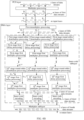
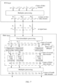
- FIG. 1A is a schematic diagram of an Ethernet communication architecture according to a related solution.
- data streams are obtained from a MAC module, and 64B/66B encoding processing, 256B/257B transcoding processing, alignment marker (alignment marker, AM) insertion processing, and RS encoding processing are sequentially performed on the data streams at the PCS layer.
- alignment marker alignment marker, AM
- RS encoding processing RS encoding processing
- CDR processing and bit multiplex processing are sequentially performed on the data streams received through the m input lanes, and data streams obtained through the processing are transmitted from the PMA layer to the PMD layer. Then, processing such as optical modulation is completed on the data streams at the PMD layer, and optical signals are output to a transmission medium, to complete an entire data operation at a transmitting end.
- a processing operation of data streams at a receiving end is a reverse operation. To be specific, processing at the PMD layer and processing at the PMA layer are sequentially completed at the receiving end. Then, the data streams are transmitted to the PCS layer through m output lanes.
- a delay needed for completing operations such as data alignment, deskewing, and reordering is 180 ns, which increases operation complexity and a delay.
- the existing Ethernet communication architecture is applicable only to a scenario with a throughput within 400 Gbps, and cannot satisfy a system error correction performance requirement required by next-generation Ethernet communication with a throughput greater than 400 Gbps.
- embodiments of this application provide an encoding method and a decoding method, applied to various optical communication scenarios such as medium- and short-distance interconnection communication, long-distance interconnection communication, cloud storage, cloud computing, a 5G base station backbone network, optical transmission, optical access, and base station fronthaul of a data center.
- the encoding method and the decoding method may be further applied to a next-generation Ethernet communication architecture with the throughput greater than 400 Gbps (for example, an 800 Gbps throughput or a 1600 Gbps throughput).
- the medium- and short-distance interconnection communication includes but is not limited to an optical transmission scenario in which a distance is less than or equal to 40 km.
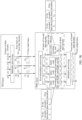
- FIG. 2 is a schematic diagram of an application scenario according to an embodiment of this application.
- any two hosts implement data communication by using optical modules.
- a data stream is transmitted from a host A to a host B.
- An optical module a is inserted into the host A
- an optical module b is inserted into the host B
- the host A may send the data stream to the host B via the optical module a and the optical module b sequentially.
- a data stream processing process of the optical module needs to be changed, to process m lanes of first data streams obtained through m input lanes, recover z lanes of original second data streams, and then separately perform inner-code encoding processing on each of the z lanes of second data streams to obtain z lanes of third data streams.
- Inner-code encoding processing is separately performed on each lane of second data stream, without performing complex processing such as deskewing and reordering on the z lanes of second data streams.
- each lane of second data stream can be separately transmitted, provided that each input lane and each output lane at the PMA layer each are enabled to uniquely correspond to one transmission medium.
- the system is adapted to the breakout mode well.
- the foregoing optical module may be understood as an optical module used when a data stream is transmitted to a receiving end, or may be understood as an optical module used when a data stream is received from a receiving end, for example, the foregoing optical module a and optical module b.
- a data stream may alternatively be transmitted from the host B to the host A.
- the host for example, the host A or the host B
- the host may further include but is not limited to a switching chip or an interface chip used in a router, a switch, or an optical transport network (optical transport network, OTN) transmission device, or may be a mobile phone chip, a CPU chip, an interface chip that needs high-speed communication, and the like. This is not limited herein.
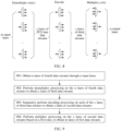
- FIG. 3 is a schematic flowchart of an encoding method according to an embodiment of this application. As shown in FIG. 3 , the encoding method may include the following steps.
- each of the z lanes of data streams corresponds to one physical coding sublayer lane (PCS lane) at the PCS layer, so that one lane of data stream can be transmitted through one physical coding sublayer lane.
- PCS lane physical coding sublayer lane
- multiplex processing may be performed, based on a first ratio, on the z lanes of data streams obtained through the RS encoding, to obtain the m lanes of first data streams (for example, D 1 , D 2 , ..., and D m ).
- first data streams for example, D 1 , D 2 , ..., and D m .
- the RS encoding herein may be understood as a first code in a concatenation code, namely, a code included in the PCS layer.
- the following operation may be further performed first: performing Q-stage processing on each of the z lanes of data streams obtained through the RS encoding, to obtain z lanes of ninth data streams, where each stage of processing in the Q-stage processing includes: performing round-robin distribution processing on a data stream obtained at a previous stage, to obtain at least two lanes of data substreams; performing delay processing on a third data substream to obtain a tenth data stream; and performing multiplex processing on a fourth data substream and the tenth data stream to obtain an output data stream obtained through current-stage processing, where the third data substream is at least one of the at least two lanes of data substreams, the fourth data substream is one lane of data substream that is in the at least two lanes of data substreams and on which delay processing is not
- the first ratio is a ratio of z to m, or may be understood as a ratio of a quantity of physical coding sublayer lanes to a quantity of the input lanes. For example, if the PCS layer intends to send 16 lanes of data streams to a PMA layer through four output lanes, multiplex processing needs to be performed on the 16 lanes of data streams based on the first ratio 16:4, to obtain four lanes of first data streams. It should be noted that an example in which the first ratio is 16:4 is merely used for description herein. During actual application, the first ratio may alternatively be another value, for example, 32:4, 32:16, or 16:8. This is not limited herein.
- the m lanes of first data streams include N RS codewords in total.
- a value of N may be 2, 4, 6, or the like. This is not limited herein.
- Each lane of first data stream may include (N ⁇ Codeword length of the RS codeword)/m bits.
- a data block length of the RS codeword may be 514 symbols
- a parity bit length is 62 symbols
- a total codeword length is 576 symbols
- a size of each symbol is 10 bits
- an error correction capability of the codeword is 31 error symbols correctable.
- a data block length of the RS codeword may be 514 symbols, a parity bit length is 30 symbols, a total codeword length is 544 symbols, a size of each symbol is 10 bits, and an error correction capability of the codeword is 15 error symbols correctable. It should be noted that the codeword length of the RS codeword is not limited in this application. During actual application, another codeword length may be further included, to implement error correction of different error symbols.
- the m lanes of first data streams are transmitted from the PCS layer to the PMA layer.
- the PMA layer may obtain the m lanes of first data streams through the m input lanes.
- the input lane may be understood as a physical medium attachment sublayer lane, a physical lane of an AUI interface, an output lane of an upper-layer PMA layer, or the like. This is not limited in this application.
- the m lanes of first data streams sent by the PCS layer may be processed to obtain the z lanes of second data streams (for example, F 1 , F 2 , ..., and F z ).
- a quantity of the z lanes of second data streams is equal to a quantity of the z lanes of data streams obtained by performing RS encoding on the to-be-transmitted data streams at the PCS layer in step 301.
- the z lanes of second data streams may also be referred to as PCS lane data streams in some possible examples.
- Each lane of second data stream may include Y to-be-encoded data blocks, and the to-be-encoded data block may be understood as a to-be-encoded information bit.
- a length of each to-be-encoded data block is k
- a parity bit length is p
- the length k of the to-be-encoded data block is 170 bits
- the total codeword length of the to-be-encoded data block is 180 bits after 10 parity bits are added.
- the length k of the to-be-encoded data block is 170 bits
- the total codeword length of the to-be-encoded data block is 179 bits after 9 parity bits are added.
- the total codeword length of the to-be-encoded data block is 181 bits after 11 parity bits are added.
- the length k of the to-be-encoded data block is 120 bits, the total codeword length of the to-be-encoded data block is 128 bits after 8 parity bits are added.
- different processing operations may be performed on the m lanes of first data streams to obtain the z lanes of second data streams.
- the z lanes of second data streams may be obtained by directly performing demultiplex processing on the m lanes of first data streams, may be obtained by further performing delay and multiplex processing on data streams obtained through demultiplex processing, or may be obtained by performing multiplex processing on data streams obtained through different RS encoding processing.
- the m lanes of first data streams may be processed in the following manner to obtain the z lanes of second data streams: performing demultiplex processing on the m lanes of first data streams based on a second ratio, to obtain the z lanes of second data streams, where the second ratio and the first ratio are reciprocal to each other.
- the second ratio is a ratio of m to z, and the second ratio and the first ratio are reciprocal to each other.
- the data streams namely, the z lanes of second data streams
- the quantity that is the same as the quantity of physical coding sublayer lanes can be obtained by directly performing demultiplexing based on the second ratio.
- the first ratio is 16:4
- the second ratio should be 4:16.
- 16 lanes of second data streams may be obtained through demultiplexing based on the second ratio 4:16.
- a bit length of each of the z lanes of second data streams is (N ⁇ Codeword length of the RS codeword)/z bits.
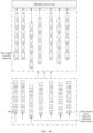
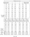
- FIG. 4A is a schematic diagram of data stream transmission according to an embodiment of this application. It can be learned from FIG. 4A that, at the PMA layer, after the m lanes of first data streams are obtained through the m input lanes, first demultiplex processing is performed on the m lanes of first data streams based on the second ratio (for example, m/z), to obtain the z lanes of second data streams. It should be noted that the first demultiplex processing may include but is not limited to DeMUX. Then, inner-code encoding processing is separately performed, by using an inner-code (Inner-FEC) sublayer, on each of the z lanes of second data streams obtained through the demultiplex processing. For details, refer to content described in subsequent step 303 for understanding. Details are not described herein. Then, multiplex processing is performed on z lanes of third data streams to obtain n lanes of fourth data streams. For details, refer to content described in subsequent step 304 for understanding. Details are not described herein.
- Inner-FEC Inner-
- demultiplex processing may alternatively be performed on the m lanes of first data streams at the PMA layer based on a second ratio in the following manner, to obtain the z lanes of second data streams: performing demultiplex processing on the m lanes of first data streams based on the second ratio, to obtain z lanes of fifth data streams; and then performing Q-stage processing on each of the z lanes of fifth data streams to obtain the z lanes of second data streams, where each stage of processing in the Q-stage processing includes: performing round-robin distribution processing on a data stream obtained at a previous stage, to obtain at least two lanes of data substreams; performing delay processing on a first data substream to obtain a sixth data stream; and performing multiplex processing on a second data substream and the sixth data stream to obtain an output data stream obtained through current-stage processing, where the first data substream is at least one of the at least two lanes of data substreams, the second data substream is one lane of data substream that is in the at least two lanes
- demultiplex processing is performed on the m lanes of first data streams based on the second ratio, to obtain the z lanes of fifth data streams (for example, G 1 , G 2 , ..., and G z ).
- the z lanes of fifth data streams for example, G 1 , G 2 , ..., and G z .
- One (for example, G 1 ) of the lanes of fifth data streams is used as an example.
- first-stage round-robin distribution processing needs to be performed on a data stream obtained for a previous time, to obtain at least two lanes of data substreams, and delay processing is performed on at least one of the lanes of data substreams to obtain a first-stage sixth data stream.
- the data stream obtained at the previous stage is obtained by sequentially performing round-robin distribution processing, delay processing, and multiplex processing on a previous-stage fifth data stream.
- a data stream that is obtained for a previous time and that is input for the first-stage round-robin distribution processing may be understood as the fifth data stream G 1 .
- a data stream that is obtained for a previous time and that is input for second-stage round-robin distribution processing may be understood as an output data stream obtained through first-stage first multiplex processing. Then, multiplex processing is performed on one lane of data substream (namely, the second data substream) that is in the at least two lanes of data substreams and on which delay processing is not performed and the first-stage sixth data stream to obtain an output data stream obtained through current-stage processing.
- one lane of corresponding second data stream may be obtained through Q th -stage processing. That is, the second data stream is the data stream obtained through the Q-stage processing.
- Q-stage processing may be understood as Q-stage concatenation processing, or may be understood as Q-stage iteration processing.
- the Q-stage concatenation processing may be understood with reference to content in subsequent FIG. 4B to FIG. 4D .
- the Q-stage iteration processing may be understood with reference to content in subsequent FIG. 4E .
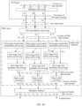
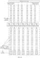
- FIG. 4B is another schematic diagram of data stream transmission according to an embodiment of this application. It can be learned from FIG. 4B that, based on the structure shown in FIG. 4A , at an inner-code sublayer, first demultiplex processing is first performed on the m lanes of first data streams to obtain the z lanes of fifth data streams. Then, the z lanes of fifth data streams are processed through Q-stage round-robin distribution processing, Q-stage first delay processing, and Q-stage first multiplex processing together, to obtain the z lanes of second data streams.
- the z lanes of fifth data streams may be transmitted to the first-stage round-robin distribution processing through z physical medium attachment sublayer lanes.
- the data stream that is obtained for the previous time and that is input for the first-stage round-robin distribution processing may be understood as the fifth data stream.
- a bit length of each stage of processing in the Q-stage concatenation processing is (N ⁇ Codeword length of the RS codeword)/z bits.
- G 1 One (for example, G 1 ) of the lanes of fifth data streams is used as an example.
- the fifth data stream G 1 is input for the first-stage round-robin distribution processing, and round-robin distribution processing is performed on the fifth data stream G 1 through the first-stage round-robin distribution processing, to obtain at least two lanes of first-stage data substreams (for example, G 11 1 , G 12 1 , G 13 1 , and G 14 1 ).
- G 11 1 and G 12 1 are used as an example.
- G 11 1 One (for example, G 11 1 ) of the lanes of first-stage data substreams is input for first-stage first delay processing, and delay processing is performed on the data substream G 11 1 through the first-stage first delay processing, to output one lane of first-stage sixth data stream (for example, J 1 1 ). Then, the first-stage sixth data stream J 1 1 and the other lane of first-stage data substream G 12 1 are input for the first-stage first multiplex processing, and multiplex processing is performed on the first-stage sixth data stream J 1 1 and the other lane of data substream G 12 1 through the first-stage first multiplex processing, to obtain one lane of first-stage output data stream (for example, P 1 1 ) obtained through the multiplex processing.
- G 11 1 may be understood as the foregoing first data substream
- G 12 1 may be understood as the foregoing second data substream.
- the first-stage output data stream P 1 1 is input for the second-stage round-robin distribution processing, and round-robin distribution processing is performed on the first-stage output data stream P 1 1 through the second-stage round-robin distribution processing, to obtain at least two lanes of second-stage data substreams (for example, G 11 2 , G 12 2 , G 13 2 , and G 14 2 ).
- G 11 2 and G 12 2 are used as an example.
- One (for example, G 11 2 ) of the lanes of data substreams is input for second-stage first delay processing, and delay processing is performed on the data substream G 11 2 through the second-stage first delay processing, to obtain one lane of second-stage sixth data stream (for example, J 1 2 ).
- the lane of second-stage sixth data stream J 1 2 and the other lane of second-stage data substream G 12 2 are input for second-stage second multiplex processing, and one lane of second-stage output data stream (for example, P 1 2 ) may be obtained through multiplex processing, to be specific, the second-stage second multiplex processing.
- the rest may be deduced by analogy, until Q th -stage round-robin distribution processing is performed on one lane of (Q-1) th -stage output data stream (for example, P 1 Q-1 ) to obtain at least two lanes of Q th -stage data substreams (for example, G 11 Q , G 12 Q , G 13 Q and G 14 Q ).
- Q th -stage round-robin distribution processing is performed on one lane of (Q-1) th -stage output data stream (for example, P 1 Q-1 ) to obtain at least two lanes of Q th -stage data substreams (for example, G 11 Q , G 12 Q , G 13 Q and G 14 Q ).
- G 11 Q and G 12 Q are used as an example.
- One (for example, G 11 Q ) of the lanes of Q th -stage data substreams is input for Q th -stage first delay processing, and delay processing is performed on the Q th -stage data substream G 11 Q through the Q th -stage first delay processing, to output one lane of Q th -stage sixth data stream (for example, J 1 Q ).
- the Q th -stage sixth data stream J 1 Q and the other lane of Q th -stage data substream G 12 Q are input for Q th -stage first multiplex processing, and multiplex processing is performed on the Q th -stage sixth data stream J 1 Q and the other lane of Q th -stage data substream G 12 Q through the Q th -stage first multiplex processing, to obtain one lane of data stream, namely, the second data stream (for example, F 1 ), finally input for encoding processing.
- the second data stream for example, F 1
- processing may also be performed through Q-stage first delay processing and Q-stage first multiplex processing that correspond to each of the other lanes of fifth data streams, to obtain corresponding second data streams.
- Q-stage first delay processing Q-stage first multiplex processing that correspond to each of the other lanes of fifth data streams, to obtain corresponding second data streams.
- inner-code encoding processing is separately performed on the z lanes of obtained second data streams to obtain z lanes of corresponding third data streams.
- inner-code encoding processing is separately performed on the z lanes of obtained second data streams to obtain z lanes of corresponding third data streams.
- multiplex processing is performed on the z lanes of third data streams to obtain n lanes of fourth data streams.
- content described in subsequent step 304 for understanding Details are not described herein.
- U bits may be used as a granularity, and round-robin distribution processing is performed, based on the granularity, on a data stream input for the stage of round-robin distribution processing.
- U w ⁇ N ⁇ (Bit length of one symbol in the RS codeword), where w is a positive integer greater than or equal to 1.
- each stage of first multiplex processing in the foregoing Q-stage first multiplex processing may include but is not limited to a symbol multiplex (symbol MUX) unit, a bit multiplex (bit MUX) unit, or the like.
- symbol MUX symbol multiplex
- bit MUX bit multiplex
- Each stage of first delay unit in the Q-stage first delay processing may alternatively be understood as a buffer (buffer) unit.
- FIG. 4C is another schematic diagram of data stream transmission according to an embodiment of this application.
- 16 lanes of fifth data streams (for example, G 1 , G 2 , ..., and G 16 ) are obtained.
- the fifth data stream G 16 is used as an example.
- the fifth data stream G 16 is input for the first-stage round-robin distribution processing, and round-robin distribution processing is performed on the fifth data stream G 16 through the first-stage round-robin distribution processing, to obtain at least two lanes of first-stage data substreams (for example, G 161 1 , G 162 1 , G 163 1 , and G 164 1 ).
- G 161 1 and G 162 1 are used as an example.
- One (for example, G 161 1 ) of the lanes of first-stage data substreams is input for the first-stage first delay processing, and delay processing is performed on the data substream G 161 1 through the first-stage first delay processing, to output one lane of first-stage sixth data stream (for example, J 16 1 ).
- the first-stage sixth data stream J 16 1 and the other lane of first-stage data substream G 162 1 are input for the first-stage first multiplex processing, and multiplex processing is performed on the first-stage sixth data stream J 161 1 and the other lane of data substream G 162 1 through the first-stage first multiplex processing, to obtain one lane of data stream, namely, a second data stream F 16 , finally input for the encoding processing and obtained through the multiplex processing.
- inner-code encoding processing is performed on the lane of second data stream F 16 obtained through the multiplex processing.
- a processing process of another fifth data stream such as G 1 , ..., or G 15 may also be understood with reference to the processing process of G 16 . Details are not described herein again.
- FIG. 4D is another schematic diagram of data stream transmission according to an embodiment of this application.
- 16 lanes of fifth data streams (for example, G 1 , G 2 , ..., and G 16 ) are obtained.
- the fifth data stream G 16 is used as an example.
- the fifth data stream G 16 is input for the first-stage round-robin distribution processing, and round-robin distribution processing is performed on the fifth data stream G 16 through the first-stage round-robin distribution processing, to obtain at least two lanes of first-stage data substreams (for example, G 161 1 , G 162 1 , G 163 1 , and G 164 1 ).
- G 161 1 and G 162 1 are used as an example.
- One (for example, G 161 1 ) of the lanes of first-stage data substreams is input for the first-stage first delay processing, and delay processing is performed on the data substream G 161 1 through the first-stage first delay processing, to output one lane of first-stage sixth data stream (for example, J 16 1 ).
- first-stage sixth data stream J 16 1 and the other lane of first-stage data substream G 162 1 are input for the first-stage first multiplex processing, and multiplex processing is performed on the first-stage sixth data stream J 16 1 and the other lane of data substream G 162 1 through the first-stage first multiplex processing, to obtain one lane of first-stage output data stream (for example, P 16 1 ) obtained through the multiplex processing.
- first-stage output data stream for example, P 16 1
- the first-stage output data stream P 16 1 is input for the second-stage round-robin distribution processing, and round-robin distribution processing is performed on the first-stage output data stream P 16 1 through the second-stage round-robin distribution processing, to obtain at least two lanes of second-stage data substreams (for example, G 161 2 , G 162 2 , G 163 2 , and G 164 2 ).
- G 161 2 and G 162 2 are used as an example.
- One (for example, G 161 2 ) of the lanes of data substreams is input for the first-stage first delay processing, and delay processing is performed on the data substream G 161 2 through the first-stage first delay processing, to obtain one lane of second-stage sixth data stream (for example, J 16 2 ).
- the lane of second-stage sixth data stream J 16 2 and the other lane of second-stage data substream G 162 2 are input for the second-stage second multiplex processing, and finally one lane of data stream, namely, a second data stream, for example, F 16 , finally input for encoding processing is output from the second-stage second multiplex processing.
- inner-code encoding processing is performed on the z lanes of second data streams obtained through the multiplex processing.
- a bit quantity of the foregoing sixth data stream is at least (N ⁇ Codeword length of the RS codeword)/(z ⁇ i) bits, where N is a positive integer, and i is a quantity of the data substreams.
- one-stage processing shown in FIG. 4C is used as an example.
- a bit length of the first-stage sixth data stream J 16 1 is at least (N ⁇ Codeword length of the RS codeword)/(z ⁇ 4) bits.
- FIG. 4E is another schematic diagram of data stream transmission according to an embodiment of this application. It can be learned from FIG. 4E that, based on the structure shown in FIG. 4A , at an inner-code sublayer, first demultiplex processing is first performed on the m lanes of first data streams to obtain the z lanes of fifth data streams. Then, Q-stage iteration processing is separately performed on the z lanes of fifth data streams to obtain the z lanes of second data streams.
- the z lanes of fifth data streams may be transmitted to the first-stage round-robin distribution processing through z physical medium attachment sublayer lanes.
- the data stream that is obtained for the previous time and that is input for the first-stage round-robin distribution processing may be understood as the fifth data stream.
- a bit length of each stage of processing in the Q-stage iteration processing is (N ⁇ Codeword length of the RS codeword)/z bits.
- One (for example, G 1 ) of the lanes of fifth data streams is used as an example.
- the fifth data stream G 1 is input for the first-stage round-robin distribution processing, and round-robin distribution processing is performed on the fifth data stream G 1 through the first-stage round-robin distribution processing, to obtain at least two lanes of first-stage data substreams (for example, G 11 1 and G 12 1 ).
- G 11 1 and G 12 1 are used as an example.
- One (for example, G 11 1 ) of the lanes of first-stage data substreams is input for first-stage first delay processing, and delay processing is performed on the data substream G 11 1 through the first-stage first delay processing, to output one lane of first-stage sixth data stream (for example, J 1 1 ).
- the first-stage sixth data stream J 1 1 and the other lane of first-stage data substream G 12 1 are input for the first-stage first multiplex processing, and multiplex processing is performed on the first-stage sixth data stream J 1 1 and the other lane of data substream G 12 1 through the first-stage first multiplex processing, to obtain one lane of first-stage output data stream (for example, P 1 1 ) obtained through the multiplex processing.
- G 11 1 may be understood as the foregoing first data substream
- G 12 1 may be understood as the foregoing second data substream.
- the first-stage output data stream P 1 1 continues to be input for the first-stage round-robin distribution processing, and round-robin distribution processing continues to be performed on the first-stage output data stream P 1 1 through the first-stage round-robin distribution processing, to obtain at least two lanes of second-stage data substreams (for example, G 11 2 and G 12 2 ).
- G 11 2 and G 12 2 are used as an example.
- One (for example, G 11 2 ) of the lanes of data substreams continues to be input for the first-stage first delay processing, and delay processing is performed on the data substream G 11 2 through the first-stage first delay processing, to obtain one lane of second-stage sixth data stream (for example, J 1 2 ).
- the lane of second-stage sixth data stream J 1 2 and the other lane of second-stage data substream G 12 2 continue to be input for first-stage second multiplex processing, and one lane of second-stage output data stream (for example, P 1 2 ) may be obtained through multiplex processing, to be specific, the first-stage second multiplex processing.
- Q th -stage round-robin distribution processing is performed on one lane of (Q-1) th -stage output data stream (for example, P 1 Q-1 ) to obtain at least two lanes of Q th -stage data substreams (for example, G 11 Q and G 12 Q ).
- G 11 Q and G 12 Q are used as an example.
- One (for example, G 11 Q ) of the lanes of Q th -stage data substreams continues to be input for the first-stage first delay processing, and delay processing is performed on the Q th -stage data substream G 11 Q through the first-stage first delay processing, to output one lane of Q th -stage sixth data stream (for example, J 1 Q ).
- the Q th -stage sixth data stream J 1 Q and the other lane of Q th -stage data substream G 12 Q are input for the first-stage first multiplex processing, and multiplex processing is performed on the Q th -stage sixth data stream J 1 Q and the other lane of Q th -stage data substream G 12 Q through the first-stage first multiplex processing, to obtain one lane of second data stream (for example, F 1 ).
- Q-stage iteration processing that corresponds to each of the other lanes of fifth data streams may also be performed to obtain corresponding second data streams.
- a specific processing process may be understood with reference to the foregoing processing process of the fifth data stream G 1 . Details are not described herein again.
- inner-code encoding processing is separately performed on the z lanes of obtained second data streams to obtain z lanes of corresponding third data streams.
- inner-code encoding processing is separately performed on the z lanes of obtained second data streams to obtain z lanes of corresponding third data streams.
- multiplex processing is performed on the z lanes of third data streams to obtain n lanes of fourth data streams.
- content described in subsequent step 304 for understanding Details are not described herein.
- bit length of the sixth data stream obtained through the Q-stage iteration processing may alternatively be understood with reference to the bit length of the sixth data stream obtained through the Q-stage concatenation processing. Details are not described herein again.
- the encoding method may further include: obtaining m lanes of seventh data streams through m first input lanes; and performing demultiplex processing on the m lanes of seventh data streams based on a second ratio, to obtain z lanes of eighth data streams; and the processing the m lanes of first data streams to obtain z lanes of second data streams includes: performing multiplex processing on z lanes of second data streams and the z lanes of eighth data streams to obtain the z lanes of second data streams obtained through the multiplex processing.
- the m lanes of seventh data streams are obtained by performing, at the first ratio, multiplex processing on the z lanes of data streams obtained through the RS encoding.
- the data streams obtained from the MAC module are divided into two parts of data streams with a same quantity. For each part, namely, z lanes of data streams, processing such as 64B/66B encoding processing, 256B/257B transcoding processing, alignment marker AM insertion processing, and RS encoding are sequentially completed on the z lanes of data streams at the PCS layer.
- multiplex processing is separately performed on the two parts based on the first ratio, to obtain the m lanes of first data streams and the m lanes of seventh data streams, where each part is z lanes of data streams obtained through the RS encoding processing.
- the PCS layer transmits the m lanes of first data streams to the PMA layer through the m output lanes, and transmits the m lanes of seventh data streams to the PMA layer through m first output lanes.
- the PMA layer after receiving, through the m input lanes, the m lanes of first data streams sent by the PCS layer, the PMA layer performs demultiplex processing on the m lanes of first data streams based on the second ratio, to obtain the z lanes of second data streams.
- the PMA layer After receiving the m lanes of seventh data streams through m first input lanes, the PMA layer also performs demultiplex processing on the m lanes of seventh data streams based on the second ratio, to obtain B lanes of eighth data streams. For details, refer to FIG. 4A for understanding. Details are not described herein again. Then, the PMA layer may perform multiplex processing on the z lanes of second data streams and the z lanes of eighth data streams to obtain the z lanes of second data streams obtained through the multiplex processing.
- the 16 lanes of second data streams are represented as F 1 , F 2 , ..., and F 16
- the 16 lanes of eighth data streams are represented as W 1 , W 2 , ..., and W 16
- Second multiplex processing may be performed on the second data stream F 1 and the eighth data stream W 1 to obtain one lane of second data stream obtained through the processing.
- second multiplex processing may also be performed on the second data stream F 2 and the eighth data stream W 2 to obtain another lane of second data stream obtained through the processing.
- 16 lanes of second data streams obtained through the multiplex processing may be obtained.
- inner-code encoding processing is performed on the z lanes of second data streams obtained through the multiplex processing.
- the encoding method may further include: separately performing Q-stage processing on each of the z lanes of second data streams obtained through the multiplex processing, to obtain z lanes of twelfth data streams, where each stage of processing in the Q-stage processing includes: performing round-robin distribution processing on a data stream obtained at a previous stage, to obtain at least two lanes of data substreams; performing delay processing on a fifth data substream to obtain a thirteenth data stream; and performing multiplex processing on a sixth data substream and the thirteenth data stream to obtain an output data stream obtained through current-stage processing, where the fifth data substream is at least one of the at least two lanes of data substreams, the sixth data substream is one lane of data substream that is in the at least two lanes of data substreams and on which delay processing is not performed, Q is a
- Q-stage processing is separately performed on each of the z lanes of second data streams obtained through the multiplex processing.
- a specific process of the Q-stage processing may be understood with reference to the content described in (2). Details are not described herein again.
- encoding processing is separately performed on each of the z lanes of twelfth data streams. For details, refer to content described in subsequent step 303 for understanding. Details are not described herein.
- a bit length of the thirteenth data stream is at least (N ⁇ Codeword length of the RS codeword)/(z ⁇ i) bits, where N is a positive integer, and i is a quantity of the data substreams.
- N is a positive integer
- i is a quantity of the data substreams.
- the z lanes of obtained second data streams may be understood as data streams on which processing such as data alignment, deskewing, or reordering is not performed.
- the m lanes of first data streams may be processed in another manner in addition to any manner in (1) to (3) above, to obtain the z lanes of second data streams. This is not limited herein.
- C inner-code sublayers are instantiated at the PMA layer based on an integer multiple of the quantity of physical coding sublayer lanes. That is, C is an integer multiple of B.
- C is an integer multiple of B.
- each lane of data stream obtained through the encoding processing includes an FEC codeword.
- the inner-code sublayer in this application may also be referred to as an inner-forward error correction (inner-forward error correction, Inner-FEC) coding sublayer.
- inner-FEC inner-forward error correction
- the inner-code encoding processing may be understood as a second code in the concatenation code, and the concatenation code consists of the inner-code encoding processing and the RS encoding described in step 301.
- 16 inner-code encoding processing operations namely, H 1 , H 2 , ..., and H 16 , are separately performed at the inner-code sublayer of the PMA layer. Then, inner-code encoding processing is performed on the data stream F 1 through the inner-code encoding processing operation H 1 , inner-code encoding processing is performed on the data stream F 2 through the inner-code encoding processing operation H 2 , ..., and inner-code encoding processing is performed on the data stream F 16 through the inner-code encoding processing operation H 16 .
- 32 inner-code encoding processing operations may alternatively be separately performed at the inner-code sublayer.
- inner-code encoding processing is performed on the data stream F 1 through the two inner-code encoding processing operations H 1 and H 2
- inner-code encoding processing is performed on the data stream F 2 through the two inner-code encoding processing operations H 3 and H 4
- inner-code encoding processing is performed on the data stream F 16 through the two inner-code encoding processing operations H 31 and H 32 .
- 16 inner-code encoding processing operations and the 32 inner-code encoding processing operations are merely used as examples for description herein.
- 64 inner-code encoding processing operations may alternatively be performed at the inner-code sublayer, and inner-code encoding processing is performed on each lane of second data stream through four different inner-code encoding processing operations.
- 128 inner-code encoding processing operations or the like may be performed provided that C is an integer multiple of z. This is not limited herein.
- inner-code encoding processing is performed on the data stream F 1 through the inner-code encoding processing operation H 1
- inner-code encoding processing is performed on the data stream F 2 through the inner-code encoding processing operation H 2
- inner-code encoding processing is performed on the data stream F 16 through the inner-code encoding processing operation H 16 , ...
- inner-code encoding processing is performed on the data stream F 32 through the inner-code encoding processing operation H 32 .
- 64 inner-code encoding processing operations namely, H 1 , H 2 , H 3 , H 4 , ..., H 63 , and H 64 , may alternatively be performed at the inner-code sublayer.
- inner-code encoding processing is performed on the data stream F 1 through the two inner-code sublayers H 1 and H 2
- inner-code encoding processing is performed on the data stream F 2 through the two inner-code encoding processing operations H 3 and H 4
- inner-code encoding processing is performed on the data stream F 32 through the two inner-code encoding processing operations H 63 and H 64 .
- the 32 inner-code encoding processing operations and the 64 inner-code encoding processing operations that are performed at the inner-code sublayer are merely used as examples for description herein.
- 128 inner-code encoding processing operations may alternatively be performed, and inner-code encoding processing is performed on each lane of second data stream through four different inner-code encoding processing operations; and so on. This is not limited herein.
- z may alternatively be another value, and a value of z depends on a requirement. This is not limited herein.
- inner-code encoding may be performed in different manners in different scenarios to enable a decoding sublayer to directly determine a boundary position of each codeword in a subsequent decoding process to improve decoding accuracy.
- inner-code encoding may be performed in different manners in different scenarios to enable a decoding sublayer to directly determine a boundary position of each codeword in a subsequent decoding process to improve decoding accuracy.
- the first data block is the at least C/z consecutive to-be-encoded data blocks in the corresponding second data stream, or may be understood as consisting of the at least C/z consecutive to-be-encoded data blocks.
- a length of the first data block is a sum of lengths of the at least C/z consecutive to-be-encoded data blocks.
- each lane of second data stream includes the Y to-be-encoded data blocks in total that are I 1 , I 2 , ..., and I Y .
- lengths of the to-be-encoded data blocks I 1 , I 2 , ..., and I Y are k
- the length of the first data block is correspondingly k
- the length of the first data block is correspondingly 2k. It should be noted that the foregoing merely uses an example in which the lengths of I 1 , I 2 , ..., and I Y are all k for description. During actual application, lengths of all to-be-encoded data blocks may alternatively be different. This is not limited herein.
- a quantity of the obtained FEC codewords is related to a quantity of the to-be-encoded data blocks that the first data block consists of.
- the lane of second data stream F 1 includes Y to-be-encoded data blocks in total that are I 1 , I 2 , ..., and I Y .
- the 16 inner-code encoding processing operations namely, H 1 , H 2 , ..., and H 16
- the first data block may be understood as one of the Y to-be-encoded data blocks I 1 , I 2 , ..., and I Y .
- inner-code encoding processing may be performed on the to-be-encoded data block I 1 (for example, k bits) in the second data stream F 1 by performing the inner-code encoding processing operation H 1 , and one FEC codeword (for example, an FEC codeword 1) may be obtained in this case; inner-code encoding processing may be performed on a to-be-encoded data block I 2 in the second data stream F 2 by performing the inner-code encoding processing operation H 2 , and one FEC codeword may be obtained in this case; ...; and by analogy, inner-code encoding processing may be performed on a to-be-encoded data block I 16 in the second data stream F 16 by performing the inner-code encoding processing operation H 16 , and one FEC codeword may be obtained in this case.
- FEC codeword for example, an FEC codeword 1
- inner-code encoding processing may be performed on a to-be-encoded data block I 2 in the second data stream F 2 by performing the inner
- inner-code encoding processing is performed on the to-be-encoded data block I 1 by performing the inner-code encoding processing operation H 1 is merely used for description.
- inner-code encoding processing may alternatively be performed on the to-be-encoded data block I 2 or I 3 by performing the inner-code encoding processing operation H 1 .
- the other inner-code encoding processing operations may also be understood with reference to the inner-code encoding processing operation H 1 . Details are not described herein again.
- the other second data streams F 2 , ..., and F 16 may also be actually understood with reference to the second data stream F 1 . Details are not described herein again.
- the first data block may be understood as at least two consecutive to-be-encoded data blocks in the Y to-be-encoded data blocks I 1 , I 2 , ..., and Iy.
- the first data block may consist of I 1 and I 2 , or may consist of I 3 and I 4 . This is not limited herein.
- FIG. 5B is another schematic diagram of performing an inner-code encoding processing operation according to an embodiment of this application. It can be learned from FIG.
- inner-code encoding processing may be performed, by performing the inner-code encoding processing operations H 1 and H 2 , on a first data block (for example, k+k bits) consisting of I 1 and I 2 in the second data stream F 1 , and two FEC codewords (for example, an FEC codeword 1 and an FEC codeword 2) may be obtained in this case; inner-code encoding processing may be performed, by performing the inner-code encoding processing operations H 3 and H 4 , on a first data block consisting of I 3 and I 4 in the second data stream F 2 , and two FEC codewords may be obtained in this case; ...; and by analogy, inner-code encoding processing may be performed, by performing the inner-code encoding processing operations H 31 and H 32 , on a first data block consisting of I 31 and I 32 in the second data stream F 16 , and two FEC codewords may be obtained in this case.
- inner-code encoding processing by performing the inner-code encoding processing operation H 1 and H 2 , on the first data block consisting of I 1 and I 2 is merely used for description.
- inner-code encoding processing may alternatively be performed, by performing the inner-code encoding processing operations H 1 and H 2 , on a first data block consisting of I 3 and I 4 in the second data stream F 1 or a first data block consisting of I 31 and I 32 in the second data stream F1.
- the other inner-code encoding processing operations may also be understood with reference to the inner-code encoding processing operation H 1 and H 2 . Details are not described herein again.
- the other second data streams F 2 , ..., and F 16 may also be actually understood with reference to the second data stream F 1 . Details are not described herein again.
- the 64 inner-code encoding processing operations may alternatively be performed at the inner-code sublayer.
- the first data block may be understood as four consecutive to-be-encoded data blocks in the Y to-be-encoded data blocks I 1 , I 2 , ..., and I Y .
- the first data block may consist of I 1 , I 2 , I 3 , and I 4 , or may consist of I 5 , I 6 , I 7 , and I 8 . This is not limited herein.
- inner-code encoding processing may be performed, by performing the inner-code encoding processing operations H 1 to H 4 , on a first data block (for example, k+k+k+k bits) consisting of I 1 , I 2 , I 3 , and I 4 in the second data stream F 1 , and four FEC codewords may be obtained in this case; inner-code encoding processing may be performed, by performing the inner-code encoding processing operations H 5 to H 8 , on a first data block consisting of I 5 , I 6 , I 7 , and I 8 in the second data stream F 2 , and four FEC codewords may be obtained in this case; ...; and by analogy, inner-code encoding processing may be performed, by performing the inner-code encoding processing operations H 61 to H 64 , on a first data block consisting of I 61 , I 62 , I 63 , and 1 64 in the second data stream F 16 , and four FEC codewords may be obtained in this case;
- inner-code encoding processing by performing the inner-code encoding processing operations H 1 to H 4 , on the first data block consisting of I 1 , I 2 , I 3 , and I 4 in the second data stream F 1 is merely used for description.
- inner-code encoding processing may alternatively be performed, by performing the inner-code encoding processing operations H 1 to H 4 , on a first data block consisting of I 5 , I 6 , I 7 , and I 8 or a first data block consisting of I 61 , I 62 , I 63 , and I 64 in the second data stream F 1 . This is not limited herein.
- the other inner-code encoding processing operations may also be understood with reference to the inner-code encoding processing operation H 1 and H 4 . Details are not described herein again.
- the other second data streams F 2 , ..., and F 16 may also be actually understood with reference to the second data stream F 1 . Details are not described herein again.
- the first identifier may be further inserted at the position of the codeword boundary of any one of the FEC codewords.
- the first identifier may be inserted at a position of a codeword boundary of the FEC codeword (for example, the FEC codeword 1) obtained by performing the inner-code encoding processing operation H 1 .
- the first identifier may be inserted at a position of a codeword boundary of any one of the two FEC codewords (for example, the FEC codeword 1 and the FEC codeword 2) obtained by performing the inner-code encoding processing operation H 1 and H 2 .
- the first identifier is inserted at a position of a codeword boundary of the FEC codeword 1, or the first identifier is inserted at a position of a codeword boundary of the FEC codeword 2.
- inserting the first identifier at the position of the codeword boundary of any one of the FEC codewords may alternatively be understood as inserting one first identifier at an interval of C/z FEC codewords.
- the throughput or the baud rate of the FEC codeword obtained through the insertion of the first identifier is the integer multiple of the reference clock.
- the throughput of the FEC codeword obtained through the insertion of the first identifier may be 910 Gbps.
- a data transmission rate is represented by a baud rate
- a baud rate of each physical coding sublayer lane at the PCS layer is 26.5625 Gbaud.
- a total length of the entire FEC codeword obtained through the insertion of the first identifier may change to 182 bits.
- the baud rate of the corresponding physical coding sublayer lane changes to 28.4375 Gbaud.
- the throughput of the FEC codeword obtained through the insertion of the first identifier may be 900 Gbps.
- a data transmission rate is represented by a baud rate
- a baud rate of each physical coding sublayer lane at the PCS layer is 26.5625 Gbaud.
- a total length of the obtained FEC codeword is 179 bits.
- a total length of the entire FEC codeword obtained through the insertion of the first identifier may change to 180 bits.
- the baud rate of the corresponding physical coding sublayer lane changes to 28.125 Gbaud.
- the throughput is 850 Gbps and an example in which the baud rate is 26.5625 Gbaud are merely used for description.
- a transmission rate of the data stream at the PCS layer should be related to load of the RS codeword.
- examples in which the throughputs of the FEC codeword obtained through the insertion of the first identifier are 910 Gbps and 900 Gbps are merely used for description, and examples in which the baud rate of the physical coding sublayer lane changes to 26.5625 Gbaud and 28.125 Gbaud are merely used for description.
- the reference clock may be understood as 156.25 megahertz (MHz), or may be another value during actual application. This is not limited herein.
- the foregoing reference clock indicates a data stream transmission frequency, namely, a quantity of times of transmission that may be performed per second.
- Both the baud rate and the throughput may represent a data stream transmission rate.
- the throughput represents a quantity of bits transmitted per second, and the baud rate represents a quantity of symbols transmitted per second. For example, five symbols may be transmitted each time, and 10 times of transmission may be performed per second. In this case, a total of 50 symbols may be transmitted per second.
- the position of the codeword boundary may be understood as a codeword start and/or a codeword end. This is not limited herein.
- the codeword boundary of the FEC codeword is identified by the first identifier, so that a boundary position of each FEC codeword can be determined by directly identifying the first identifier in a subsequent decoding process, and a case in which inner-code decoding is ineffective in a case of delay skew and an unknown data start position is avoided.
- first identifier may be a preset identifier sequence, or may be obtained based on a bit value of the first data block. Descriptions are separately provided by using an example below.
- the first identifier is the preset identifier sequence.
- the first identifier may be a sequence consisting of "1" and "0", or may be another known sequence. This is not limited herein.
- FIG. 6A is a schematic diagram of inserting a first identifier according to an embodiment of this application. As shown in FIG. 6A , the first identifier, namely, a sequence consisting of "1" and "0", is added at a position of a codeword start of an FEC codeword, and the first identifier occupies two bits. Therefore, after the first identifier is added at a position of a codeword boundary of the FEC codeword, a total length of the codeword changes from n bits to n+2 bits.
- the length of the first data block is 170 bits
- the total length of the FEC codeword is 180 bits after inner-code encoding processing is performed.
- the length of the entire FEC codeword obtained through the insertion of the first identifier changes to 182 bits.
- the first identifier is the preset identifier sequence
- a sequence such as "101010” or “1010” may alternatively be selected as the first identifier. This is not limited herein.
- the first identifier is obtained based on the bit value of the first data block.
- first identifiers may alternatively be obtained for different bit values in the first data block.
- Manner 1 The first identifier is obtained based on a value of a first bit in the first data block. It should be noted that the first bit is any one of at least one bit in the first data block.
- FIG. 6B is a schematic diagram of a value assignment manner of a first identifier according to an embodiment of this application.
- the first bit may be the 0 th bit in the first data block. If a value of the 0 th bit is "0", the first identifier, that is, "1”, may be obtained by directly performing a negation operation on the value of the 0 th bit. Alternatively, if a value of the 0 th bit is "1", the first identifier, that is, "0”, may be obtained by directly performing a negation operation on the value of the 0 th bit. This is not specifically limited herein.
- FIG. 6B is a schematic diagram of a value assignment manner of a first identifier according to an embodiment of this application. It can be learned from FIG. 6B that the first bit may be the 0 th bit in the first data block. If a value of the 0 th bit is "0", the first identifier, that is, "1”, may be obtained by directly performing a neg
- the first bit may alternatively be the 1 st bit, the 2 nd bit, or the like in the first data block.
- the length of the first data block is 180 bits.
- a last bit may be selected for negation. That is, a value of the 179 th bit is selected to directly perform a negation operation, to obtain the first identifier.
- the first identifier is obtained by performing a negation operation on a bit at a start position or an end position of the first data block. This helps the PMA layer at a receiving end quickly determine a codeword boundary.
- the first identifier is obtained based on bit values of at least L second bits in the first data block, where there is an interval of s bits between every two adjacent second bits in the L second bits, L ⁇ 2, s ⁇ 0, and L and s are integers.
- one second bit is selected at an interval of s bits, and a total of L second bits are selected.
- the L second bits may be processed through an exclusive OR operation, an OR operation, or an AND operation, to obtain the first identifier.
- L is 4 and s is 2
- L may alternatively be 8, and s is 3; L is 6, and s is 4; or the like.
- neither a value of L nor a value of s is limited.
- the first identifier may be determined in another manner in addition to 1 and 2 above. This is not specifically limited in this application.
- the second data block may be understood as consisting of the first data block and the first identifier, and a length of the second data block is a sum of a length of the first data block and a quantity of bits occupied by the first identifier.
- the first identifier is inserted into each to-be-encoded data block in the first data block. For example, when the first data block shown in FIG.
- the first identifier may be inserted at a position of a codeword boundary of the to-be-encoded data block I 1 , and the first identifier may be inserted at a position of a codeword boundary of the to-be-encoded data block I 2 . If the length of the first data block is k (that is, the first data block occupies k bits), and the first identifier occupies one bit, the length of the second data block is k+2 bits.
- Inner-code encoding processing may be performed on a second data block in each lane of second data stream.
- first data block may be understood with reference to content in (1).
- first identifier may alternatively be understood with reference to the content described in 1 and 2. Details are not described herein again.
- the encoding method may further include: identifying an alignment marker in the lane of second data stream, where the alignment marker identifies a symbol boundary in the corresponding second data stream; and determining the symbol boundary in the corresponding second data stream based on the alignment marker.
- a common alignment marker of an AM alignment block is added to each of the m lanes of first data streams.
- each lane of second data stream includes the corresponding alignment marker, and the symbol boundary in the lane of second data stream is identified by the alignment marker. Therefore, at the PMA layer, after the m lanes of first data streams are processed in any one of the possible manners in FIG. 4A to FIG. 4F to obtain the z lanes of second data streams, the alignment marker included in each lane of second data stream may be further identified. After the corresponding alignment marker is identified, the alignment marker is locked, so that the symbol boundary in the corresponding second data stream may be determined.
- an AM alignment block of a 120-bit known sequence is added to each lane of first data stream, and there is a 48-bit common alignment marker in the AM alignment block of the 120-bit known sequence.
- locking and alignment may be implemented provided that the 48-bit common alignment marker is identified in an operation at a symbol boundary of the RS codeword.
- inner-code encoding processing is separately performed on the z lanes of second data streams.
- inner-code encoding processing is separately performed on the z lanes of second data streams.
- FIG. 7 is another schematic diagram of data stream transmission according to an embodiment of this application.
- alignment processing may be separately performed on the z lanes of second data streams, and then inner-code encoding processing is separately performed.
- 304 Perform multiplex processing on the z lanes of third data streams to obtain the n lanes of fourth data streams, where n is a positive integer.
- the PMAlayer still needs to perform multiplex processing on the z lanes of third data streams to obtain the n lanes of fourth data streams, and then transmits the n lanes of fourth data streams to a PMA layer at the receiving end through the n output lanes.
- the PMA layer multiplexes the z lanes of third data streams based on a third ratio (that is, z/n), to obtain the n lanes of fourth data streams.
- the PMA layer may first multiplex the z lanes of third data streams based on a fourth ratio (that is, z/m), to obtain m lanes of data streams, and then perform multiplex processing on the m lanes of data streams based on a fifth ratio (that is, m/n), to obtain the n lanes of fourth data streams.
- a specific manner is not limited in this application. It should be noted that a value of n may be 4, 8, 16, or the like. This is not limited herein.
- FIG. 8 is a schematic diagram of overall transmission of data streams at a PMA layer.
- m lanes of first data streams are obtained through the m input lanes, and first demultiplex processing is performed on the m lanes of first data streams based on a ratio of m/z, to obtain z lanes of PCS lane data streams, namely, the z lanes of second data streams.
- C inner-code encoding processing operations at the inner-code sublayer are performed to separately perform encoding processing on the z lanes of PCS lane data streams to obtain the z lanes of third data streams, where the inner-code encoding processing of each lane of PCS lane data stream is implemented through C/z inner-code encoding processing operations.
- multiplex processing is performed on the z lanes of third data streams based on z/n, to obtain the n lanes of fourth data streams, and the n lanes of fourth data streams are transmitted through the n output lanes.
- FIG. 3 to FIG. 8 mainly describe the encoding method provided in embodiments of this application.
- the following describes a decoding method provided in embodiments of this application.
- FIG. 9 is a schematic flowchart of a decoding method according to an embodiment of this application. As shown in FIG. 9 , the decoding method may include the following steps.
- a PMA layer at a transmitting end may send the n lanes of fourth data streams to a PMD layer.
- signals may be transmitted to a PMD layer at a receiving end by using a transmission medium or the like.
- the PMD layer performs conversion processing on the signals received from the transmission medium, to obtain the n lanes of fourth data streams.
- the PMD layer may transmit the n lanes of fourth data streams to a PMA layer on a receiving end side through n output lanes. In this way, the PMA layer may obtain the n lanes of fourth data streams through the n input lanes.
- demultiplex processing may be performed on the n lanes of fourth data streams based on a reciprocal of a third ratio, to obtain the z lanes of third data streams.
- the third ratio may be understood with reference to step 304 in FIG. 3 . Details are not described herein again.
- a decoding processing procedure is an inverse process of the encoding processing in FIG. 3 .
- C inner-code decoding processing operations may also be performed at an inner-code sublayer, so as to separately perform inner-code decoding processing on one lane of third data stream by performing C/z different inner-code decoding processing operations.
- the decoding method may further include: identifying, based on a first identifier and/or a decoding flag bit, a codeword boundary of FEC codeword obtained through encoding, where the decoding flag bit indicates whether the inner-code decoding processing is successful.
- the z lanes of third data streams each include a corresponding first identifier.
- a position of a codeword boundary of an FEC codeword in each lane of third data stream may be learned of by identifying the first identifier and/or a decoding flag bit, so that decoding efficiency and decoding accuracy are further improved.
- the PMA layer may further determine, by using the decoding flag bit, whether inner-code decoding processing is successful; and when the decoding flag bit indicates that the inner-code decoding processing is successful, the PMA layer identifies the codeword boundary of the FEC codeword based on the first identifier, thereby performing decoding processing on the FEC codeword obtained through encoding.
- the identifying, based on a first identifier and/or a decoding flag bit, a codeword boundary of FEC codeword obtained through encoding may be understood as three cases. To be specific, 1 the codeword boundary of the FEC codeword obtained through the encoding may be identified based on the first identifier; 2 the codeword boundary of the FEC codeword obtained through the encoding may be identified based on the decoding flag bit; and (3) the codeword boundary of the FEC codeword obtained through the encoding may be identified based on the first identifier and the decoding flag bit.
- a specific manner is not limited in this application.
- the foregoing decoding flag bit may be fed back in a decoding processing process, or may not be fed back. This is not limited herein.
- the PMA layer after obtaining the z lanes of second data streams, the PMA layer performs multiplex processing on the z lanes of second data streams based on the first ratio, to obtain the m lanes of first data streams.
- the first ratio may be 16:4, and four lanes of first data streams are obtained through the multiplex processing.
- FIG. 10A is a schematic diagram of transmission of data streams in a decoding process according to an embodiment of this application. It can be learned from FIG. 10A that demultiplex processing is first performed on n lanes of fourth data streams to obtain z lanes of third data streams. Then, inner-code decoding processing is separately performed on the z lanes of third data streams at an inner-code sublayer to obtain z lanes of second data streams. Finally, the z lanes of second data streams are processed.
- an electrical signal is obtained through optical-electrical conversion at a PMD layer, a data and clock recovery operation first needs to be performed on the electrical signal by a CDR unit. Shorter time needed by the CDR unit to recover a clock and data is more favorable to a system.
- the decoding method may further include: generating a first signal based on the first identifier and/or the decoding flag bit before identifying the codeword boundary of the FEC codeword based on the first identifier and/or the decoding flag bit, where the first signal is for determining data and clock information.
- FIG. 10B is another schematic diagram of transmission of data streams in a decoding process according to an embodiment of this application. It can be learned from FIG. 10B that, based on FIG. 10A , before z lanes of third data streams are obtained through demultiplex processing, clock and data recovery processing is first performed on n lanes of fourth data streams. Then, demultiplex processing is performed on n lanes of fourth data streams obtained through the clock and data recovery processing, to obtain the z lanes of third data streams, and then inner-code decoding processing is separately performed on the z lanes of third data streams. It should be noted that a CDR unit uniquely corresponds to a data stream transmitted in an input lane.
- the inner-code sublayer may first detect a first identifier and/or a decoding flag bit, to generate a feedback signal, namely, a first signal.
- a process of recovering the data and the clock by the CDR unit may be accelerated, data and clock information is determined in advance, and time needed for system locking is reduced.
- a codeword boundary of each lane of third data stream can be determined provided that a boundary identifier in the lane of the third data stream is identified, so as to separately perform inner-code decoding processing on each of the z lanes of third data streams, without performing operations such as deskewing and reordering on the data streams, which reduces operation complexity and a delay.
- the PMA layer includes a corresponding hardware structure and/or software module for executing each function.
- the PMA layer can be implemented by hardware or a combination of hardware and computer software. Whether a function is performed by hardware or hardware driven by computer software depends on particular applications and design constraints of the technical solutions. Persons skilled in the art may use different methods to implement the functions for each particular application, but it should not be considered that the implementation goes beyond the scope of this application.
- the PMA layer may be implemented by one physical device, for example, an optical module, or another encoding apparatus or decoding apparatus, may be jointly implemented by a plurality of physical devices, or may be a logical functional unit in one physical device. This is not specifically limited in embodiments of this application.
- the PMA layer may be implemented by a communication device in FIG. 11.
- FIG. 11 is a schematic diagram of a hardware structure of a communication device according to an embodiment of this application.
- the communication device includes at least one processor 1101, a memory 1102, and a transceiver 1103.
- the processor 1101 may be a general-purpose central processing unit CPU, a microprocessor, an application-specific integrated circuit (application-specific integrated circuit), or one or more integrated circuits configured to control program execution of the solutions in this application.
- the processor 1101 can perform operations, for example, determining, analysis, and operation, including: processing m lanes of first data streams to obtain z lanes of second data streams; separately performing inner-code encoding processing on each of the z second data streams to obtain z lanes of third data streams; and the like.
- the transceiver 1103 is any apparatus such as a transceiver, and is configured to communicate with another device or a communication network such as the Ethernet, a radio access network (radio access network, RAN), or a wireless local area network (wireless local area network, WLAN).
- the transceiver 1103 may be connected to the processor 1101.
- the transceiver 1103 may obtain the m lanes of first data streams and the like.
- the memory 1102 may be a read-only memory (read-only memory, ROM) or another type of static storage device that can store static information and instructions, or a random access memory (random access memory, RAM) or another type of dynamic storage device that can store information and instructions, or may be an electrically erasable programmable read-only memory (electrically erasable programmable read-only memory, EEPROM), a compact disc read-only memory (compact disc read-only memory, CD-ROM) or another compact disc storage, an optical disc storage (including a compressed optical disc, a laser disc, an optical disc, a digital versatile disc, a Blu-ray disc, or the like), a magnetic disk storage medium or another magnetic storage device, or any other medium that can be for carrying or storing expected program code in a form of instructions or a data structure and that can be accessed by a computer, but is not limited thereto.
- the memory 1102 may exist independently, or may be connected to the processor 1101.
- the memory 1102 may alternatively be integrated with the processor
- the memory 1102 is configured to store computer-executable instructions for performing the solutions in this application, and execution is controlled by the processor 1101.
- the processor 1101 is configured to execute the computer-executable instructions stored in the memory 1102, to implement the encoding method and the decoding method provided in the foregoing method embodiments of this application.
- the computer-executable instructions in this embodiment of this application may also be referred to as application program code. This is not specifically limited in this embodiment of this application.
- the processor 1101 may include one or more CPUs such as a CPU 0 and a CPU 1 in FIG. 11 .
- the PMA layer may be divided into functional units based on the foregoing method embodiments.
- each functional unit may be obtained through division based on each corresponding function, or two or more functions may be integrated into one functional unit.
- the integrated functional unit may be implemented in a form of hardware, or may be implemented in a form of a software functional unit.
- FIG. 12 is a schematic diagram of a structure of an encoding apparatus according to an embodiment of this application.
- an embodiment of the encoding apparatus in this application may include a first obtaining unit 1201 and a first processing unit 1202.
- the first obtaining unit 1201 is configured to obtain m lanes of first data streams through m input lanes, where m is a positive integer. For details, refer to content of step 301 in FIG. 3 for understanding. Details are not described herein again.
- the first processing unit 1202 is configured to: process the m lanes of first data streams to obtain z lanes of second data streams; separately perform encoding processing on each of the z lanes of second data streams to obtain z lanes of third data streams; and perform multiplex processing on the z lanes of third data streams to obtain n lanes of fourth data streams, where n and z are both positive integers.
- process the m lanes of first data streams to obtain z lanes of second data streams
- multiplex processing on the z lanes of third data streams to obtain n lanes of fourth data streams, where n and z are both positive integers.
- each of the z lanes of second data streams includes a to-be-encoded data block
- the first processing unit 1202 is configured to: perform encoding processing on a first data block to obtain one or more FEC codewords, where the first data block is at least C/z consecutive to-be-encoded data blocks in the corresponding second data stream, C is a positive integer, and C is an integer multiple of z; and insert a first identifier at a position of a codeword boundary of any one of the FEC codewords, where the first identifier identifies the codeword boundary of the FEC codeword, and a throughput or a baud rate of an FEC codeword obtained through insertion of the first identifier is an integer multiple of a reference clock.
- the first processing unit 1202 is configured to: perform encoding processing on a first data block to obtain one or more FEC codewords, where the first data block is at least C/z consecutive to-be-encoded data blocks in the corresponding second data stream, C
- each of the z lanes of second data streams includes a to-be-encoded data block
- the first processing unit 1202 is configured to: insert a first identifier into each to-be-encoded data block in a first data block to obtain a second data block, where the first data block is C/z consecutive to-be-encoded data blocks, C is a positive integer, and C is an integer multiple of z; and perform encoding processing on the second data block to obtain an FEC codeword, where a throughput or a baud rate of the FEC codeword is an integer multiple of a reference clock.
- the first processing unit 1202 is configured to: insert a first identifier into each to-be-encoded data block in a first data block to obtain a second data block, where the first data block is C/z consecutive to-be-encoded data blocks, C is a positive integer, and C is an integer multiple of z; and perform encoding processing on the second data block to obtain an FEC codeword, where a
- the first identifier is a preset identifier sequence.
- the first identifier is a preset identifier sequence.
- the first identifier is obtained based on a value of a first bit in the first data block, where the first bit is any one of at least one bit in the first data block; or the first identifier is obtained based on bit values of at least L second bits in the first data block, where there is an interval of s bits between every two adjacent second bits in the L second bits, L ⁇ 2, s ⁇ 0, and L and s are integers.
- bit values of at least L second bits in the first data block where there is an interval of s bits between every two adjacent second bits in the L second bits, L ⁇ 2, s ⁇ 0, and L and s are integers.
- the first processing unit 1202 is configured to perform demultiplex processing on the m lanes of first data streams based on a second ratio, to obtain the z lanes of second data streams, where the second ratio is a ratio of m to z.
- the first processing unit 1202 is configured to: perform demultiplex processing on the m lanes of first data streams based on the second ratio, to obtain z lanes of fifth data streams; and separately perform Q-stage processing on each of the z lanes of fifth data streams to obtain the z lanes of second data streams, where each stage of processing in the Q-stage processing includes: performing round-robin distribution processing on a data stream obtained at a previous stage, to obtain at least two lanes of data substreams; performing delay processing on a first data substream to obtain a sixth data stream; and performing multiplex processing on a second data substream and the sixth data stream to obtain an output data stream obtained through current-stage processing, where the first data substream is at least one of the at least two lanes of data substreams, the second data substream is one lane of data substream that is in the at least two lanes of data substreams and on which delay processing is not performed, Q is a positive integer, and the second data stream is a data stream obtained through the Q-stage
- a bit length of the sixth data stream is at least (N ⁇ Codeword length of an RS codeword)/(z ⁇ i) bits, where N is a positive integer, and i is a quantity of the data substreams.
- the first obtaining unit 1201 is further configured to obtain m lanes of seventh data streams through the m input lanes; and the first processing unit 1202 is configured to: perform demultiplex processing on the m lanes of seventh data streams based on a second ratio, to obtain z lanes of eighth data streams; and perform multiplex processing on the z lanes of second data streams and the z lanes of eighth data streams to obtain z second data streams obtained through the multiplex processing.
- the first processing unit 1202 is further configured to: identify an alignment marker in each lane of second data stream, where the alignment marker identifies a symbol boundary in the corresponding second data stream; and determine the symbol boundary in the corresponding second data stream based on the alignment marker.
- the m lanes of first data streams are obtained by performing, at a first ratio, multiplex processing on z lanes of data streams obtained through Reed-Solomon RS encoding.
- the encoding apparatus provided in this embodiment of this application is configured to perform the encoding method in the method embodiment corresponding to FIG. 3 . Therefore, this embodiment of this application may be understood with reference to a related part in the method embodiment corresponding to FIG. 3 .
- FIG. 13 is a schematic diagram of a structure of a decoding apparatus according to an embodiment of this application.
- an embodiment of the decoding apparatus in this application may include a second obtaining unit 1301 and a second processing unit 1302.
- the second obtaining unit 1301 is configured to obtain n lanes of fourth data streams through n input lanes. For details, refer to content of step 901 in FIG. 9 for understanding. Details are not described herein again.
- the second processing unit 1302 is configured to: perform demultiplex processing on the n lanes of fourth data streams to obtain z lanes of third data streams; separately perform decoding processing on each of the z lanes of third data streams to obtain z lanes of second data streams; and perform multiplex processing on the z lanes of second data streams based on a first ratio, to obtain m lanes of first data streams, where the first ratio and a second ratio are reciprocal to each other.
- the second processing unit 1302 is configured to: perform demultiplex processing on the n lanes of fourth data streams to obtain z lanes of third data streams; separately perform decoding processing on each of the z lanes of third data streams to obtain z lanes of second data streams; and perform multiplex processing on the z lanes of second data streams based on a first ratio, to obtain m lanes of first data streams, where the first ratio and a second ratio are reciprocal to each other.
- the z lanes of third data streams include a first identifier, and the first identifier identifies a codeword boundary of an FEC codeword; and the second processing unit 1302 is further configured to: identify the codeword boundary of the FEC codeword based on the first identifier and/or a decoding flag bit, where the decoding flag bit indicates whether the decoding processing is successful.
- the second processing unit 1302 is further configured to generate a first signal based on the first identifier and/or the decoding flag bit before identifying the codeword boundary of the FEC codeword based on the first identifier and/or the decoding flag bit, where the first signal is for determining data and clock information.
- the first signal can be for determining the data and clock information, so that a CDR unit accelerates a process of data and clock recovery, the data and clock information is determined in advance, time needed for system locking is reduced, and determining of a system transmission frequency in advance is facilitated.
- an autocorrelation feature of the sequence corresponding to the first identifier is considered, which helps the first identifier be detected more quickly; and a fixed 0-1 transition feature of the first identifier is considered, which helps a convergence speed of the data and clock recovery of the CDR unit. It should be noted that, if the CDR unit first receives, before receiving the first signal, a signal that is fed back by the CDR unit and that is for normally recovering data and a clock, the CDR unit may enter a lock state based on the signal for normally recovering the data and the clock, to complete a data and clock recovery operation.
- the decoding apparatus provided in this embodiment of this application is configured to perform the decoding method in the method embodiment corresponding to FIG. 9 . Therefore, this embodiment of this application may be understood with reference to a related part in the method embodiment corresponding to FIG. 9 .
- the encoding apparatus and the decoding apparatus each are presented in a form of functional units obtained through division in an integrated manner.
- the "functional unit" herein may be an application-specific integrated circuit (application-specific integrated circuit, ASIC), a processor and a memory that execute one or more software or firmware programs, an integrated logic circuit, and/or another component that can provide the foregoing functions.
- ASIC application-specific integrated circuit
- the encoding apparatus and the decoding apparatus may be in the form shown in FIG. 11 .
- the processor 1101 in FIG. 11 may invoke the computer-executable instructions stored in the memory 1102, so that the encoding apparatus performs the encoding method performed by the PMA layer in the method embodiment corresponding to FIG. 3 .
- the processor 1101 in FIG. 11 may invoke the computer-executable instructions stored in the memory 1102, so that the decoding apparatus performs the decoding method performed by the PMA layer in the method embodiment corresponding to FIG. 9
- functions/implementation processes of the first processing unit 1202 in FIG. 12 and the second processing unit 1302 in FIG. 13 may be implemented by the processor 1101 in FIG. 11 invoking the computer-executable instructions stored in the memory 1102.
- Functions/implementation processes of the first obtaining unit 1201 in FIG. 12 and the second obtaining unit 1301 in FIG. 13 may be implemented by using the transceiver 1103 in FIG. 11 .
- the processor may be a central processing unit (central processing unit, CPU), a network processor (network processor, NP), a combination of the CPU and the NP, a digital signal processor (digital signal processor, DSP), an application-specific integrated circuit (application-specific integrated circuit, ASIC), a field programmable gate array (field programmable gate array, FPGA) or another programmable logic device, a discrete gate or a transistor logic device, or a discrete hardware component.
- the processor may implement or perform the methods, steps, and logical block diagrams disclosed in this application.
- the general-purpose processor may be a microprocessor, or the processor may be any conventional processor or the like.
- Steps of the methods disclosed with reference to this application may be directly executed and accomplished by using a hardware decoding processor, or may be executed and accomplished by using a combination of hardware in a decoding processor and a software module.
- the software module may be located in a mature storage medium in the art, such as a random access memory, a flash, a read-only memory, a programmable read-only memory, an electrically erasable programmable memory, or a register.
- the storage medium is located in the memory, and the processor reads information in the memory and completes the steps in the foregoing methods in combination with hardware of the processor.
- the apparatus may include a plurality of processors, or the processor includes a plurality of processing units.
- the processor may be a single-core (single-CPU) processor, or may be a multi-core (multi-CPU) processor.
- the memory is configured to store computer instructions executed by the processor.
- the memory may be a storage circuit, or may be a memory.
- the memory may be a volatile memory or a nonvolatile memory, or may include the volatile memory and the nonvolatile memory.
- the nonvolatile memory may be a read-only memory, a programmable read-only memory, an erasable programmable read-only memory, an electrically erasable programmable read-only memory, or a flash.
- the volatile memory may be a random access memory, and may serve as an external cache.
- the memory may be independent of the processor, or may be a storage unit in the processor. This is not limited herein. Although only one memory is shown in the figure, the apparatus may include a plurality of memories, or the memory includes a plurality of storage units.
- the transceiver is configured to implement content exchange between the processor and another unit or network element.
- the transceiver may be a communication interface of the apparatus, may be a transceiver circuit or a communication unit, or may be a transceiver.
- the transceiver may be a communication interface of the processor or a transceiver circuit.
- the transceiver may be a transceiver chip.
- the transceiver may alternatively include a sending unit and/or a receiving unit.
- the transceiver may include at least one communication interface.
- the transceiver may alternatively be a unit implemented in a form of software.
- the processor may interact with the another unit or network element by using the transceiver. For example, the processor obtains or receives content from the another network element by using the transceiver. If the processor and the transceiver are two physically separated components, the processor may exchange content with the another unit of the apparatus without using the transceiver.
- the processor, the memory, and the transceiver may be connected to each other through a bus.
- the bus may be a peripheral component interconnect (peripheral component interconnect, PCI) bus, an extended industry standard architecture (extended industry standard architecture, EISA) bus, or the like. Buses may be classified into an address bus, a data bus, a control bus, and the like.
- words such as “example” or “for example” are for representing giving an example, an illustration, or a description. Any embodiment or design scheme described as “example” or “for example” in embodiments of this application should not be explained as being more preferred or having more advantages than another embodiment or design scheme. Exactly, use of the word such as “example” or “for example” is intended to present a relative concept in a specific manner.
- All or some of the foregoing embodiments may be implemented by using software, hardware, firmware, or any combination thereof.
- the software is used for implementation, all or some of embodiments may be implemented in a form of a computer program product.
- the computer program product includes one or more computer instructions.
- the computer may be a general-purpose computer, a dedicated computer, a computer network, or another programmable apparatus.
- the computer instructions may be stored in a computer-readable storage medium or may be transmitted from a computer-readable storage medium to another computer-readable storage medium.
- the computer instructions may be transmitted from a website, computer, server, or data center to another website, computer, server, or data center in a wired (for example, a coaxial cable, an optical fiber, or a digital subscriber line (DSL)) or wireless (for example, infrared, radio, or microwave) manner.
- a wired for example, a coaxial cable, an optical fiber, or a digital subscriber line (DSL)
- wireless for example, infrared, radio, or microwave
- the computer-readable storage medium may be any usable medium accessible by a computer, or a data storage device, such as a server or a data center, integrating one or more usable media.
- the usable medium may be a magnetic medium (for example, a floppy disk, a hard disk, or a magnetic tape), an optical medium (for example, DVD), a semiconductor medium (for example, a solid-state drive (SSD)), or the like.
Landscapes
- Engineering & Computer Science (AREA)
- Computer Networks & Wireless Communication (AREA)
- Signal Processing (AREA)
- Physics & Mathematics (AREA)
- Mathematical Physics (AREA)
- Probability & Statistics with Applications (AREA)
- Theoretical Computer Science (AREA)
- Algebra (AREA)
- General Physics & Mathematics (AREA)
- Pure & Applied Mathematics (AREA)
- Microelectronics & Electronic Packaging (AREA)
- Power Engineering (AREA)
- Error Detection And Correction (AREA)
- Detection And Prevention Of Errors In Transmission (AREA)
- Synchronisation In Digital Transmission Systems (AREA)
- Time-Division Multiplex Systems (AREA)
Applications Claiming Priority (2)
| Application Number | Priority Date | Filing Date | Title |
|---|---|---|---|
| CN202111127055.5A CN115842602A (zh) | 2021-09-18 | 2021-09-18 | 一种编码方法、译码方法以及相关装置 |
| PCT/CN2022/107599 WO2023040466A1 (zh) | 2021-09-18 | 2022-07-25 | 一种编码方法、译码方法以及相关装置 |
Publications (2)
| Publication Number | Publication Date |
|---|---|
| EP4391429A1 true EP4391429A1 (de) | 2024-06-26 |
| EP4391429A4 EP4391429A4 (de) | 2024-12-18 |
Family
ID=85575080
Family Applications (1)
| Application Number | Title | Priority Date | Filing Date |
|---|---|---|---|
| EP22868843.8A Pending EP4391429A4 (de) | 2021-09-18 | 2022-07-25 | Codierungsverfahren, decodierungsverfahren und zugehörige vorrichtung |
Country Status (5)
| Country | Link |
|---|---|
| US (1) | US20240223215A1 (de) |
| EP (1) | EP4391429A4 (de) |
| JP (1) | JP7725721B2 (de) |
| CN (2) | CN115842602A (de) |
| WO (1) | WO2023040466A1 (de) |
Families Citing this family (6)
| Publication number | Priority date | Publication date | Assignee | Title |
|---|---|---|---|---|
| CN117675101A (zh) * | 2022-09-08 | 2024-03-08 | 华为技术有限公司 | 数据传输方法、装置、系统及计算机可读存储介质 |
| CN118476208B (zh) * | 2024-02-05 | 2025-04-29 | 华为技术有限公司 | 数据传输方法、装置及系统 |
| CN120526833A (zh) * | 2024-02-20 | 2025-08-22 | 杭州阿里云飞天信息技术有限公司 | 一种内存的编解码方法、装置、电子设备及存储介质 |
| CN120498594B (zh) * | 2024-05-24 | 2026-03-31 | 华为技术有限公司 | 一种数据处理方法、装置和系统 |
| CN121012597A (zh) * | 2024-05-24 | 2025-11-25 | 华为技术有限公司 | 一种数据处理方法、装置和系统 |
| CN121012598A (zh) * | 2024-05-24 | 2025-11-25 | 华为技术有限公司 | 一种数据处理方法、装置和系统 |
Family Cites Families (13)
| Publication number | Priority date | Publication date | Assignee | Title |
|---|---|---|---|---|
| KR100936857B1 (ko) * | 2006-06-26 | 2010-01-14 | 히다치 가세고교 가부시끼가이샤 | 내열성 수지 페이스트 및 그 제조방법 |
| US8122325B2 (en) * | 2006-08-11 | 2012-02-21 | Futurewei Technologies, Inc. | Forward error correction for 64b66b coded systems |
| JP5419534B2 (ja) * | 2009-05-11 | 2014-02-19 | 三菱電機株式会社 | Fecフレーム構成装置および方法 |
| US8949699B1 (en) * | 2012-08-29 | 2015-02-03 | Xilinx, Inc. | Circuit for forward error correction encoding of data blocks across multiple data lanes |
| ES2673571T3 (es) * | 2013-01-04 | 2018-06-22 | Huawei Technologies Co., Ltd. | Método para procesar datos en Ethernet, circuito integrado de capa física y dispositivo de Ethernet |
| EP2999152A4 (de) * | 2013-05-17 | 2017-03-22 | Huawei Technologies Co., Ltd. | Datenverarbeitungsverfahren und zugehörige vorrichtung für fec-codierung und -decodierung |
| US9602401B2 (en) * | 2014-09-22 | 2017-03-21 | Intel Corporation | Technologies for high-speed PCS supporting FEC block synchronization with alignment markers |
| CN111431666B (zh) * | 2015-04-23 | 2022-05-31 | 华为技术有限公司 | 一种数据处理方法和数据发送端以及接收端 |
| US11277217B2 (en) * | 2015-06-30 | 2022-03-15 | Ciena Corporation | Flexible Ethernet switching systems and methods |
| CN112350800B (zh) * | 2016-05-11 | 2024-05-03 | 华为技术有限公司 | 数据处理方法、装置和系统 |
| CN111669250B (zh) * | 2019-03-06 | 2021-06-04 | 华为技术有限公司 | 数据传输方法、装置及系统 |
| CN115987450A (zh) * | 2019-05-15 | 2023-04-18 | 华为技术有限公司 | 一种数据传输方法和装置 |
| CN114430278A (zh) * | 2020-10-29 | 2022-05-03 | 华为技术有限公司 | 一种以太网的编码方法及装置 |
-
2021
- 2021-09-18 CN CN202111127055.5A patent/CN115842602A/zh active Pending
- 2021-09-18 CN CN202411071144.6A patent/CN119182492B/zh active Active
-
2022
- 2022-07-25 EP EP22868843.8A patent/EP4391429A4/de active Pending
- 2022-07-25 WO PCT/CN2022/107599 patent/WO2023040466A1/zh not_active Ceased
- 2022-07-25 JP JP2024516795A patent/JP7725721B2/ja active Active
-
2024
- 2024-03-15 US US18/606,504 patent/US20240223215A1/en active Pending
Also Published As
| Publication number | Publication date |
|---|---|
| WO2023040466A1 (zh) | 2023-03-23 |
| EP4391429A4 (de) | 2024-12-18 |
| US20240223215A1 (en) | 2024-07-04 |
| CN119182492A (zh) | 2024-12-24 |
| JP7725721B2 (ja) | 2025-08-19 |
| JP2024531763A (ja) | 2024-08-29 |
| CN119182492B (zh) | 2025-08-08 |
| CN115842602A (zh) | 2023-03-24 |
Similar Documents
| Publication | Publication Date | Title |
|---|---|---|
| EP4391429A1 (de) | Codierungsverfahren, decodierungsverfahren und zugehörige vorrichtung | |
| US7376147B2 (en) | Adaptor supporting different protocols | |
| US9065644B2 (en) | Full duplex transmission method for high speed backplane system | |
| US9426096B2 (en) | Single-lane, twenty-five gigabit ethernet | |
| US12489551B2 (en) | Interface, electronic device, and communication system | |
| US20180091332A1 (en) | Hybrid forward error correction and replay technique for low latency | |
| US20180062821A1 (en) | Transmission Bandwidth Improvements for DVB-S2X Channel Bonding | |
| US20240106542A1 (en) | Encoding method, decoding method, and optical module | |
| WO2017012517A1 (zh) | 混合物理编码子层以及数据发送、接收方法、存储介质 | |
| US20260100870A1 (en) | Symbol multiplexing physical medium attachment (pma) | |
| US12549279B2 (en) | Method for adjusting transmission rate, processor, network device, and network system | |
| WO2024148983A1 (zh) | 对齐标志的搜索方法、装置、系统及计算机可读存储介质 | |
| US20240097949A1 (en) | Symbol multiplexing physical medium attachment (pma) | |
| CN110830153A (zh) | 接收码块流的方法、发送码块流的方法和通信装置 | |
| CN106921436A (zh) | 用于对多种速率的数据进行处理的方法及装置 | |
| WO2022111323A1 (zh) | 一种信号帧的处理方法及相关设备 | |
| US7508800B1 (en) | Block code mapping system and method | |
| WO2024001874A1 (zh) | 模式协商方法、装置、设备、系统及计算机可读存储介质 | |
| EP4539437A1 (de) | Verfahren für flexibles ethernet sowie netzwerkvorrichtung und speichermedium | |
| KR20250040171A (ko) | 물리계층에서 패킷을 전달하기 위한 장치 및 방법 | |
| WO2024255628A1 (zh) | 一种基于对齐标识符am的通信方法以及相关装置 | |
| CN117675101A (zh) | 数据传输方法、装置、系统及计算机可读存储介质 | |
| CN114846766A (zh) | 基带射频接口、通信系统和信号接收方法 | |
| Durvaux | The Implementation of the MAC and Physical Layers |
Legal Events
| Date | Code | Title | Description |
|---|---|---|---|
| STAA | Information on the status of an ep patent application or granted ep patent |
Free format text: STATUS: THE INTERNATIONAL PUBLICATION HAS BEEN MADE |
|
| PUAI | Public reference made under article 153(3) epc to a published international application that has entered the european phase |
Free format text: ORIGINAL CODE: 0009012 |
|
| STAA | Information on the status of an ep patent application or granted ep patent |
Free format text: STATUS: REQUEST FOR EXAMINATION WAS MADE |
|
| 17P | Request for examination filed |
Effective date: 20240319 |
|
| AK | Designated contracting states |
Kind code of ref document: A1 Designated state(s): AL AT BE BG CH CY CZ DE DK EE ES FI FR GB GR HR HU IE IS IT LI LT LU LV MC MK MT NL NO PL PT RO RS SE SI SK SM TR |
|
| A4 | Supplementary search report drawn up and despatched |
Effective date: 20241115 |
|
| RIC1 | Information provided on ipc code assigned before grant |
Ipc: H04J 3/04 20060101ALN20241111BHEP Ipc: H03M 13/15 20060101ALN20241111BHEP Ipc: H04L 25/14 20060101ALI20241111BHEP Ipc: H04L 1/00 20060101AFI20241111BHEP |
|
| DAV | Request for validation of the european patent (deleted) | ||
| DAX | Request for extension of the european patent (deleted) |