EP4391686A1 - Attribution de ressources basée sur la qualité dans un réseau de communication - Google Patents
Attribution de ressources basée sur la qualité dans un réseau de communication Download PDFInfo
- Publication number
- EP4391686A1 EP4391686A1 EP23217713.9A EP23217713A EP4391686A1 EP 4391686 A1 EP4391686 A1 EP 4391686A1 EP 23217713 A EP23217713 A EP 23217713A EP 4391686 A1 EP4391686 A1 EP 4391686A1
- Authority
- EP
- European Patent Office
- Prior art keywords
- client device
- channel
- network
- processor
- quality
- Prior art date
- Legal status (The legal status is an assumption and is not a legal conclusion. Google has not performed a legal analysis and makes no representation as to the accuracy of the status listed.)
- Pending
Links
Images


Classifications
-
- H—ELECTRICITY
- H04—ELECTRIC COMMUNICATION TECHNIQUE
- H04W—WIRELESS COMMUNICATION NETWORKS
- H04W72/00—Local resource management
- H04W72/04—Wireless resource allocation
- H04W72/044—Wireless resource allocation based on the type of the allocated resource
- H04W72/0453—Resources in frequency domain, e.g. a carrier in FDMA
-
- H—ELECTRICITY
- H04—ELECTRIC COMMUNICATION TECHNIQUE
- H04W—WIRELESS COMMUNICATION NETWORKS
- H04W72/00—Local resource management
- H04W72/12—Wireless traffic scheduling
- H04W72/121—Wireless traffic scheduling for groups of terminals or users
-
- H—ELECTRICITY
- H04—ELECTRIC COMMUNICATION TECHNIQUE
- H04W—WIRELESS COMMUNICATION NETWORKS
- H04W72/00—Local resource management
- H04W72/50—Allocation or scheduling criteria for wireless resources
- H04W72/54—Allocation or scheduling criteria for wireless resources based on quality criteria
- H04W72/542—Allocation or scheduling criteria for wireless resources based on quality criteria using measured or perceived quality
-
- H—ELECTRICITY
- H04—ELECTRIC COMMUNICATION TECHNIQUE
- H04W—WIRELESS COMMUNICATION NETWORKS
- H04W72/00—Local resource management
- H04W72/50—Allocation or scheduling criteria for wireless resources
- H04W72/56—Allocation or scheduling criteria for wireless resources based on priority criteria
Definitions
- Various aspects relate to a network manager configured to perform quality-based resource allocation and methods thereof (e.g., a method for allocating spectral resources to a plurality of client devices).
- WLAN Wireless Local Area Network
- Modern radio systems assign different frequencies (resources) to different users in order to grant them simultaneous access to the network.
- the allocation of frequencies is partly arbitrary and does not take the individual channel implementations of the individual users into account in the decision (either not at all or not fast enough). However, the different frequencies are of varying suitability for each user at any given time due to fading.
- the standards e.g. LTE or 5G
- MCS coding scheme
- the arbitrary allocation of frequencies and the adaptive adjustment of the coding scheme reduce the spectral efficiency in the overall system at consistent reliability. In other words, a significantly lower level of reliability can be guaranteed for a given data rate per user than is actually possible.
- Efficient and reliable communication is particularly important for applications that require low latency, such as control systems.
- a control system one or more devices may receive instructions to perform a specific task, and coordination between the devices may be of utmost importance for the successful completion of the task.
- errors in data transmission can therefore lead to intolerable delays that can have a detrimental effect on the overall operation of the system.
- Control systems therefore place particular demands on the latency and reliability of the communication link.
- the established research area URLLC Ultra-Reliable Low-Latency Communications
- the present disclosure relates to a resource allocation strategy that takes into account the individual channel implementations and the quality of service metrics required by the user when allocating resources.
- the frequencies are not distributed randomly among the users, but the global (overall system) and individual (user) requirements are taken into account.
- the strategy described herein takes into account the communication requirements (e.g. latency requirements) of the individual users when allocating resources and thus offers increased reliability of the data transmission.
- the present disclosure thus relates to an iterative resource allocation in which the quality of the available spectral resources for each user is determined individually and the available spectral resources are iteratively allocated to users based on their respective quality.
- the present disclosure may be based on the recognition that the overall reliability of a system may be limited by the conditions of the weakest user (illustratively, the user with the worst communication conditions, e.g., the user with the lowest signal-to-noise ratio). This may be the case, for example, in an assembly line, where the robot with the worst channel conditions may be the limiting factor for the efficiency and reliability of the assembly line's operation. Therefore, the allocation strategy described herein may be adapted to improve (e.g., maximize) the reliability of a communication system, rather than focusing on average system throughput, as is the case in typical broadband applications.
- the resource allocation described herein may follow a "max-min" criterion, according to which the allocation aims to maximize the minimum data rate of the system (illustratively, the communication of the weakest user).
- the resource allocation may be based on an order of users according to the respective quality of channel realizations with a network device (e.g., a base station), starting with the user with the lowest quality.
- a network device e.g., a base station
- This strategy may ensure that the weakest user receives his/her preferred spectral resource(s), thereby increasing the overall reliability of the system.
- users are allocated the resources most suitable for them. This increases the spectral efficiency of the overall system while maintaining reliability.
- a network manager has a processor wherein the processor is configured to: execute an allocation procedure to allocate to each client device of a plurality of client devices one or more spectral resources from a plurality of spectral resources available for communication with a network device.
- the allocation procedure comprises a plurality of iterations.
- the processor is configured to: determine a plurality of quality factors associated with the plurality of client devices.
- a quality factor of a client device represents a communication quality of one or more channel implementations between the client device and the network device.
- the processor is further configured to allocate, in each iteration, a spectral resource of the not yet allocated spectral resources to the client device having the smallest quality factor among the plurality of quality factors.
- a network manager may include a processor configured to allocate a plurality of spectral resources to a plurality of client devices, each client device associated with a respective quality factor representing a communication quality between the client device and a network device.
- the processor is configured to allocate the plurality of spectral resources (in an iterative manner) starting with the client device having the lowest quality factor and proceeding in ascending order of quality factor.
- a method for allocating spectral resources comprises: determining a plurality of quality factors associated with a plurality of client devices.
- a quality factor of a client device represents a communication quality of one or more channel implementations between the client device and a Network device.
- the method further comprises: allocating a spectral resource of the not yet allocated spectral resources to the client device having the lowest quality factor among the plurality of quality factors.
- spectral resource may be used herein to describe a resource in the frequency domain that is available (or used) for communication, e.g., for communication between a client device and a network device.
- a “spectral resource” may include a portion of the frequency spectrum (e.g., the wireless spectrum), e.g., a spectral range in the frequency spectrum over which communication may be performed.
- communication e.g., data exchange
- a “spectral resource” may include transmitting/receiving a signal (e.g., a carrier signal) at a frequency within the portion of the frequency spectrum corresponding to the spectral resource.
- a “spectral resource” may be or include a physical communication channel (covering a frequency range within a frequency band of the frequency spectrum) or a physical communication subchannel (covering a frequency subrange within a communication channel).
- a “spectral resource” may include a subcarrier or a plurality of subcarriers, each of which has a respective frequency (and, in some aspects, a respective modulation).
- a “spectral resource” can be or comprise a symbol, e.g. an Orthogonal Frequency Division Multiplexing (OFDM) symbol or a subcarrier of a symbol.
- OFDM Orthogonal Frequency Division Multiplexing
- the term “physical communication channel” can describe a physical connection or a physical connection, e.g. between two devices.
- a "physical A "communication channel” can thus comprise a physical medium by means of which devices can communicate with each other.
- the physical medium can physically support and transport the information that is transmitted/received by means of the "physical communication channel”.
- the physical medium can be set up differently depending on the type of communication, e.g. the physical medium can consist of air, an electrically conductive wire, an optical fiber or similar.
- a “physical communication channel” can therefore be distinguished from a “logical communication channel”.
- a “logical communication channel” describes a logical construct to organize communication.
- a “logical communication channel” can represent how a "physical communication channel” is occupied or divided (e.g. in time, with a certain coding, etc.).
- a “physical communication channel” can thus be or describe a physical medium or a part of the physical medium for communication between devices.
- a “physical communication channel” can cover a certain spectral bandwidth within a frequency band.
- a “physical communication channel” can describe a part of the physical medium by means of which signals are transported at a certain frequency and bandwidth.
- allocation may be used herein as it is commonly understood in the context of wired or wireless communications.
- allocation may describe an allocation of an entity (e.g. a spectral resource, e.g. a subchannel) to a specific user.
- the allocation of a spectral resource to a user may be an indication (or instruction) that the spectral resource is reserved for use by that specific user (e.g. during a certain period of time). The user can thus use the allocated spectral resource for communication (e.g., occupy a certain subchannel).
- the user can transmit/receive signals (e.g., wireless signals) at a frequency within the portion of the frequency spectrum corresponding to the allocated spectral resource.
- signals e.g., wireless signals
- other users can be prevented from using or accessing a spectral resource allocated to a user, e.g., until a new allocation is made or until the user "releases” the spectral resource.
- allocation can be used in a similar way to the terms "allocation” and "assigning”.
- processor can be understood as any kind of technical device that enables the processing of data.
- the data can be processed according to one or more specific functions performed by the processor.
- a processor as used herein can be understood as any kind of circuit, e.g. any kind of analog or digital circuit.
- a processor can thus be or comprise an analog circuit, a digital circuit, a mixed-signal circuit, a logic circuit, a microprocessor, a main processor (CPU), a graphics processor (GPU), a digital signal processor (DSP), a general-purpose integrated circuit (FPGA), an integrated circuit, an application-specific integrated circuit (ASIC), etc. or any combination thereof.
- CPU main processor
- GPU graphics processor
- DSP digital signal processor
- FPGA general-purpose integrated circuit
- ASIC application-specific integrated circuit
- any two (or more) of the processors described herein may be implemented as a single device with equivalent functionality or the like, and conversely, any individual processor described in detail herein may be implemented as two (or more) separate devices with equivalent functionality or the like.
- FIG.1A shows a communication network 100 in a schematic view according to various aspects.
- the communication network 100 represents an exemplary application scenario in which the strategy described herein can be implemented. However, it is to be understood that the communication approach described herein can generally be applied in any suitable communication scenario, e.g. in any scenario in which high reliability communication is desired.
- the communication network 100 may include a plurality of devices 102, 104 that are communicatively coupled to one another.
- the communications network 100 may include a first device 102 and one or more second devices 104 (e.g., a plurality of second devices 104).
- the first device 102 may be a network device.
- the first device 102 may be a network-side device, e.g., a network participant configured to manage the operation of the communications network 100.
- the one or more second devices 104 may be client devices.
- the one or more second devices 104 may be client-side devices, e.g., they may be network participants configured to participate in the communications network 100 according to rules specified by the network-side device 102.
- the communications network 100 may generally include more than one network-side device.
- a client device 104 may be a client-side device (illustratively, a user-side device) configured to connect to a communications network 100 via an access point or base station.
- a client device 104 may also be referred to herein as an "endpoint device,” a "user device,” or simply a "user.”
- the first device 102 may be or include any suitable communication device configured to allow other devices to participate in the communication network 100.
- the first device 102 may be an access point or a base station.
- a second device 104 may be or include any suitable mobile or immobile communication device configured, for example, for wired and/or wireless communication.
- a second device 104 may be a user device, a mobile station, a laptop, a phone, a tablet, a motion tracking device, a household appliance, a commercial device, and the like.
- the term "access point” or “base station” may describe a network-side device configured to enable connectivity between network participants in a communications network 100.
- an access point or base station may be configured to enable other devices to connect and exchange information within a communications network 100.
- the first device 102 may be a controller and the one or more second devices 104 may be one or more actuators.
- a controller may be or include or be coupled to a first communication device 102.
- An actuator may include a second Communication device 104 may be or have or be coupled to it.
- the controller may be configured to define one or more tasks to be performed, e.g. as part of a predetermined activity or to achieve a predetermined goal, and may be configured to instruct the one or more actuators to perform a respective task.
- the first device 102 and the one or more second devices 104 may be part of a feedback control system with a control loop.
- the first device 102 may be configured to instruct operation of the one or more second devices 104 and may be configured to generate new instructions based on feedback information.
- the feedback information may represent an impact of the tasks performed by the second devices 104, e.g. a degree of completion of the activity, a discrepancy between an expected goal and an actual goal, and the like.
- the first device 102 may receive the feedback information from the second devices 104 and/or from additional sensors that monitor the execution of the tasks.
- the communication network 100 can be a local area network (LAN), e.g. a WLAN.
- LAN local area network
- the communication network 100 can be a LAN or WLAN within a physical location that corresponds to a factory environment.
- the communication network 100 can clearly be a closed system in which the network participants 102, 104 are assigned to the respective functions within the framework of a predetermined task.
- a second device 104 may be or include a machine, eg a mechanical unit configured to use energy to perform a mechanical task, such as applying a force, exerting a torque, controlling a movement, and the like.
- a machine may be, for example, a moving machine, a stationary machine, a industrial machine, a medical operation machine, an agricultural machine, etc.
- a machine may be an automated machine, e.g. a robot, that is capable of performing the respective task at least partially without human assistance.
- the second device 104 may be a driverless transport vehicle that moves, e.g., within the confines of a factory environment.
- the devices 102, 104 may be configured to communicate with each other according to a predetermined communication protocol, e.g. a wireless communication protocol and/or a wired communication protocol.
- a predetermined communication protocol e.g. a wireless communication protocol and/or a wired communication protocol.
- the first device 102 may act as a manager of the communication, ie, a second device 104 may be communicatively coupled to the first device 102 (eg, to receive instructions, provide feedback, etc.), but a direct communicative coupling between two second devices 104 may be absent.
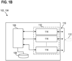
- FIG.1B shows a device 102, 104 in a schematic representation according to various aspects.
- the representation in FIG.1B illustrates exemplary components that enable one device 102, 104 to communicate with another device 102, 104. It is understood that the representation in FIG.1B exemplary and simplified for purposes of illustration and that a device 102, 104 may include additional or alternative components than those shown.
- the device 102, 104 may include a processor 106, a storage device 108 (illustratively, a memory), and one or more communication interfaces 110.
- the device 102, 104 may include multiple (e.g., narrowband) communication interfaces.
- the device 102, 104 may include a single communication interface 110.
- the device 102, 104 may have one or more communication interfaces 110 that cover only a portion of the spectrum but can quickly change frequency. It is understood that the aspects described with respect to multiple communication interfaces may also apply to a single communication interface, and vice versa.
- the processor 106 may be configured to control an operation of the device 102, 104, e.g., the processor 106 may be configured to control a transmission/reception of data 112 via the communication interfaces 110.
- the storage device 108 may be configured to store data received at the device 102, 104 and/or data to be transmitted from the device 102, 104. Additionally or alternatively, the device 108 may be configured to store instructions executed by the processor 106.
- Each communication interface 110 may include one or more components that enable the device 102, 104 to send/receive data 112 (generally data-carrying signals).
- a communication interface 110 may thus include one or more components that enable encoding/decoding of analog signals for transmission/reception over a physical medium.
- a physical communication channel can thus be a wired communication channel (e.g. implemented as a wire, optical fiber and the like) or a wireless communication channel (e.g. a radio channel via
- the components of the communication interfaces 110 can thus be selected depending on the type of communication, e.g. for sending/receiving electrical signals via a wire, optical signals via an optical fiber, radio signals via the air, etc.
- a "spectral resource" can describe a section of the frequency spectrum over which the communication is carried out wired or wirelessly.
- wireless communication As it may be the most important use case for the strategy described herein (e.g. for flexible control of multiple actuators in a control system). Therefore, some terms may refer to the wireless context, e.g. to certain wireless technologies (such as WiFi, Bluetooth, etc.). However, it is understood that the aspects and terms described with regard to wireless communication may also apply to wired communication in a corresponding manner and vice versa.
- each communication interface 110 may include a transceiver circuit 114 (illustratively, a transceiver chip or a transceiver chain).
- a transceiver circuit 114 may be configured to transmit/receive data 112 according to a wired or wireless communication standard.
- a transceiver circuit 114 may thus include analog and/or digital components configured to perform transmit/receive operations according to a particular communication technology.
- a transceiver circuit 114 may be configured according to a WLAN communication protocol or standard (e.g., IEEE 802.11).
- a transceiver circuit 114 may be configured according to the Bluetooth standard, the Zigbee standard, the 3G, 4G, 5G and/or 6G cellular communication standards, and the like.
- a transceiver circuit 114 may be configured according to a power line communication protocol, eg, according to the one-wire communication protocol.
- each communication interface 110 may include a WLAN modem.
- a transceiver circuit 114 may include an antenna (not shown) or may be coupled to an antenna, e.g., a single antenna or an antenna array, and may transmit and/or receive radio frequency signals using the corresponding antenna.
- a transceiver circuit 114 is an RF transceiver.
- a transceiver circuit 114 may include one or more amplifiers (e.g., power amplifiers, low noise amplifiers) to amplify a signal received or to be transmitted using the associated antenna.
- a transceiver circuit 114 may include one or more frequency converters, e.g., to convert the frequency of a received signal from the radio frequency range to a baseband range or to convert the frequency of a signal to be transmitted from the baseband range to a radio frequency range.
- a transceiver circuit 114 may include one or more filters and mixers to select a desired frequency or frequency range for transmitting/receiving radio signals.
- the communication interfaces 110 may be configured according to the same communication technology.
- the device 102, 104 may be configured to communicate with more than one communication technology, such that the communication interfaces 110 (and the processor 106) may comprise separate elements (e.g., separate sets of Transceiver circuits 114) configured for different communication technologies.
- the processor 106 may be configured for signal processing to enable the transmission/reception of data 112 via the communication interfaces 110.
- the processor 106 may include a baseband modem (in this scenario, the base modem may implement the functions of the communication interface 110 or transceiver circuits 114).
- the processor 106 may be provided without a base modem, but may be configured to control the communication interfaces 110 or the transceiver circuits 114 according to coding, scheduling, multiplexing, etc., as defined in the respective communication protocols.
- the processor 106 may be configured to perform processing at different levels, e.g., at the physical level, the data link level, the network level, etc., up to the application level.
- each modem (such as a WLAN dongle) may have a transceiver with its own processor that covers the physical layer down to the network layer.
- FIG.1A and FIG.1B show a general exemplary context in which the communication strategy proposed here can be implemented. Such a communication strategy is described in relation to the FIG.2 to FIG.6 described in detail. However, as already mentioned, the application of the communication strategy is not limited to a network as in FIG.1A shown, or on devices such as those shown in FIG.1A and FIG.1B but can generally be applied in any suitable communication scenario to achieve high reliability.
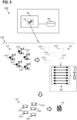
- FIG.2 shows a network manager 200 in a schematic view according to various aspects.
- the network manager 200 may include a processor 202 and a memory 204 coupled to the processor 202.
- the memory 204 may be configured to store instructions (e.g., software instructions) to be executed by the processor 202.
- the instructions may cause the processor 202 to perform a customized resource allocation method 210, which will be described in more detail below. Aspects described with respect to a configuration of the processor 202 may also apply to the method 210, and vice versa.
- a network manager may also be referred to herein as a resource allocator or resource distributor.
- the network manager 200 may be a dedicated device in a communication network (e.g., in the communication network 100).
- the network manager 200 may be physically located in the communication network, e.g., in the LAN or WLAN, or it may be located elsewhere (illustratively, in the "cloud") and communicatively coupled to the network participants.
- the functions of the network manager 200 may be implemented by one of the devices involved in the communication, e.g., by the network device 212.
- the network manager 200 may be configured according to the method 210 to control (eg, to instruct) an allocation of spectral resources 216 between a plurality of client devices 214 for communication with a network device 212.
- the method 210 may be applied to any type of client devices 214 and network devices 212.
- the network device 212 may be configured like the first device 102, and the client devices 214 may be configured like the second device 104, which may be configured with respect to FIG.1A and FIG.1B
- the network device 212 may be a base station (e.g., a controller) and a client device 214 may be an automated machine (e.g., a
- the base station 212 may include the network manager 200 or may be configured to implement the function of the network manager.
- a system is shown having five client devices 214-1...214-5.
- the strategy described herein may be applied in scenarios having any suitable number of client devices 214, e.g., two, three, four, five, ten, or more than ten.
- the system may generally have more than one network device 212, and the network manager 200 may be configured to control the allocation of the spectral resources 216 for communication of the client devices 214 with each of the network devices 212.
- the network manager 200 may be configured to assign to each client device 214 one or more spectral resources 216 by means of which the client device 214 can communicate with the network device 212 (e.g., exchange data with the network device 212).
- the network manager 200 may thus be configured to define how the spectral resources 216 available for communication with the network device 212 can be distributed among the client devices 214.
- a spectral resource 216 may be or include a portion of the frequency spectrum available for communication with the network device 212, eg, a portion of the frequency spectrum in which the network device 212 can receive/transmit signals (eg, radio signals).
- the network manager 200 may thus be configured to define an allocation of the available portions of the frequency spectrum to the client devices 214.
- the allocation of the spectral resources 216 may be adapted to ensure reliable operation of the network, e.g., the allocation may be arranged to reduce (e.g., minimize) the possibility of a failure of one of the client devices 214.
- the allocation may be arranged to reduce (e.g., minimize) the possibility that a client device 214 may not be able to communicate with the network device 212 (e.g., due to excessively degraded quality of communication).
- the strategy described herein may thus ensure stable and reliable operation of the individual client devices 214 as well as the system as a whole.
- the allocation may be arranged according to a max-min criterion based on maximizing the communication quality for the client device with the worst communication conditions.
- a resource allocation according to the max-min criterion can maximize the quality of communication (e.g., the signal-to-noise ratio) of the weakest user in the system.
- the weakest user with respect to the current time window (also referred to as a time slot) can be determined depending on the respective channel realizations of the resources allocated to the user, which in turn can depend on the allocation.
- the processor 202 can be configured to perform an iterative allocation procedure 230.
- the processor 202 can be configured to perform the iterative allocation procedure 230 to allocate to each client device 214 one or more spectral resources 216 available for communication with the network device 212.
- the allocation procedure 230 can also be referred to as an allocation method, allocation procedure, or assignment procedure.
- the iterative assignment procedure 230 may comprise at least one iteration, e.g. a plurality of iterations. An iteration may also be referred to herein as an instance (e.g.
- the processor 202 may be configured to allocate one of the available spectral resources 216 to one of the client devices 214 in each iteration, as described in further detail below.
- the processor 202 may be configured to perform an allocation procedure 230 (illustratively, all iterations) during a predetermined time window (see also FIG.4 ), eg, a predetermined period of time.
- the processor 202 may be configured to then perform another allocation procedure 230 in another time window, etc.
- the processor 202 may be configured to determine (or receive), in each iteration, a plurality of quality factors 218 associated with the plurality of client devices 214.
- the processor 202 may be configured to determine a respective quality factor 218 for each of the client devices 214 (e.g., first through fifth quality factors 218-1...218-5 in the example scenario of FIG.2A).
- the processor 202 may be configured to determine for each client device 214 a plurality of quality factors, illustratively one quality factor for each client-network combination.
- a quality factor 218 may represent a quality of the communication of the respective client device 214 (eg during the current time window).
- a quality factor 218 may represent an overall quality with which the client device 214 can utilize the available spectral resources 216.
- a quality factor 218 of a client device 214 may represent a communication quality of one or more channel implementations 220 between the client device 214 and the network device 212 (as shown by way of example in FIG.2A for a first client device 214-1).
- a channel implementation 220 between a client device 214 and the network device 212 can be or have a communication path (in other words, a propagation path) for a respective spectral resource 216.
- a channel implementation 220 can thus be or have a communication path in a corresponding section of the frequency spectrum, e.g. a communication path via which signals are sent/received in a corresponding frequency range.
- a channel implementation 220 can thus represent an actual communication path (an actual communication connection) between a client device 214 and the network device 212, e.g. with respect to a corresponding spectral resource 216, e.g. in a corresponding frequency range.
- a quality factor 218 of a client device 214 can thus represent an overall quality of the available channel realizations 220 between the client device 214 and the network device 212.
- the quality factor 218 can represent a quality of the available communication paths between the client device 214 and the network device 212 for the available spectral resources 216.
- a quality factor 218 may represent a quality of communication for a client device 214 with respect to the not yet allocated spectral resources 216 (e.g. during the current time window).
- the quality factor 218 in this configuration may represent a quality with which the respective client device 214 can use the still free (not yet allocated) spectral resources 216.
- a quality factor 218 may determine a quality of communication for a client device 214 with respect to all available spectral Represent resources 216 for communication with the network device 212, regardless of whether the spectral resources 216 have already been allocated (e.g. during the current time window).
- the quality factor 218 can clearly represent a quality with which the respective client device 214 can use all spectral resources 216 that are in principle available (both "active" and "inactive").
- a quality factor 218 There may be different ways to express a quality factor 218, e.g. different ways to represent a general resource quality (or channel quality) of a client device 214. Three examples are given below that enable an efficient understanding of the communication scenario of a client device 214. However, it is understood that in principle other ways to represent a quality factor 218 can also be provided.
- the quality factor 218 of a client device 214 may correspond to the greatest channel quality among the channel qualities of the channel realizations 220 between the client device 214 and a network device 212.
- the quality factor 218 of a client device 214 may be or correspond to the greatest signal-to-noise ratio among the signal-to-noise ratios of the channel realizations 220 between the client device 214 and the network device 212.
- the quality factor 218 of a client device 214 may comprise or correspond to a combination of a subset of the channel qualities of the channel implementations 220 between the client device 214 and the network device 212.
- the quality factor 218 of a client device 214 may represent more than one channel realization 220.
- the quality factor 218 of a client device 214 may be representative of a number N of channel realizations 220, where N is less than the total number of channel realizations 220 between the client device 214 and the network device 212.
- the quality factor 218 may represent an overall quality of the best channel realizations 220 available to the client device 214, e.g., based on the assumption that these channel realizations 220 are most relevant for the communication.
- the subset of channel qualities may include the greatest channel quality, the second greatest channel quality, the third greatest channel quality, and so on, up to the Nth greatest channel quality among the channel qualities of the channel implementations 220 of the client device 214.
- a quality factor 218 based on a combination (e.g., a sum) of such channel qualities may more accurately represent the scenario for the client device 214 compared to the "single channel" configuration.
- the quality factor 218 in this configuration may be or comprise a sum of the signal-to-noise ratios of the corresponding channel realizations 220 that are considered in the subset.
- the quality factor 218 may be or comprise a sum of the largest signal-to-noise ratio, the second largest signal-to-noise ratio, etc., up to the Nth largest signal-to-noise ratio.
- the values of the signal-to-noise ratios can be offset in the linear range. (visual, according to a linear scale), which allows easy calculation (sum or product).
- the number N of channel realizations 220 to be considered may be chosen depending on the desired functionality of the system. A higher N may provide a more comprehensive view of the communication scenario of a client device 214, while a smaller N may allow for easier analysis and allocation. As a numerical example, the number N may be equal to or greater than 2, e.g. equal to or greater than 5. As another example, the number N may comprise at least 25% of all available channel realizations 220 for a client device 214, e.g. at least 50%, e.g. at least 75%. In a preferred configuration that may yield an optimal result in terms of allocation efficiency, the number N may depend on the maximum number of resources to be allocated per client device. For example, the number N may be between 100% and 150% of the maximum number of resources to be allocated per client device.
- the number N of channel realizations 220 to be considered may be the same for each client device 214. However, in some aspects, a different number of channel realizations 220 may be considered for different client devices 214, e.g., taking into account other factors such as proximity to the network device 212, relevance of the operation to be performed by the client device 214, and the like.
- the quality factor 218 may be or comprise a product.
- the quality factor 218 of a client device 214 may comprise a product of a first factor and a second factor.
- the first factor may be the greatest channel quality among channel qualities of the channel realizations 220 between the client device 214 and the network device 212.
- the second factor may comprise the Nth greatest channel quality among channel qualities of the channel realizations 220 between the client device 214 and the network device 212.
- the quality factor 218 may be more sensitive to variations in the quality of communication over the channel realizations 220.
- the first factor may have the largest signal-to-noise ratio among the channel realizations 220 of the client device 214
- the second factor may have the Nth largest signal-to-noise ratio among the channel realizations 220 of the client device 214.
- two values are considered, namely the best (largest) value and another value (the Nth value).
- the another value may be the second best channel quality (e.g., the second largest signal-to-noise ratio).
- the another value may have the worst channel quality (e.g., the lowest signal-to-noise ratio) for the client device.
- the another value may be the value in position "N" (e.g., in a preference list of the client device), where N may be selected based on the considerations described above.
- the processor 202 may be configured, in each iteration, to allocate one of the available (and not yet allocated) spectral resources 216 to one of the client devices 214 based on the determined (or received) quality factors 218. According to the adapted strategy described herein, the processor 202 may be configured to allocate one of the available (and not yet allocated) spectral resources 216 to the client device 214 having the lowest quality factor 218 associated therewith (e.g., the lowest signal-to-noise ratio in the corresponding channel realizations 220).
- the processor 202 may be configured to allocate one of the available (and not yet allocated) spectral resources 216 to the client device 214 having the lowest quality factor 218 associated therewith (e.g., the lowest signal-to-noise ratio in the corresponding channel realizations 220). assigns a spectral resource 216 (e.g. a subchannel) to the lowest quality factor 218 in the current iteration.
- the lowest quality factor 218 e.g., the lowest signal-to-noise ratio in the corresponding channel realizations 220.
- This approach may be based on the realization that it may be less critical to allocate spectral resources 216 to client devices 214 with good communication quality (e.g., high quality channel implementations 220, e.g., with low noise, low interference, etc.) since the overall reliability of the system may only be weakly influenced by such devices.
- good communication quality e.g., high quality channel implementations 220, e.g., with low noise, low interference, etc.
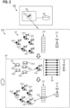
- FIG.2 the allocation of a first spectral resource 216-1 to the first client device 214-1 is shown.
- the processor 202 may be configured to select which of the available (and not yet allocated) spectral resources 216 should be allocated to the client device 214-1 with the lowest quality factor 218-1 to ensure reliable operation of the system.
- the processor 202 may be configured to allocate to the client device 214-1 with the lowest quality factor 218-1 the spectral resource 216 for which the corresponding channel implementation 220 has the highest quality, e.g., the highest signal-to-noise ratio. This allocation ensures that the weakest user is allocated his preferred spectral resource 216-1 (e.g., his preferred channel or subchannel), thereby maximizing reliability for that user.
- the processor 202 may be further configured to perform further iterations of the assignment procedure 230, to allocate additional (remaining) spectral resources 216 to the client devices 214. In each iteration, the processor 202 may take into account the quality factors 218 determined in the first iteration of the method 230, or, in other aspects, the processor 202 may be configured to determine new (updated) quality factors 218 in each iteration. Updating the quality factors 218 may enable a more resource-intensive but more accurate allocation process.
- the processor 202 may be configured to allocate, in a second iteration of the allocation procedure 230, another (not yet allocated) spectral resource 216 to another (second) client device 214 having the lowest quality factor 218 for this iteration. In a third iteration of the allocation procedure 230, the processor 202 may allocate another (not yet allocated) spectral resource 216 to another (third) client device 214 having the lowest quality factor 218 for this iteration, etc.
- the allocations made in different iterations may be independent of each other.
- the processor 202 may allocate the corresponding spectral resource 216 to a client device 214 that has already been allocated one or more spectral resources 216 or to a client device 214 that has not yet been allocated spectral resources 216.
- the processor 202 may be configured to allocate at least one spectral resource 216 to each client device 214 before allocating further spectral resources 216 to client devices 214 that have already been allocated a spectral resource 216. In this way, the client devices 214 may be enabled to perform a respective operation more quickly, for example.
- the processor 202 may be configured to allocation during an iteration to ignore the client device to which the spectral resource 216 was allocated in the previous allocation iteration. More generally, the processor 202 may be configured to ignore the client devices that already have an allocated spectral resource 216 when there are client devices 214 without an allocated spectral resource 216 when allocating during an iteration.
- the processor 202 may be configured to allocate the spectral resources 216 regardless of whether one or more client devices 214 do not have an allocated spectral resource 216.
- a client device 214 may be allocated a plurality of spectral resources 216 before another client device 214 is allocated its first spectral resource 216. This approach provides a more favorable allocation for the weaker users and thus may ensure more reliable communication overall.
- a client device 214 may be allocated more than one spectral resource 216 (e.g., during a time window).
- the processor 202 may be configured to allocate a spectral resource 216 to a client device 214 that has already been allocated another spectral resource 216 in one of the previous iterations in at least one iteration of the allocation procedure 230.
- the processor 202 may be configured to perform iterations of the allocation procedure 230 until each client device 214 is allocated at least one spectral resource 216.
- each client device 214 be associated with a maximum number of spectral resources 216 that can be allocated to the client device 214.
- each client device 214 may have a limit on the number of spectral resources 216 that the client device 214 can obtain during an allocation process 230.
- the maximum number of spectral resources 216 that can be allocated to a client device 214 may vary depending on the desired operation of the client device 214. For example, the maximum number of spectral resources 216 may increase if the client device 214 requires a large amount of bandwidth for its operation, or if the client device 214 must exchange large amounts of data for its operation. As another example, the maximum number of spectral resources 216 may decrease if the operation performed by the client device 214 has a low priority within the network (e.g., within the assembly line).
- the maximum number of spectral resources 216 may vary between client devices 214.
- a first client device 214-1 may have a first maximum number M1 of spectral resources 216 that may be allocated to the first client device 214-1
- a second client device 214-2 may have a second maximum number M2 of spectral resources 216 that may be allocated to the second client device 214-2, etc.
- the first maximum number M1 may be different from the second maximum number M2.
- the first maximum number M1 may be equal to the second maximum number M2.
- At least one client device 214 may have a maximum number of spectral resources 216 that may be allocated to the client device 214 that is different from the maximum number of spectral resources 216 that may be allocated to another client device 214. In various aspects, at least one client device 214 may have a maximum number of spectral resources 216 that can be allocated to the client device 214 that is equal to the maximum number of spectral resources 216 that can be allocated to another client device 214.
- the processor 202 may be configured to allocate (during the allocation procedure 230) to each client device 214 a number of spectral resources 216 that is equal to or less than the respective maximum number of spectral resources 216 that can be allocated to the client device 214. In this scenario, the processor 202 may be configured to ignore a client device for allocating the spectral resources 216 in each iteration if the client device 214 has (already) been allocated a number of spectral resources 216 that is equal to the respective maximum number of spectral resources 216 that can be allocated to the client device 214.
- the allocation procedure 230 described herein allows the allocation to be completed (with high reliability) with a number of iterations that is orders of magnitude less compared to an exhaustive search.
- an exhaustive search may comprise establishing all possible allocations of resources to users and evaluating the combined channel quality of the worst user.
- a client device 214 may provide feedback data to the network device 212 using the allocated spectral resources 216 transmit and/or receive instructions from the network device 212 using the associated spectral resources 216.
- the instructions may be associated with a task performed by the client device 214.
- the processor 202 may be configured to generate (or receive, see also FIG.5 ) associated with the client devices 214 (e.g., first through fifth preference lists 302-1...302-5 in the exemplary scenario in FIG.3 ).
- a preference list 302 may be a channel list comprising the channel realizations 220 of the corresponding client device 214 in order of preference.
- a preference list 302 may thus provide a direct and compact representation of the spectral resources 216 preferred by a client device 214.
- the processor 202 may be configured to determine (e.g., generate or, in some aspects, receive) a corresponding preference list 302 for each client device 214 in at least one iteration of the allocation procedure.
- the processor 202 may be configured to determine the preference lists 302 in each iteration to provide a dynamic understanding of how the spectral resources 216 should be allocated, or once (e.g., at the first iteration) to provide a less resource intensive allocation process.
- a preference list 302 of a client device 214 may include or represent the respective channel realizations 220 between the client device 214 and the network device 212, ordered by channel quality.
- a preference list 302 may include the channel realizations 220 ordered by decreasing channel quality, as in the example configuration in FIG.3 for the first preference list 302-1.
- This representation may directly indicate the preferred channel implementation 220 (and correspondingly the spectral resource 216) for a client device 214, illustratively at the first position in the list.
- a preference list 302 may also have the channel implementations 220 ordered according to a different criterion, e.g., in ascending order of channel quality.
- a preference list 302 can include the channel realizations 220 ordered by signal-to-noise ratio, e.g., ordered by decreasing signal-to-noise ratio (or, in other aspects, by increasing signal-to-noise ratio).
- the processor 202 may be configured to allocate, in each iteration, a spectral resource 216 to the client device 214 with the smallest quality factor 218 based on the respective preference list 302.
- the processor 202 may be configured to allocate to the client device 214 the spectral resource 216 that corresponds to the preferred channel implementation 220 in the respective preference list 302 (e.g., the first, in the case of an order of decreasing channel quality).
- the processor 202 may be configured to remove a channel realization corresponding to an assigned spectral resource 216 from each preference list 302. This may result in only the channel realizations 220 remaining in the preference lists 302 that correspond to the spectral resources 216 that still need to be assigned, thereby simplifying the assignment procedure 230.
- the processor 202 may be configured to be configured to remove the channel realization 220 corresponding to this spectral resource 216-1 from each preference list 302 of the client devices 214.
- a preference list 302 may represent a reordered set (or subset) of the available spectral resources 216 (based on the corresponding channel realizations 220) and may become smaller with each iteration as the spectral resources 216 are allocated.
- the processor 202 may re-determine (e.g., generate or receive) the (complete) preference lists 302 for a new allocation procedure 230.
- a preference list 302 of a client device 214 may additionally or alternatively be considered to determine the quality factor 218 of the client device.
- a quality factor 218 may comprise or represent a combination (e.g., a sum) of the channel qualities of a subset of channel implementations 220, or it may be a product.
- the quality factor 218 may be based on a combination of the first N entries of the preference list 302.
- the quality factor 218 may be based on a combination of the last N entries of the preference list 302.
- the processor 202 may be configured to perform (and complete) the allocation procedure 230 within a predetermined time window and then start a new allocation procedure in another time window.
- This scenario is shown in FIG.4 for an example case with three client devices 214-1, 214-2, 214-3 and five time slots 402-1...402-5, but it is understood that the data relating to FIG.4 described aspects may be applied to a scenario with any suitable number of time slots and any number of client devices 214.
- the processor 202 may be configured to repeat the allocation procedure 230 in predefined time windows.
- the processor 202 may be configured to initiate and complete the allocation procedure 230 within a time window 402-1 and then repeat the allocation procedure 230 in one or more subsequent time windows 402-2...402-5.
- a time window may be understood as a predetermined period of time in which each client device 214 should be allocated at least one spectral resource 216.
- the duration of a time window may be chosen according to the desired operation of the network. As a numerical example only, a time window may have a duration in the range of 1 ms to 100 ms.
- a time window may also be referred to herein as an allocation period.
- each client device 214 may use each allocated period to exchange data with the network device 212.
- the processor 202 may be configured to allocate at least one spectral resource 216 to each client device 214 during each time slot. This is in FIG.4 for the three client devices 214-1...214-3, each of which is allocated one or more spectral resources 216 (shown by a corresponding fill) during each of the time slots 402-1...402-5.
- FIG.4 clearly shows the frequency-related properties of the spectral resources 216 (along the vertical axis in FIG.4 ).
- each spectral resource 216 may cover a corresponding spectral range 404 (illustratively) within a predefined bandwidth 406 in the frequency range available for communication with the network device 212.
- the spectral range 404 as well as the predefined bandwidth 406 may be selected depending on the communication technology under which the client devices 214 and network device 212 are configured.
- the frequency band may comprise the 2.4 GHz frequency band, or the 3.7 GHz band, or the 5 GHz frequency band, or the 6 GHz frequency band.
- the spectral range for each spectral resource 216 may have the same width (with different lower and upper limits).
- the spectral resources 216 e.g., subchannels
- a first spectral range of a first spectral resource 216 may have a first bandwidth and a second spectral range of a second spectral resource 216 may have a second bandwidth equal to the first bandwidth.
- the bandwidth in the frequency domain of a spectral resource 216 may have a width in the range of 0.1 MHz to 20 MHz, for example a width of 2 MHz.
- a division of the spectral resources 216 into frequency ranges of equal width can enable a simpler and reproducible assignment. However, it is understood that the different spectral resources 216 can in principle have different bandwidths.
- the spectral resources 216 available for communication between a client device 214 and the network device 216 may be orthogonal to each other in frequency.
- the orthogonality may ensure that interference between different users is reduced (or eliminated).
- the evaluation of the communication quality of the client devices 214 may be based on information provided by the client devices 214, as described with respect to FIG.5 described.
- FIG.5 shows a network monitor 500 in a schematic view, according to various aspects.
- the network monitor 500 may include a processor 502 and a memory 504 coupled to the processor 502.
- the memory 504 may be configured to store instructions (eg, software instructions) executed by the processor 502.
- the instructions may cause the processor 502 to perform a method 510 for monitoring communication quality in a communication network, which will be described in more detail below. Aspects described with respect to a configuration of the processor 502 may also apply to the method 510 and vice versa.
- network monitor 500 may be a dedicated device in a communications network (e.g., communications network 100).
- the functions of network monitor 500 may be implemented by one of the devices involved in the communication, e.g., network device 212.
- network monitor 500 and network manager 200 may be combined into a single device that performs both functions (e.g., the functionality of processor 502 may be performed by processor 202 and vice versa).
- the network monitor 500 may be configured to determine the quality factors for the client devices 214 of the communication network.
- the network monitor 500 may be further configured to determine (eg, generate) the preference lists of the client devices 214 of the communication network.
- the network monitor 500 may then use the result of its operation to allocate spectral resources 216 to the client devices 214, or it may communicate the result of its operation to a network manager (e.g., network manager 200) to direct the allocation of spectral resources 216 to the client devices 214.
- network monitor 500 may provide an output 504 representing the quality factors 218 associated with the client devices 214.
- output 504 may further comprise or represent the preference lists of the client devices 214.
- the processor 502 may be configured according to the method 510 to receive channel state information 502 from the client devices 214, eg from at least one client device 214, eg from each client device 214.
- the processor 502 may receive first to fifth channel state information 502-1...502-5.
- the channel state information 502 of a client device 214 may include or represent a channel quality of each channel realization 220 between the (respective) client device 214 and the network device 212. This is in FIG.5 for example, with respect to the first channel state information 502-1 associated with the first client device 214-1.
- the channel state information 502 of a client device 214 may depend on various factors that may affect the communication between the client device 214 and the network device 212, e.g., various factors that may affect the channel realizations 220 (illustratively, the physical propagation paths) between the client device 214 and the network device 212.
- the channel state information 502 may depend on a relative position of the client device 214 with respect to the network device 212.
- the channel state information 502 may depend on interference, that the client device 214 experiences in its channel realizations 220.
- Reference signals may be used to determine the channel state information 502, e.g., the channel quality, of the channel implementations 220.
- the processor 502 may be configured, for at least one (e.g., for each) client device 214, to control a transmission of reference signals via each of the respective channel implementations 220.
- the processor 502 may be configured, for one (e.g., for each) client device 214, to control the transmission of a first reference signal via a first channel implementation 220, the transmission of a second reference signal via a second channel implementation 220, etc.
- a reference signal may clearly be a pilot signal used to determine the channel quality.
- a reference signal may be or include a so-called sounding reference signal (SRS).
- SRS sounding reference signal
- the processor 502 may be configured to perform the transmission of the reference signals.
- the processor 502 may be configured to control (e.g., instruct) the network device 212 to transmit the reference signals to the client device(s) 214.
- a base station may transmit sounding reference signals (SRS) that are distributed across the entire available spectrum. These can already be found, for example, in existing standards such as LTE and 5G.
- SRS sounding reference signals
- 802.11 802.11
- each data packet is preceded by a preamble for channel estimation.
- the channel state information 502 may include a reception quality of each reference signal. Clearly, the channel information may be determined based on a reception quality of the reference signals, eg at the client devices 214. In this regard, the processor 502 may be configured to determine the reception quality, or to receive such information from the client devices 214. In a preferred configuration, the processor 502 may be configured to receive respective channel state information 512 from each client device 214, eg based on a corresponding reception of reference signals by means of the respective channel realizations 220. Clearly, the individual users can estimate their channel quality on the respective frequencies using the SRS and send the result back (eg back to the base station).
- the channel state information 512 for a client device 214 may include a first channel quality of a first channel implementation 220 based on receipt of the first reference signal, a second channel quality of a second channel implementation 220 based on receipt of the second reference signal, etc.
- the channel state information 512 for each client device 214 may include: a respective packet loss rate using each of the channel implementations 220; a respective signal-to-noise ratio in each of the channel implementations 220; a signal level of another data transmission in each of the channel implementations 220; and/or the like.
- the processor 502 may be configured to determine the quality factors 218 of the client devices 214 based on the received channel state information 512.
- the processor 502 may be configured to determine (eg, calculate) the quality factor 218 of a client device 214 as the highest channel quality of the channel realizations 220 based on the received channel state information 512.
- the processor 502 may be configured to determine the quality factor 218 a client device 214 as the largest signal-to-noise ratio among the channel realizations 220.
- the processor 502 may be configured to determine (e.g., calculate) the quality factor 218 of a client device 214 as a combination of a subset of the channel qualities of the channel implementations 220 based on the received channel state information 512.
- the processor 502 may be configured to determine (e.g., calculate) the quality factor 218 of a client device 214 as a sum of the N largest signal-to-noise ratios among the channel implementations 220 (where N is equal to or greater than 2).
- the processor 502 may be configured to determine (e.g., calculate) the quality factor 218 of a client device 214 as the product between the largest signal-to-noise ratio and the Nth largest signal-to-noise ratio among the channel realizations 220.
- the processor 502 may additionally or alternatively be configured to determine (e.g., calculate or generate) a preference list for at least one (e.g., each) client device 214 based on the received channel state information 512.
- the processor 502 may be configured to order the channel realizations 220 of a client device 214 according to the respective channel quality, e.g., according to the respective signal-to-noise ratio.
- the processor 502 may be configured to determine a preference list of a client device 214 by ordering the respective channel realizations 220 according to decreasing channel quality, e.g., according to decreasing signal-to-noise ratio.
- other criteria may also be provided, e.g., ordering according to increasing channel quality (e.g., according to increasing signal-to-noise ratio), as another example.
- the processor 502 may be configured to determine the quality factors 218 (and/or the preference lists) at the beginning of an assignment procedure and/or during an assignment procedure in order to adapt the quality factors 218 (and/or the preference lists) if the quality of the communication has changed.
- the output signal 514 may indicate for each client device 214 which channel realization 220 (and correspondingly which spectral resources) or which channel realizations 220 are to be used for the transmission of data.
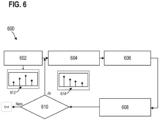
- FIG.6 shows a schematic flow diagram of a method 600 for allocating spectral resources in a communication network.
- the method 600 may include aspects described with respect to the network manager 200 and the network monitor 500 (eg, aspects related to the methods 210, 510).
- the method 600 may be understood as an iterative algorithm for allocating spectral resources according to a max-min criterion for improving the reliability of a system.
- the method 600 may include receiving (or determining) channel state information for each client device of a plurality of client devices at 602.
- the method 600 may include receiving information representing the signal-to-noise ratio for the channel realizations between each client device and a network device.
- the method 600 may include obtaining the observed signal-to-noise ratio of each user for each channel realization (e.g., for each subchannel).
- the method 600 may include receiving the channel state information at a network device (e.g., a base station) from each of the client devices.
- the channel state information may be in the form of an unordered list 612 of the channel realizations (e.g., the subchannels), e.g., a list comprising the channel realizations and the corresponding signal-to-noise ratio.
- the list 612 may comprise the channel realizations simply ordered by number (e.g., first, second, etc.), e.g., ordered by the corresponding frequency range, but not ordered by the channel quality (e.g., not ordered by the signal-to-noise ratio).
- the method 600 may further comprise, in 604, determining (eg, calculating or generating) a preference list 614 for each client device based on the received channel status information.
- the method may comprise sorting the channel realizations (eg, subchannels) of a client device by channel quality (eg, by descending signal-to-noise ratio) to determine a preference list for the client device. This is in FIG.6 with the preference list 614 in which the channel implementations are ordered by descending signal-to-noise ratio to create a preference list 614 for a corresponding client device.
- the method 600 may further comprise, in 606, determining (e.g., calculating or receiving) a quality factor for each client device (illustrated for each user).
- the method 600 may comprise determining the quality factor of a client device based on the received channel state information (and/or based on the preference list) for the client device.
- the method 600 may comprise determining the quality factor in any suitable manner as described above, e.g., as a largest signal-to-noise ratio, as a sum of the signal-to-noise ratios of a subset of N channel implementations, or as a product between the largest signal-to-noise ratio and the Nth largest signal-to-noise ratio of the channel implementations.
- the method 600 may further comprise, in 608, allocating a spectral resource (e.g., a subchannel) to the client device with the lowest quality factor (illustratively, the user with the lowest communication quality).
- the method 600 may comprise allocating the preferred spectral resource to the client device with the lowest quality factor, e.g., the spectral resource corresponding to the channel realization with the highest channel quality for that client device (e.g., the channel realization with the greatest signal-to-noise ratio, e.g., the first resource in the preference list).
- the method 600 may further comprise removing the allocated spectral resource from the preference lists of the client devices, e.g., removing the corresponding channel realizations from the preference lists.
- the method 600 may further comprise, at 610, determining whether there is at least one client device with an incomplete association. If yes (Yes in 610), the method 600 may return to 604 and perform another association. If no (No in 610), the method 600 may terminate. For example, the method 600 may be performed within a time window, and another iteration of the method 600 may be performed in another time window.
- a computer program product comprising instructions that, when the program is executed by a computer, cause the computer to perform any of the methods described herein (e.g., methods 210, 510, 600).
- data may include information in any suitable analog or digital form, e.g. in the form of a file, a section of a file, a set of files, a signal or stream, a portion of a signal or stream, a set of signals or streams, and the like.
- data can be used to denote a reference to information, e.g. in the form of a pointer.
- data is not limited to the above examples and can take various forms and represent any information as understood in the art.
- memory may be understood as a computer-readable medium (e.g., a non-transitory computer-readable medium) in which data or information can be stored for retrieval. References to “memory” herein may therefore be understood to refer to volatile or non-volatile memory, including random access memory (RAM), read-only memory (ROM), flash memory, solid state memory, magnetic tape, hard disk drive, optical drive, and others, or any combination thereof. Registers, shift registers, processor registers, data buffers, etc. are also included herein under the term memory.
- software refers to all types of executable instructions, including firmware.
- a device corresponding to a method described in detail herein may comprise one or more components configured to carry out each aspect of the associated method.
Landscapes
- Engineering & Computer Science (AREA)
- Computer Networks & Wireless Communication (AREA)
- Signal Processing (AREA)
- Quality & Reliability (AREA)
- Mobile Radio Communication Systems (AREA)
Applications Claiming Priority (1)
| Application Number | Priority Date | Filing Date | Title |
|---|---|---|---|
| DE102022134168.2A DE102022134168A1 (de) | 2022-12-20 | 2022-12-20 | Qualitätsbasierte Ressourcenzuordnung in einem Kommunikationsnetzwerk |
Publications (1)
| Publication Number | Publication Date |
|---|---|
| EP4391686A1 true EP4391686A1 (fr) | 2024-06-26 |
Family
ID=89385970
Family Applications (1)
| Application Number | Title | Priority Date | Filing Date |
|---|---|---|---|
| EP23217713.9A Pending EP4391686A1 (fr) | 2022-12-20 | 2023-12-18 | Attribution de ressources basée sur la qualité dans un réseau de communication |
Country Status (2)
| Country | Link |
|---|---|
| EP (1) | EP4391686A1 (fr) |
| DE (1) | DE102022134168A1 (fr) |
Citations (1)
| Publication number | Priority date | Publication date | Assignee | Title |
|---|---|---|---|---|
| US20090164638A1 (en) * | 2007-12-24 | 2009-06-25 | Electronics And Telecommunications Research Institute | System and method for uplink resource allocation in mobile internet |
Family Cites Families (2)
| Publication number | Priority date | Publication date | Assignee | Title |
|---|---|---|---|---|
| CN101933355A (zh) | 2008-01-30 | 2010-12-29 | 夏普株式会社 | 中继装置、通信系统和通信方法 |
| WO2018058352A1 (fr) | 2016-09-28 | 2018-04-05 | Qualcomm Incorporated | Mappage de sous-canaux |
-
2022
- 2022-12-20 DE DE102022134168.2A patent/DE102022134168A1/de active Pending
-
2023
- 2023-12-18 EP EP23217713.9A patent/EP4391686A1/fr active Pending
Patent Citations (1)
| Publication number | Priority date | Publication date | Assignee | Title |
|---|---|---|---|---|
| US20090164638A1 (en) * | 2007-12-24 | 2009-06-25 | Electronics And Telecommunications Research Institute | System and method for uplink resource allocation in mobile internet |
Non-Patent Citations (2)
| Title |
|---|
| RHEE W ET AL: "INCREASE IN CAPACITY OF MULTIUSER OFDM SYSTEM USING DYNAMIC SUBCHANNEL ALLOCATION", VTC 2000-SPRING. 2000 IEEE 51ST. VEHICULAR TECHNOLOGY CONFERENCE PROCEEDINGS. TOKYO, JAPAN, MAY 15-18, 2000; [IEEE VEHICULAR TECHNOLGY CONFERENCE], NEW YORK, NY : IEEE, US, vol. CONF. 51, 15 May 2000 (2000-05-15), pages 1085 - 1089, XP000968037, ISBN: 978-0-7803-5719-8, DOI: 10.1109/VETECS.2000.851292 * |
| TRASL ANDREAS ET AL: "On the Outage Probability of Channel Prediction Enabled Max-Min Radio Resource Allocation", 2022 IEEE WIRELESS COMMUNICATIONS AND NETWORKING CONFERENCE (WCNC), IEEE, 10 April 2022 (2022-04-10), pages 638 - 643, XP034123071, DOI: 10.1109/WCNC51071.2022.9771598 * |
Also Published As
| Publication number | Publication date |
|---|---|
| DE102022134168A1 (de) | 2024-06-20 |
Similar Documents
| Publication | Publication Date | Title |
|---|---|---|
| DE10338053B4 (de) | Verfahren zur Zuweisung von Funkressourcen und Netzeinrichtung in einem Mehrträgerfunkkommunikationssystem | |
| DE112009000561B4 (de) | Koexistenz für an der gleichen Stelle angeordnete Funkgeräte, die in dem gleichen Frequenzband arbeiten | |
| DE60316603T2 (de) | Verfahren und vorrichtung um ein übertragungssignalkennzeichen eines abwärtssignals in einem tdma drahtlosen kommunikationssystem zu verbessern | |
| DE112013002183T5 (de) | Verfahren und Vorrichtungen für opportunistische Funkressourcenzuweisung in Mehr-Träger-Kommunikationssystemen | |
| DE10240138A1 (de) | Dynamische Zuordnung von Funkressourcen in einem Funk-Kommunikationssystem | |
| DE60313611T2 (de) | Verfahren und System zur Berechnung der optimalen Zuordnung von Zeitschlitzen zur Zeile in zellularen Systemen mit Verwendung von Zeilunterteilung | |
| EP2041938B1 (fr) | Réglage de filtre dépendant de l'occupation de la bande adjacente | |
| DE112018005249T5 (de) | Verfahren und Vorrichtungen für Übertragungsleistungssteuerung | |
| DE102016105784B4 (de) | Verfahren und Vorrichtung eines dynamischen Wi-Fi-Multikanalwechsels basierend auf einem Datenverkehrskontext | |
| WO2005043832A1 (fr) | Procede, station radio et produit programme informatique pour l'acces a des ressources radio dans un systeme de communication radio ad hoc | |
| EP1389856A1 (fr) | Procède d'allocation de ressources de radio dans un système de radiocommunication ad-hoc | |
| EP1809058B1 (fr) | Procédé, station de base et station mobile pour minimiser l'interférence dans un système de communication OFDM cellulaire | |
| EP1849324B1 (fr) | Affectation dynamique de ressources dans un systeme de communication a porteuses multiples | |
| EP1623547B1 (fr) | Procédé et dispositif de communication sans fil à porteuses multiple à repartition dynamique de la largeur de frequences et du nombres des sous-bandes | |
| DE102020200973A1 (de) | Verfahren, systeme und vorrichtungen für drahtloskommunikation basierend auf digitalen ofdma-modulationsschemata | |
| DE102013003623A1 (de) | Leistungsbewusste Koexistenz | |
| EP1871125B1 (fr) | Gestion efficient des ressources radio dans un système de radio mobile | |
| EP4391686A1 (fr) | Attribution de ressources basée sur la qualité dans un réseau de communication | |
| WO2004025873A2 (fr) | Procede de transmission de signaux dans un systeme de communication radio | |
| DE102022128254A1 (de) | Zustandsbasierte adaptive Funkressourcenzuweisung | |
| WO2005096552A1 (fr) | Procede pour attribuer des ressources radio pour un reseau local sans fil wlan | |
| EP1716659B1 (fr) | Procede et dispositif pour l'allocation de sous-bandes d'une bande de frequence | |
| DE102021126864A1 (de) | Adaptiver Kanal Sondierung | |
| EP2278843B1 (fr) | Répartition des ressources dans des systèmes de communication sans fil | |
| DE102024206149A1 (de) | Verfahren zum Initiieren einer Übertragung in einem drahtlosen Kommunikationsnetzwerk unter Verwendung eines ausgewählten Modulations- und Codierungsschemas |
Legal Events
| Date | Code | Title | Description |
|---|---|---|---|
| PUAI | Public reference made under article 153(3) epc to a published international application that has entered the european phase |
Free format text: ORIGINAL CODE: 0009012 |
|
| STAA | Information on the status of an ep patent application or granted ep patent |
Free format text: STATUS: THE APPLICATION HAS BEEN PUBLISHED |
|
| AK | Designated contracting states |
Kind code of ref document: A1 Designated state(s): AL AT BE BG CH CY CZ DE DK EE ES FI FR GB GR HR HU IE IS IT LI LT LU LV MC ME MK MT NL NO PL PT RO RS SE SI SK SM TR |
|
| STAA | Information on the status of an ep patent application or granted ep patent |
Free format text: STATUS: REQUEST FOR EXAMINATION WAS MADE |
|
| 17P | Request for examination filed |
Effective date: 20241224 |
|
| RAP1 | Party data changed (applicant data changed or rights of an application transferred) |
Owner name: FUENFEINHALB FUNKSYSTEME GMBH |