EP4391720A2 - Dispositif de chauffage électrique - Google Patents
Dispositif de chauffage électrique Download PDFInfo
- Publication number
- EP4391720A2 EP4391720A2 EP23216152.1A EP23216152A EP4391720A2 EP 4391720 A2 EP4391720 A2 EP 4391720A2 EP 23216152 A EP23216152 A EP 23216152A EP 4391720 A2 EP4391720 A2 EP 4391720A2
- Authority
- EP
- European Patent Office
- Prior art keywords
- heating device
- legs
- ptc element
- electric heating
- frame
- Prior art date
- Legal status (The legal status is an assumption and is not a legal conclusion. Google has not performed a legal analysis and makes no representation as to the accuracy of the status listed.)
- Pending
Links
Images
Classifications
-
- H—ELECTRICITY
- H05—ELECTRIC TECHNIQUES NOT OTHERWISE PROVIDED FOR
- H05B—ELECTRIC HEATING; ELECTRIC LIGHT SOURCES NOT OTHERWISE PROVIDED FOR; CIRCUIT ARRANGEMENTS FOR ELECTRIC LIGHT SOURCES, IN GENERAL
- H05B3/00—Ohmic-resistance heating
- H05B3/02—Details
-
- H—ELECTRICITY
- H05—ELECTRIC TECHNIQUES NOT OTHERWISE PROVIDED FOR
- H05B—ELECTRIC HEATING; ELECTRIC LIGHT SOURCES NOT OTHERWISE PROVIDED FOR; CIRCUIT ARRANGEMENTS FOR ELECTRIC LIGHT SOURCES, IN GENERAL
- H05B3/00—Ohmic-resistance heating
- H05B3/40—Heating elements having the shape of rods or tubes
- H05B3/42—Heating elements having the shape of rods or tubes non-flexible
- H05B3/48—Heating elements having the shape of rods or tubes non-flexible heating conductor embedded in insulating material
- H05B3/50—Heating elements having the shape of rods or tubes non-flexible heating conductor embedded in insulating material heating conductor arranged in metal tubes, the radiating surface having heat-conducting fins
-
- B—PERFORMING OPERATIONS; TRANSPORTING
- B60—VEHICLES IN GENERAL
- B60H—ARRANGEMENTS OF HEATING, COOLING, VENTILATING OR OTHER AIR-TREATING DEVICES SPECIALLY ADAPTED FOR PASSENGER OR GOODS SPACES OF VEHICLES
- B60H1/00—Heating, cooling or ventilating devices
- B60H1/22—Heating, cooling or ventilating devices the heat source being other than the propulsion plant
- B60H1/2215—Heating, cooling or ventilating devices the heat source being other than the propulsion plant the heat being derived from electric heaters
- B60H1/2221—Heating, cooling or ventilating devices the heat source being other than the propulsion plant the heat being derived from electric heaters arrangements of electric heaters for heating an intermediate liquid
-
- F—MECHANICAL ENGINEERING; LIGHTING; HEATING; WEAPONS; BLASTING
- F24—HEATING; RANGES; VENTILATING
- F24H—FLUID HEATERS, e.g. WATER OR AIR HEATERS, HAVING HEAT-GENERATING MEANS, e.g. HEAT PUMPS, IN GENERAL
- F24H1/00—Water heaters, e.g. boilers, continuous-flow heaters or water-storage heaters
- F24H1/0072—Special adaptations
- F24H1/009—Special adaptations for vehicle systems
-
- F—MECHANICAL ENGINEERING; LIGHTING; HEATING; WEAPONS; BLASTING
- F24—HEATING; RANGES; VENTILATING
- F24H—FLUID HEATERS, e.g. WATER OR AIR HEATERS, HAVING HEAT-GENERATING MEANS, e.g. HEAT PUMPS, IN GENERAL
- F24H1/00—Water heaters, e.g. boilers, continuous-flow heaters or water-storage heaters
- F24H1/10—Continuous-flow heaters, i.e. heaters in which heat is generated only while the water is flowing, e.g. with direct contact of the water with the heating medium
- F24H1/12—Continuous-flow heaters, i.e. heaters in which heat is generated only while the water is flowing, e.g. with direct contact of the water with the heating medium in which the water is kept separate from the heating medium
- F24H1/121—Continuous-flow heaters, i.e. heaters in which heat is generated only while the water is flowing, e.g. with direct contact of the water with the heating medium in which the water is kept separate from the heating medium using electric energy supply
-
- F—MECHANICAL ENGINEERING; LIGHTING; HEATING; WEAPONS; BLASTING
- F24—HEATING; RANGES; VENTILATING
- F24H—FLUID HEATERS, e.g. WATER OR AIR HEATERS, HAVING HEAT-GENERATING MEANS, e.g. HEAT PUMPS, IN GENERAL
- F24H3/00—Air heaters
- F24H3/02—Air heaters with forced circulation
- F24H3/04—Air heaters with forced circulation the air being in direct contact with the heating medium, e.g. electric heating element
- F24H3/0405—Air heaters with forced circulation the air being in direct contact with the heating medium, e.g. electric heating element using electric energy supply, e.g. the heating medium being a resistive element; Heating by direct contact, i.e. with resistive elements, electrodes and fins being bonded together without additional element in-between
- F24H3/0429—For vehicles
-
- F—MECHANICAL ENGINEERING; LIGHTING; HEATING; WEAPONS; BLASTING
- F24—HEATING; RANGES; VENTILATING
- F24H—FLUID HEATERS, e.g. WATER OR AIR HEATERS, HAVING HEAT-GENERATING MEANS, e.g. HEAT PUMPS, IN GENERAL
- F24H3/00—Air heaters
- F24H3/02—Air heaters with forced circulation
- F24H3/04—Air heaters with forced circulation the air being in direct contact with the heating medium, e.g. electric heating element
- F24H3/0405—Air heaters with forced circulation the air being in direct contact with the heating medium, e.g. electric heating element using electric energy supply, e.g. the heating medium being a resistive element; Heating by direct contact, i.e. with resistive elements, electrodes and fins being bonded together without additional element in-between
- F24H3/0429—For vehicles
- F24H3/0441—Interfaces between the electrodes of a resistive heating element and the power supply means
-
- F—MECHANICAL ENGINEERING; LIGHTING; HEATING; WEAPONS; BLASTING
- F24—HEATING; RANGES; VENTILATING
- F24H—FLUID HEATERS, e.g. WATER OR AIR HEATERS, HAVING HEAT-GENERATING MEANS, e.g. HEAT PUMPS, IN GENERAL
- F24H3/00—Air heaters
- F24H3/02—Air heaters with forced circulation
- F24H3/04—Air heaters with forced circulation the air being in direct contact with the heating medium, e.g. electric heating element
- F24H3/0405—Air heaters with forced circulation the air being in direct contact with the heating medium, e.g. electric heating element using electric energy supply, e.g. the heating medium being a resistive element; Heating by direct contact, i.e. with resistive elements, electrodes and fins being bonded together without additional element in-between
- F24H3/0429—For vehicles
- F24H3/0452—Frame constructions
- F24H3/0464—Two-piece frames, e.g. two-shell frames, also including frames as a central body with two covers
-
- F—MECHANICAL ENGINEERING; LIGHTING; HEATING; WEAPONS; BLASTING
- F24—HEATING; RANGES; VENTILATING
- F24H—FLUID HEATERS, e.g. WATER OR AIR HEATERS, HAVING HEAT-GENERATING MEANS, e.g. HEAT PUMPS, IN GENERAL
- F24H3/00—Air heaters
- F24H3/02—Air heaters with forced circulation
- F24H3/04—Air heaters with forced circulation the air being in direct contact with the heating medium, e.g. electric heating element
- F24H3/0405—Air heaters with forced circulation the air being in direct contact with the heating medium, e.g. electric heating element using electric energy supply, e.g. the heating medium being a resistive element; Heating by direct contact, i.e. with resistive elements, electrodes and fins being bonded together without additional element in-between
- F24H3/0429—For vehicles
- F24H3/0452—Frame constructions
- F24H3/0476—Means for putting the electric heaters in the frame under strain, e.g. with springs
-
- F—MECHANICAL ENGINEERING; LIGHTING; HEATING; WEAPONS; BLASTING
- F24—HEATING; RANGES; VENTILATING
- F24H—FLUID HEATERS, e.g. WATER OR AIR HEATERS, HAVING HEAT-GENERATING MEANS, e.g. HEAT PUMPS, IN GENERAL
- F24H3/00—Air heaters
- F24H3/02—Air heaters with forced circulation
- F24H3/06—Air heaters with forced circulation the air being kept separate from the heating medium, e.g. using forced circulation of air over radiators
- F24H3/08—Air heaters with forced circulation the air being kept separate from the heating medium, e.g. using forced circulation of air over radiators by tubes
- F24H3/081—Air heaters with forced circulation the air being kept separate from the heating medium, e.g. using forced circulation of air over radiators by tubes using electric energy supply
- F24H3/082—The tubes being an electrical isolator containing the heater
-
- F—MECHANICAL ENGINEERING; LIGHTING; HEATING; WEAPONS; BLASTING
- F24—HEATING; RANGES; VENTILATING
- F24H—FLUID HEATERS, e.g. WATER OR AIR HEATERS, HAVING HEAT-GENERATING MEANS, e.g. HEAT PUMPS, IN GENERAL
- F24H9/00—Details
- F24H9/02—Casings; Cover lids; Ornamental panels
-
- F—MECHANICAL ENGINEERING; LIGHTING; HEATING; WEAPONS; BLASTING
- F24—HEATING; RANGES; VENTILATING
- F24H—FLUID HEATERS, e.g. WATER OR AIR HEATERS, HAVING HEAT-GENERATING MEANS, e.g. HEAT PUMPS, IN GENERAL
- F24H9/00—Details
- F24H9/18—Arrangement or mounting of grates or heating means
- F24H9/1809—Arrangement or mounting of grates or heating means for water heaters
- F24H9/1818—Arrangement or mounting of electric heating means
-
- F—MECHANICAL ENGINEERING; LIGHTING; HEATING; WEAPONS; BLASTING
- F24—HEATING; RANGES; VENTILATING
- F24H—FLUID HEATERS, e.g. WATER OR AIR HEATERS, HAVING HEAT-GENERATING MEANS, e.g. HEAT PUMPS, IN GENERAL
- F24H9/00—Details
- F24H9/18—Arrangement or mounting of grates or heating means
- F24H9/1809—Arrangement or mounting of grates or heating means for water heaters
- F24H9/1818—Arrangement or mounting of electric heating means
- F24H9/1827—Positive temperature coefficient [PTC] resistor
-
- F—MECHANICAL ENGINEERING; LIGHTING; HEATING; WEAPONS; BLASTING
- F24—HEATING; RANGES; VENTILATING
- F24H—FLUID HEATERS, e.g. WATER OR AIR HEATERS, HAVING HEAT-GENERATING MEANS, e.g. HEAT PUMPS, IN GENERAL
- F24H9/00—Details
- F24H9/18—Arrangement or mounting of grates or heating means
- F24H9/1854—Arrangement or mounting of grates or heating means for air heaters
- F24H9/1863—Arrangement or mounting of electric heating means
- F24H9/1872—PTC resistor
-
- H—ELECTRICITY
- H05—ELECTRIC TECHNIQUES NOT OTHERWISE PROVIDED FOR
- H05B—ELECTRIC HEATING; ELECTRIC LIGHT SOURCES NOT OTHERWISE PROVIDED FOR; CIRCUIT ARRANGEMENTS FOR ELECTRIC LIGHT SOURCES, IN GENERAL
- H05B1/00—Details of electric heating devices
- H05B1/02—Automatic switching arrangements specially adapted to apparatus ; Control of heating devices
- H05B1/0227—Applications
- H05B1/023—Industrial applications
- H05B1/0236—Industrial applications for vehicles
-
- H—ELECTRICITY
- H05—ELECTRIC TECHNIQUES NOT OTHERWISE PROVIDED FOR
- H05B—ELECTRIC HEATING; ELECTRIC LIGHT SOURCES NOT OTHERWISE PROVIDED FOR; CIRCUIT ARRANGEMENTS FOR ELECTRIC LIGHT SOURCES, IN GENERAL
- H05B3/00—Ohmic-resistance heating
- H05B3/02—Details
- H05B3/06—Heater elements structurally combined with coupling elements or holders
-
- H—ELECTRICITY
- H05—ELECTRIC TECHNIQUES NOT OTHERWISE PROVIDED FOR
- H05B—ELECTRIC HEATING; ELECTRIC LIGHT SOURCES NOT OTHERWISE PROVIDED FOR; CIRCUIT ARRANGEMENTS FOR ELECTRIC LIGHT SOURCES, IN GENERAL
- H05B3/00—Ohmic-resistance heating
- H05B3/40—Heating elements having the shape of rods or tubes
- H05B3/42—Heating elements having the shape of rods or tubes non-flexible
- H05B3/44—Heating elements having the shape of rods or tubes non-flexible heating conductor arranged within rods or tubes of insulating material
-
- B—PERFORMING OPERATIONS; TRANSPORTING
- B60—VEHICLES IN GENERAL
- B60H—ARRANGEMENTS OF HEATING, COOLING, VENTILATING OR OTHER AIR-TREATING DEVICES SPECIALLY ADAPTED FOR PASSENGER OR GOODS SPACES OF VEHICLES
- B60H1/00—Heating, cooling or ventilating devices
- B60H1/22—Heating, cooling or ventilating devices the heat source being other than the propulsion plant
- B60H2001/2268—Constructional features
- B60H2001/2278—Connectors, water supply, housing, mounting brackets
-
- H—ELECTRICITY
- H05—ELECTRIC TECHNIQUES NOT OTHERWISE PROVIDED FOR
- H05B—ELECTRIC HEATING; ELECTRIC LIGHT SOURCES NOT OTHERWISE PROVIDED FOR; CIRCUIT ARRANGEMENTS FOR ELECTRIC LIGHT SOURCES, IN GENERAL
- H05B2203/00—Aspects relating to Ohmic resistive heating covered by group H05B3/00
- H05B2203/02—Heaters using heating elements having a positive temperature coefficient
-
- H—ELECTRICITY
- H05—ELECTRIC TECHNIQUES NOT OTHERWISE PROVIDED FOR
- H05B—ELECTRIC HEATING; ELECTRIC LIGHT SOURCES NOT OTHERWISE PROVIDED FOR; CIRCUIT ARRANGEMENTS FOR ELECTRIC LIGHT SOURCES, IN GENERAL
- H05B2203/00—Aspects relating to Ohmic resistive heating covered by group H05B3/00
- H05B2203/022—Heaters specially adapted for heating gaseous material
- H05B2203/023—Heaters of the type used for electrically heating the air blown in a vehicle compartment by the vehicle heating system
Definitions
- the present invention relates to an electric heating device comprising a housing with a partition wall that separates a connection chamber from a heating chamber for dissipating heat to a medium to be heated and from which at least one heating device housing protrudes in the direction of the heating chamber.
- This heating device housing forms a receiving pocket in which at least one PTC element and conductor tracks that are electrically connected to it are provided, which are electrically connected in the connection chamber.
- the conductor tracks are used to supply current to the PTC element with different polarity.
- the power current for operating the PTC element is thus fed to the PTC element via the connection chamber.
- the at least one PTC element and the conductor tracks are supported in an insulated manner in the receiving pocket.
- the insulating support can be provided, for example, by insulating plates that lie flat against the outside of the conductor tracks.
- Such an electric heating device is made, for example, of EP 1 872 986 A1 known.
- the PTC element is usually and preferably also in the invention cuboid-shaped.
- the main side surfaces are those side surfaces of the cuboid with the largest surface area.
- These main side surfaces are usually and preferably also in the invention connected to one another by a peripheral edge of the PTC element, which usually has edge surfaces extending at right angles to the main side surfaces.
- the area of each main side surface is usually at least a factor of 5 larger than the area of one of the edge surfaces.
- the heating device housing preferably forms a type of heating rib that protrudes into the heating chamber.
- the PTC elements are usually sintered ceramic stones, which are usually provided with a metallization on their main side surfaces to introduce the power current into the PTC element. These ceramic components are brittle and prone to breakage. The same applies to the insulating layer, provided that this is made of a ceramic plate.
- the use of an aluminum oxide plate is quite common for insulating support. of the PTC element compared to the inner surface of the heater housing. To increase electrical safety, appropriate insulating layers are typically provided on both sides. There are suggestions to additionally provide these ceramic plates with an electrically insulating film in order to maintain a certain electrical insulation from the metal heater housing in the event of the ceramic plate breaking.
- the PTC element is basically asymmetrically inserted into the receiving pocket in a cross-sectional view.
- an insulating layer can lie directly against the inner surface of the heating device housing, and on the opposite side, the installation is usually carried out with the wedge element or, if necessary, the sliding plate in between. This results in a heat conduction path from the PTC element to the respective outer surface of the heating device housing with different thicknesses and different thermal conductivities.
- the present invention is based on the problem of providing a solution that enables improved extraction of the heat generated by the PTC element.
- an electric heating device of the type mentioned at the beginning is further developed by a metal compensating element that is U-shaped with opposing legs and a web connecting the legs.
- the inner surfaces of the legs facing each other are flat, i.e. level. These inner surfaces enclose the PTC element between them.
- the outer surfaces of the corresponding legs lie directly against the previously mentioned inner surfaces of the heating device housing.
- the U-shaped compensation element is usually made from an endless metal profile by cutting an extruded profile to length.
- the U-shaped compensation element is usually used as a component cut from a profile piece without further processing. This means that the front sides of the U-shaped profile element usually remain free.
- the PTC element accommodated in the compensation element can be provided with the same width as the compensation element, so that the PTC element ends flush with the compensation element in the width direction.
- the PTC element is typically completely accommodated within the compensation element. Only connection lugs for the conductor tracks, which are usually formed by punching out free ends of the contact plates forming the conductor tracks, usually protrude above the compensation element in the vertical direction and are led beyond the partition wall into the connection chamber.
- the compensation element is a structural unit in itself, the PTC element, the electrically connected conductor tracks and any insulating layers can initially be pre-assembled in the metal compensation element.
- the heating device housing can be provided with the heat-generating elements of the electric heating device by inserting the fitted compensation element. This results in improved protection of the PTC element or the insulating layer as early as during assembly. Since the flat inner surfaces of the opposing legs lie flat against the PTC element and the inner surfaces accommodate at least one PTC element between them, the PTC element is protected in the compensation element and is evenly subjected to mechanical pressure even if the compensation element is subjected to pressure or tension within the heating device housing when it is inserted.
- Such bracing is preferable because, at least in the preferred case, in which the opposing legs are symmetrical in a cross-sectional view of the compensating element, the PTC element is arranged centrally in the heating device housing with respect to the heat extraction via the main side surfaces and individual layers of the stratification within the compensating element initially only rest loosely against one another. In this way, the heat generated by the PTC element can be extracted in the same way to both main sides.
- the compensation element is preferably a profile part cut to length, in particular an extruded profile part made of extruded aluminum or an aluminum alloy. In this way, the compensation element can be prepared economically and scalably.
- the outer surfaces of the legs are partially convex in a cross-sectional view of the U-shaped compensation element.
- the PTC element is cut transversely to its main side surfaces.
- the convex design improves the mechanical bracing of the compensation element in the heating device housing and thus on the one hand the heat dissipation through thermal conduction and on the other hand a solid electrical contact between the conductor tracks, which are preferably initially loosely introduced into the compensation element as metal sheets, and the associated metallization of the main side surfaces of the PTC element.
- the convex curved region is usually over at least 60% of the height of the compensation element or elements.
- the PTC elements are preferably completely convex, which can also mean that several convexly curved projections are directly adjacent to one another.
- the convex curvature has a radius of between 400 millimeters and 2000 millimeters, preferably no more than 1200 mm.
- Each outer surface can have several convex curvatures in a cross-sectional view.
- each outer surface of the legs in a cross-sectional view of the U-shaped compensating element has at least two convex curvatures of the above-mentioned type.
- grooves extending transversely to the vertical direction and projections provided between them can be provided on the outer surface of the legs.
- Such a knurled design can also contribute to improved bracing of the compensating element in the heating device housing.
- the convex curvatures can be relatively thin-walled or designed in such a way that they deform when the compensating element is pressed into the heating device housing and are plastically deformed so that they rest against the inner surface of the receiving pocket. This describes an example of a conceivable cold welding that preferably takes place between the compensating element and the metal heating device housing in order to connect both components to one another in a way that conducts heat as well as possible.
- the convexly shaped curvature can also lead to a corresponding cold welding between the compensating element and the heating device housing.
- the ratio of the clear distance between the opposing inner surfaces of the heater housing to the minimum possible distance between the outer surfaces of the legs should be selected such that the compensating element requires a certain pressing force in order to be inserted into the heater housing.
- the PTC element In order to improve the positioning of the PTC element within the heating device housing while using as little material as possible, it is proposed to provide at least one positioning web on the outside of the web, which projects beyond the web on the outside and which can be placed linearly against a base of the heating device housing.
- the length of the positioning web is preferably selected so that when the compensating element is inserted into the heating device housing, the PTC element is positioned in the best possible position for heat extraction.
- a relief groove is formed between the web and the inner surfaces of the legs, which protrudes outwards relative to the inner surfaces.
- the opposing inner surfaces of the legs thus protrude outwards in the area of the web.
- the compensating element has a tapered area adjacent to the web, which allows a certain pivoting movement of the legs relative to each other, which is preferable with regard to equipping the compensating element and inserting it into the heating device housing.
- a recess is also provided for the web.
- a defined inner surface for the attachment of the PTC element(s) is formed by the legs, which can promote heat extraction via the inner surface.
- the legs are identical in the thickness direction, at least at the level of the PTC element.
- a frame is preferably provided in which the at least one PTC element is accommodated.
- the frame joins contact plates forming the conductor tracks and, if appropriate, an insulating layer optionally arranged on an outer side of at least one of the contact plates to form a unit.
- the lower cross member of the frame preferably projects beyond the undercut and thus securely positions the PTC element at a height at which the flat inner surface of the legs is already located.
- the frame is less thick than the PTC element, so that the contact plates lie fully against the PTC element, but can nevertheless project completely or partially beyond the frame.
- the contact plates preferably accommodate at least part of the frame and the at least one PTC element between them.
- the insulating layer can also be formed by the frame into a unit with the contact plates and the at least one PTC element. Any components of the frame that cover the insulation layer on the outside can be provided outside the compensation element, as can the frame itself.
- an upper cross member of the frame which usually extends parallel to the web, can protrude over the receiving pocket in the direction of the connection chamber.
- Such a cross member can be used, for example, to exert a certain pressure force on the fitted compensation element in order to press it into the heating device housing against the resistance of deformation on the part of the compensation element and/or the heating device housing, without having to exert significant mechanical stress on the PTC element and possibly the insulation layer itself.
- An insertion tool can act directly on the upper cross member of the frame.
- the frame can also have longitudinal beams that extend in the vertical direction and thus in the direction in which the compensating element is inserted into the heating device housing. These longitudinal beams can accommodate the compensating element between them.
- the longitudinal beams have a width that is greater than the distance between the opposing inner surfaces of the legs, but smaller than the distance between the outer surfaces of the legs. The frame and thus the PTC element are thus positioned in a predetermined manner via the longitudinal beams between the free edges of the compensating element and accordingly in the compensating element in the width direction.
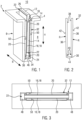
- the Figure 1 shows parts of a housing 2 of a not shown electrical heating device, which according to EP 1 872 986 A1 or according to 10 2019 216 481 A1 can be designed. Specifically shown is a partition wall 4 from which a heating device housing 6 protrudes, which projects from the partition wall 4 in the manner of a heating rib into a heating chamber identified by reference number 8 and is only open to a connection chamber 10.
- H denotes the height direction;
- B the width direction.
- the third direction in a Cartesian coordinate system is the thickness direction.
- a PTC element 14 is accommodated in a receiving pocket 12 formed by the heating device housing 6, on whose main side surfaces extending in the width and height directions contact plates 18 are accommodated as conductor tracks 16 and aluminum oxide plates are accommodated as insulating layers 20.
- the insulating layers 20 each cover a frame 22 in the height direction.
- FIG. 1 a lower cross member of the frame 22 is shown with reference number 24.
- Reference number 26 designates an upper cross member of the frame 22, which projects beyond the partition wall 4 in the direction of the connection chamber 10.
- the lower cross member 24 rests against a base 34 of the compensating element 32, which is formed by a web 30 of a compensating element 32.
- the compensating element 32 has opposing legs 36 which extend from the web 30.
- the legs 36 have flat, opposing inner surfaces 38. Between these inner surfaces 38 and the web 30, an outwardly projecting relief 40 is provided close to the base 34.
- the inner surfaces 38 of the legs 36 project inwards accordingly relative to this relief 40.
- the respective insulating layers 20 lie directly against these inner surfaces 38, wherein these insulating layers 20 each at least partially cover the lower cross member 24 and the upper cross member 26.
- the lower cross member 24 is T-shaped at its free end and forms a lower stop for the insulating layers 20, by means of which the insulating layers 20 are positioned on the underside relative to the frame 22.
- the outer surfaces of the legs 36 are convexly curved.
- the curvature has a radius of between 400 mm and 2000 mm, preferably between 600 mm and 1200 mm.
- Figure 2 also illustrates a positioning web 44 provided on the outside of the web 30. This positioning web 44 rests on a base 46 of the heating device housing 6.
- the frame 22 has longitudinal beams 48 which are thicker than the layering of the PTC element 14, the conductor tracks 16 and the insulating layer 20 but narrower than the distance between the outer surfaces 42 of the legs 36.
- the longitudinal beams 48 thus accommodate the compensating element 32 between them and position it relative to the frame 22.
- the width of the receiving pocket 12 is dimensionally adapted to the width of the frame 22 such that the frame 22 is accommodated in the receiving pocket 12 with little play in the width direction B.
- Reference numeral 50 designates opposing metallic inner surfaces of the heating device housing 6. The outer surfaces 42 of the legs 36 rest against these inner surfaces 50 under prestress.
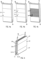
- FIGS. 4a to c illustrate conceivable designs for good heat-conducting contact, in particular in the form of a cold-welded connection between the compensating element 32 and the inner surfaces 50.
- Figure 4a illustrates a design according to Figure 2 with a single curvature 52, which has a uniform convex radius R of approximately 800 mm.
- the embodiment according to Figure 4c illustrates a knurled design on the outer surface 42 of the legs 36.
- This design has transversely extending grooves 54 which alternate with projections 56.
- the projections 56 can be deformed in the direction of the grooves 54 and into them.
- Figure 5 illustrates the free ends of the compensating element 32, which in this case end flush with the ends of the PTC element 14 in the width direction B.
- Figure 5 illustrates the arrangement of the PTC element 14 in a compensating element 32 according to Figure 4a
- connection lugs 58 which are electrically connected in the connection chamber 10, as is basically EP 10 2019, 216 481 A1 is known.
- the compensating element 32 is first fitted.
- a frame 22 provided with the PTC element 14 and the conductor tracks 16 is inserted between the legs 36 of the compensating element 32 together with the insulating layers 20 provided on both sides outside of the conductor tracks 16 until the lower cross member 24 abuts against the base 34 of the compensating element 32.
- the fitted compensation element 32 is inserted into the receiving pocket 12. This is done with the aid of a press-in tool, which acts against the upper cross member 26 and pushes the frame towards the bottom 46 of the heating device housing 6 via this cross member 26.
- the outer surfaces 42 of the legs 36 are usually deformed in the process. This results in a cold weld between the material of the compensation element 32 and the inner surfaces 50 of the heating device housing 6. The insertion movement ends when the positioning web 44 hits the bottom 46 of the heating device housing 6.
Landscapes
- Engineering & Computer Science (AREA)
- Physics & Mathematics (AREA)
- Thermal Sciences (AREA)
- Mechanical Engineering (AREA)
- Chemical & Material Sciences (AREA)
- Combustion & Propulsion (AREA)
- General Engineering & Computer Science (AREA)
- Resistance Heating (AREA)
- Air-Conditioning For Vehicles (AREA)
Applications Claiming Priority (1)
| Application Number | Priority Date | Filing Date | Title |
|---|---|---|---|
| DE102022134382.0A DE102022134382A1 (de) | 2022-12-21 | 2022-12-21 | Elektrische Heizvorrichtung |
Publications (2)
| Publication Number | Publication Date |
|---|---|
| EP4391720A2 true EP4391720A2 (fr) | 2024-06-26 |
| EP4391720A3 EP4391720A3 (fr) | 2024-07-31 |
Family
ID=89222315
Family Applications (1)
| Application Number | Title | Priority Date | Filing Date |
|---|---|---|---|
| EP23216152.1A Pending EP4391720A3 (fr) | 2022-12-21 | 2023-12-13 | Dispositif de chauffage électrique |
Country Status (3)
| Country | Link |
|---|---|
| EP (1) | EP4391720A3 (fr) |
| CN (1) | CN118234067A (fr) |
| DE (1) | DE102022134382A1 (fr) |
Citations (3)
| Publication number | Priority date | Publication date | Assignee | Title |
|---|---|---|---|---|
| EP1872986A1 (fr) | 2006-06-28 | 2008-01-02 | Catem GmbH & Co. KG | Chauffage électrique |
| EP3101365A1 (fr) | 2015-06-02 | 2016-12-07 | Eberspächer catem GmbH & Co. KG | Procédé de fabrication d'un dispositif de chauffage électrique |
| DE102019216481A1 (de) | 2019-10-25 | 2021-04-29 | Eberspächer Catem Gmbh & Co. Kg | Elektrische Heizvorrichtung |
Family Cites Families (4)
| Publication number | Priority date | Publication date | Assignee | Title |
|---|---|---|---|---|
| DE102019205848A1 (de) * | 2019-04-24 | 2020-10-29 | Eberspächer Catem Gmbh & Co. Kg | PTC-Heizelement und elektrische Heizvorrichtung mit einem solchen PTC-Heizelement und Verfahren zur Herstellung eines PTC-Heizelementes |
| US11105532B2 (en) * | 2019-08-01 | 2021-08-31 | Eberspächer Catem Gmbh & Co. Kg | Electric heating device and method for its manufacture |
| DE102019211567A1 (de) * | 2019-08-01 | 2021-02-04 | Eberspächer Catem Gmbh & Co. Kg | Elektrische Heizvorrichtung |
| DE102020201571A1 (de) * | 2020-02-10 | 2021-08-12 | Eberspächer Catem Gmbh & Co. Kg | Elektrische Heizvorrichtung und Verfahren zu deren Herstellung |
-
2022
- 2022-12-21 DE DE102022134382.0A patent/DE102022134382A1/de active Pending
-
2023
- 2023-12-13 EP EP23216152.1A patent/EP4391720A3/fr active Pending
- 2023-12-20 CN CN202311768789.0A patent/CN118234067A/zh active Pending
Patent Citations (3)
| Publication number | Priority date | Publication date | Assignee | Title |
|---|---|---|---|---|
| EP1872986A1 (fr) | 2006-06-28 | 2008-01-02 | Catem GmbH & Co. KG | Chauffage électrique |
| EP3101365A1 (fr) | 2015-06-02 | 2016-12-07 | Eberspächer catem GmbH & Co. KG | Procédé de fabrication d'un dispositif de chauffage électrique |
| DE102019216481A1 (de) | 2019-10-25 | 2021-04-29 | Eberspächer Catem Gmbh & Co. Kg | Elektrische Heizvorrichtung |
Also Published As
| Publication number | Publication date |
|---|---|
| EP4391720A3 (fr) | 2024-07-31 |
| DE102022134382A1 (de) | 2024-06-27 |
| CN118234067A (zh) | 2024-06-21 |
Similar Documents
| Publication | Publication Date | Title |
|---|---|---|
| EP3863373B1 (fr) | Dispositif de chauffage électrique et son procédé de fabrication | |
| EP3493650B1 (fr) | Dispositif de chauffage électrique | |
| EP1921896B1 (fr) | Elément produisant de la chaleur pour dispositif chauffant électrique et son procédé de fabrication | |
| EP2025541B1 (fr) | Elément d'un dispositif de chauffage produisant de la chaleur électrique | |
| EP2019268B1 (fr) | Chauffage électrique | |
| EP2337425A1 (fr) | Dispositif de chauffage électrique et élément produisant de la chaleur d'un dispositif de chauffage électrique | |
| EP1768458A1 (fr) | Elément chauffant d'un dispositif de chauffage | |
| DE102019216481A1 (de) | Elektrische Heizvorrichtung | |
| EP1916873A1 (fr) | Elément générateur de la chaleur pour un dispositif chauffant électrique et son procédé de fabrication | |
| EP4064788B1 (fr) | Dispositif de chauffage électrique | |
| DE102009033370A1 (de) | Stromschiene mit Kompensationsabschnitt | |
| EP3914799A1 (fr) | Agencement de profilés | |
| EP4391720A2 (fr) | Dispositif de chauffage électrique | |
| EP0938753B1 (fr) | Actionneur piezoelectrique pourvu d'une connexion electrique | |
| DE102013112732A1 (de) | Kraftfahrzeugbatterie zum rein elektrischen Antrieb eines Kraftfahrzeugs | |
| DE102019211565B4 (de) | Elektrische Heizvorrichtung und Verfahren zu deren Herstellung | |
| EP1467597B1 (fr) | Dispositif de chauffage | |
| EP4084577B1 (fr) | Dispositif de chauffage électrique et son procédé de fabrication | |
| DE102023115936A1 (de) | Elektrische Heizvorrichtung | |
| DE102020113402A1 (de) | Elektrische Heizvorrichtung | |
| WO2019072798A1 (fr) | Procédé de fabrication d'un chauffage pour réservoir et chauffage pour réservoir | |
| WO2014131619A1 (fr) | Empilement de piles à combustible | |
| DE102011112196B4 (de) | PTC-Heizung für eine hohe Spannung und einen hohen Strom | |
| EP2452408B1 (fr) | Barre omnibus modulaire | |
| DE102011017109B4 (de) | Heizeinrichtung |
Legal Events
| Date | Code | Title | Description |
|---|---|---|---|
| PUAI | Public reference made under article 153(3) epc to a published international application that has entered the european phase |
Free format text: ORIGINAL CODE: 0009012 |
|
| STAA | Information on the status of an ep patent application or granted ep patent |
Free format text: STATUS: THE APPLICATION HAS BEEN PUBLISHED |
|
| AK | Designated contracting states |
Kind code of ref document: A2 Designated state(s): AL AT BE BG CH CY CZ DE DK EE ES FI FR GB GR HR HU IE IS IT LI LT LU LV MC ME MK MT NL NO PL PT RO RS SE SI SK SM TR |
|
| PUAL | Search report despatched |
Free format text: ORIGINAL CODE: 0009013 |
|
| AK | Designated contracting states |
Kind code of ref document: A3 Designated state(s): AL AT BE BG CH CY CZ DE DK EE ES FI FR GB GR HR HU IE IS IT LI LT LU LV MC ME MK MT NL NO PL PT RO RS SE SI SK SM TR |
|
| RIC1 | Information provided on ipc code assigned before grant |
Ipc: F24H 9/02 20060101ALI20240625BHEP Ipc: H05B 3/44 20060101ALI20240625BHEP Ipc: F24H 9/1863 20220101ALI20240625BHEP Ipc: F24H 9/1818 20220101ALI20240625BHEP Ipc: F24H 1/12 20220101ALI20240625BHEP Ipc: F24H 3/04 20220101ALI20240625BHEP Ipc: B60H 1/22 20060101ALI20240625BHEP Ipc: H05B 3/50 20060101ALI20240625BHEP Ipc: H05B 3/06 20060101AFI20240625BHEP |
|
| STAA | Information on the status of an ep patent application or granted ep patent |
Free format text: STATUS: REQUEST FOR EXAMINATION WAS MADE |
|
| 17P | Request for examination filed |
Effective date: 20250107 |