EP4391737A1 - Module pour un appareil de commutation - Google Patents
Module pour un appareil de commutation Download PDFInfo
- Publication number
- EP4391737A1 EP4391737A1 EP22216518.5A EP22216518A EP4391737A1 EP 4391737 A1 EP4391737 A1 EP 4391737A1 EP 22216518 A EP22216518 A EP 22216518A EP 4391737 A1 EP4391737 A1 EP 4391737A1
- Authority
- EP
- European Patent Office
- Prior art keywords
- circuit board
- module
- sections
- rigid
- rigid circuit
- Prior art date
- Legal status (The legal status is an assumption and is not a legal conclusion. Google has not performed a legal analysis and makes no representation as to the accuracy of the status listed.)
- Granted
Links
Images




Classifications
-
- H—ELECTRICITY
- H05—ELECTRIC TECHNIQUES NOT OTHERWISE PROVIDED FOR
- H05K—PRINTED CIRCUITS; CASINGS OR CONSTRUCTIONAL DETAILS OF ELECTRIC APPARATUS; MANUFACTURE OF ASSEMBLAGES OF ELECTRICAL COMPONENTS
- H05K1/00—Printed circuits
- H05K1/02—Details
- H05K1/14—Structural association of two or more printed circuits
- H05K1/148—Arrangements of two or more hingeably connected rigid printed circuit boards, i.e. connected by flexible means
-
- H—ELECTRICITY
- H05—ELECTRIC TECHNIQUES NOT OTHERWISE PROVIDED FOR
- H05K—PRINTED CIRCUITS; CASINGS OR CONSTRUCTIONAL DETAILS OF ELECTRIC APPARATUS; MANUFACTURE OF ASSEMBLAGES OF ELECTRICAL COMPONENTS
- H05K7/00—Constructional details common to different types of electric apparatus
- H05K7/14—Mounting supporting structure in casing or on frame or rack
- H05K7/1417—Mounting supporting structure in casing or on frame or rack having securing means for mounting boards, plates or wiring boards
-
- H—ELECTRICITY
- H05—ELECTRIC TECHNIQUES NOT OTHERWISE PROVIDED FOR
- H05K—PRINTED CIRCUITS; CASINGS OR CONSTRUCTIONAL DETAILS OF ELECTRIC APPARATUS; MANUFACTURE OF ASSEMBLAGES OF ELECTRICAL COMPONENTS
- H05K7/00—Constructional details common to different types of electric apparatus
- H05K7/20—Modifications to facilitate cooling, ventilating, or heating
- H05K7/2039—Modifications to facilitate cooling, ventilating, or heating characterised by the heat transfer by conduction from the heat generating element to a dissipating body
- H05K7/20518—Unevenly distributed heat load, e.g. different sectors at different temperatures, localised cooling, hot spots
-
- H—ELECTRICITY
- H05—ELECTRIC TECHNIQUES NOT OTHERWISE PROVIDED FOR
- H05K—PRINTED CIRCUITS; CASINGS OR CONSTRUCTIONAL DETAILS OF ELECTRIC APPARATUS; MANUFACTURE OF ASSEMBLAGES OF ELECTRICAL COMPONENTS
- H05K2201/00—Indexing scheme relating to printed circuits covered by H05K1/00
- H05K2201/04—Assemblies of printed circuits
- H05K2201/047—Box-like arrangements of PCBs
-
- H—ELECTRICITY
- H05—ELECTRIC TECHNIQUES NOT OTHERWISE PROVIDED FOR
- H05K—PRINTED CIRCUITS; CASINGS OR CONSTRUCTIONAL DETAILS OF ELECTRIC APPARATUS; MANUFACTURE OF ASSEMBLAGES OF ELECTRICAL COMPONENTS
- H05K2201/00—Indexing scheme relating to printed circuits covered by H05K1/00
- H05K2201/09—Shape and layout
- H05K2201/09009—Substrate related
- H05K2201/09063—Holes or slots in insulating substrate not used for electrical connections
Definitions
- the invention relates to a module, in particular for arrangement in a switch cabinet of a low-voltage distributor or for use in combination with such a low-voltage distributor or a distribution box, wherein the module comprises a module housing.
- modules for arrangement in a control cabinet or for use in combination with a low-voltage distributor or a distribution box have already become known from the prior art, whereby such modules each have a module housing and can be designed, for example, as measuring modules for recording one or more measured variables in a low-voltage network.
- modules can be designed, for example, as a communication module, whereby a communication module is usually coupled to at least one measuring module in terms of signal technology, whereby the coupled measuring module has an interface for transferring recorded digital measurement data to the communication module, and whereby the communication module has a data memory for storing the digital measurement data and/or can also have, for example, a display for visualizing the measurement data.
- the electronic components required to operate such a module are usually arranged on two or more conventional, rigid circuit boards inside the module, whereby the two or more circuit boards are usually arranged one above the other in stacks for reasons of space.
- two conventional circuit boards are plugged together in two stacks using plug connections attached to them, so-called pin header connections.
- the disadvantage of this conventional design is that the plug connections or pin header connections between two or more conventional, rigid circuit boards are complex to manufacture and are also prone to errors in terms of signal transmission. As a result of mechanical and, in particular, thermal stresses that usually occur during handling and operation of such a module, soldering points for contacting the pin header connections on the respective circuit boards can be damaged, thus disrupting signal transmission between the two or more circuit boards connected by plug connections.
- PCB printed circuit board
- FR-4" or FR4 refers to a class of circuit board base material made of flame-retardant and flame-retardant composite materials, consisting of epoxy resin and glass fiber fabric.
- FR stands for for "flame retardant”.
- FR4 standard materials for circuit board production usually have a glass transition temperature TG of at least 135°C and are essentially rigid after lamination, i.e. after the curing process at elevated temperature and/or pressure.
- TG glass transition temperature
- the term "electronic component” can be understood to mean, for example, any active electronic component such as a chip, in particular a semiconductor chip, and/or any passive electronic component such as a capacitor, a resistor, an inductor or a magnetic element, for example a ferrite core element.
- Other examples of electronic components that can be embedded in or positioned on a circuit board are data memories such as dynamic random access memory (DRAM), filters that can be configured, for example, as high-pass filters, low-pass filters or band filters, or that can be used as frequency filters.
- DRAM dynamic random access memory
- An integrated circuit such as a so-called logic IC, any signal processing component such as a microprocessor, any power management component, any optoelectronic device, any voltage converter such as a DC/DC converter or AC/DC converter, any electromechanical converter such as a lead zirconium titanate (PZT) sensor and/or actuator, as well as any transmitting unit or receiving unit for electromagnetic waves such as an RFID chip or transponder, any cryptographic component, capacitance, inductance or switch such as a transistor-based switch alone or in combination with the aforementioned or together with other functional electronic components is also included in the aforementioned term of an electronic component.
- IC integrated circuit
- any signal processing component such as a microprocessor
- any power management component any optoelectronic device
- any voltage converter such as a DC/DC converter or AC/DC converter
- any electromechanical converter such as a lead zirconium titanate (PZT) sensor and/or actuator
- any transmitting unit or receiving unit for electromagnetic waves such as an RFID chip or
- an electronic component can also include a microelectromechanical system (MEMS for short), a battery, an accumulator, a power supply, a camera or an antenna.
- MEMS microelectromechanical system
- other electronic components can also be embedded in a circuit board.
- a magnetic element can be used as an electronic component.
- Such a magnetic Element may be a permanent magnetic element, such as a ferromagnetic element, an antiferromagnetic element or a ferrimagnetic element, for example a ferrite core, or may be a paramagnetic element.
- Such an electronic component may be surface-mounted on a circuit board and/or embedded in its interior.
- a sectionally flexible circuit board assembly with at least three rigid circuit board sections and with at least two flexible circuit board sections is arranged within the module housing, wherein at least one flexible circuit board section is arranged between two adjacent rigid circuit board sections and is electrically connected to these two adjacent rigid circuit board sections in a signal-conducting manner, wherein the sectionally flexible circuit board assembly forms a three-dimensional structure in the installed position within the module housing, in which at least a first pair of two adjacent rigid circuit board sections has a first angle and at least a second pair of two adjacent rigid circuit board sections encloses a second angle with each other.
- a sectionally flexible circuit board assembly with at least three rigid circuit board sections and with at least two flexible circuit board sections, each of which is arranged between two adjacent rigid circuit board sections, can advantageously increase the total rigid circuit board area available for mounting electronic components.
- the mounting density i.e. the number of electronic components per circuit board area, can thus advantageously be reduced.
- temperature-sensitive electronic components or those electronic components that are required for particularly temperature-sensitive measurements can be arranged on a first rigid circuit board section, while other electronic components that heat up during operation of the module and thus produce waste heat, as is the case with a power supply, for example, are arranged on a second or further rigid circuit board section that is further away from the first rigid circuit board section.
- the partially flexible circuit board assembly is arranged in the installation position within the module housing in such a way that the circuit board assembly forms a three-dimensional structure in which at least two pairs of two adjacent rigid circuit board sections each enclose an angle with each other.
- the circuit board assembly according to the invention therefore forms a three-dimensional structure in which a first pair of two adjacent rigid circuit board sections enclose a first angle with each other and a second pair of two adjacent circuit board sections enclose a second angle with each other.
- the first angle and the second angle can be the same size or different sizes.
- Any additional rigid circuit board sections that may be present can in turn enclose a third or further angle in pairs adjacent to one another.
- Such a third or further angle between a third or further pair of two adjacent rigid circuit board sections can in turn be the same size or different sizes in relation to the first and/or the second angle.
- the rigid circuit board sections which are adjacent in pairs, are each connected to one another in a movable or articulated manner by at least one flexible circuit board section arranged therebetween.
- the spatial or three-dimensional structure of the circuit board assembly according to the invention in the installation position within the module housing offers the advantage that at least two pairs of two adjacent rigid circuit board sections are not arranged parallel, but rather at an angle to one another. This allows the spatial distance between electronic components positioned on the circuit board assembly to be advantageously increased. Negative influences due to undesirable heat conduction and/or heat radiation between individual electronic components can be largely reduced by suitable positioning on the circuit board assembly at a spatial distance between the relevant electronic components. In particular, negative influences on a temperature measurement due to undesirable waste heat development during operation of a module can be avoided by the spatial structure according to the invention in the installation position of the circuit board assembly within the module.
- Such a module according to the invention is suitable for arrangement in a control cabinet of a low-voltage distributor or for use in combination with such a low-voltage distributor or a distribution box, its use is not limited to the aforementioned arrangements.
- Such a printed circuit board assembly can be adapted to an individual module housing of a module in a particularly flexible and efficient manner if, in a module according to the invention, two adjacent rigid printed circuit board sections form an angle to one another in a range from 10° to 170°, preferably in a range from 30° to 150°, particularly preferably in a range from 60° to 120°.
- a circuit board assembly can be flexibly adapted to the respective housing geometry within a module housing, so that on the one hand the available interior space of the module housing is used as best as possible by the spatial, three-dimensional structure of the circuit board assembly, and on the other hand electronic components that heat up during operation of the module and thus produce waste heat, as is the case with a power supply, for example, can be arranged on a rigid circuit board section spatially separated or further away from heat-sensitive electronic components that are positioned on other rigid circuit board sections.
- the angles between two adjacent rigid circuit board sections of the circuit board assembly are each of the same size.
- the rigid circuit board sections which are comprised by the partially flexible circuit board assembly can each be arranged substantially at right angles, i.e. at an angle of substantially 90°, in relation to a respective adjacent rigid circuit board section.
- the flexible circuit board sections arranged between two adjacent rigid circuit board sections, which serve for the signal-conducting, electrical connection of the respective adjacent rigid circuit board sections, are in such a case For example, each one is bent in a bending radius with a bending angle of about 90° and is therefore the same size.
- angles between two adjacent rigid circuit board sections are each of different sizes and/or are different sizes in groups.
- This spatial arrangement according to the invention of a sectionally flexible circuit board assembly in the installation position in the interior of the module housing offers the advantage of being able to be adapted particularly flexibly to individual geometries of different module housings.
- niches or projections in a module housing can be used to accommodate corresponding circuit board sections of the circuit board assembly.
- the selection of the angle(s) between two adjacent rigid circuit board sections in the installation position can also be adapted to the respective geometric framework conditions of different module housings.
- a module housing that deviates from a symmetrical cuboid or cube shape and that has, for example, notches, niches, projections and/or contour sections in the form of a polyhedron or a rotational body, it can be expedient if the angles between pairs of adjacent rigid circuit board sections in the installation position of the three-dimensional structure of the circuit board assembly in the interior of the module housing are each of different sizes or are different sizes in groups.
- each rigid circuit board section in the installed position within the module housing forms one, preferably its own, level of the three-dimensional structure.
- the available interior space of the module housing can be used as well as possible in order to arrange the partially flexible circuit board assembly in the installed position within the module housing as a three-dimensional structure with the largest possible spacing between the individual rigid circuit board sections.
- this Design variant which advantageously increases the area of the circuit board assembly that can be equipped with electronic components.
- the individual rigid circuit board sections can, for example, be arranged at least partially or in sections along the inner walls of the module housing. It can be particularly useful if the individual rigid circuit board sections are attached to the inner walls of the module housing at least in sections. In this embodiment, all pairs of two adjacent rigid circuit board sections form an angle with each other.
- a particularly robust three-dimensional structure of a printed circuit board assembly can be arranged if at least two rigid printed circuit board sections can be connected to one another in the installed position within the module housing with a detachable positive connection.
- two or more rigid circuit board sections can be connected directly to one another in the installation position in order to fix the respective circuit board assembly in a three-dimensional structure that is as robust as possible.
- mechanical spacers can be arranged between two rigid circuit board sections or connected to them in a form-fitting and/or material-fitting manner in order to connect individual rigid circuit board sections to one another.
- SMD spacers SMD, short for "Surface Mount Device”
- SMD Surface Mount Device
- the detachable positive connection is selected from the group comprising, preferably consisting of: snap-in connection, plug-in connection, tongue and groove connection, tongue and groove connection, key connection, zipper connection, Velcro connection.
- edges of two rigid circuit board sections that form an angle with each other and touch each other can have complementary projections or recesses in the form of a tongue and groove joint, whereby protruding springs or prong-shaped elements that are machined onto the edge of one of the two rigid circuit board sections to be connected can be inserted into corresponding grooves in the other rigid circuit board section.
- a tongue and groove joint can be designed, for example, in the form of one or more dovetail joints or zinc plated joints.
- the positive plug or snap connections of two rigid circuit board sections can be additionally soldered after the mechanical or positive joining. This ensures that the plugged-together circuit board assembly in the installation position remains in shape even under mechanical stress, for example in the event of vibrations, and the plugged-together rigid circuit board sections are also firmly connected to one another by means of the soldering points.
- corresponding soldering surfaces and corresponding electrical vias can be provided, for example, on the edges of two rigid circuit board sections to be connected. After the mechanical or positive joining of the touching rigid circuit board sections, the corresponding soldering surfaces and/or vias can then be soldered in order to create corresponding electrical contact lines between the two connected rigid circuit board sections.
- two adjacent rigid circuit board sections that form an angle to each other and touch each other can can also be designed as a snap-in connection, plug-in connection, keyway connection, zipper connection and/or Velcro connection.
- circuit board assembly is selected from the group comprising, preferably consisting of: rigid-flexible circuit board assembly, semi-flexible circuit board assembly, flexible circuit board assembly glued to aluminum plates.
- rigid-flex circuit boards are already known, which are obtained by pressing a combination of flexible and rigid layers.
- flexible polyimide films are located on or between conventional FR4 layers, whereby after appropriate deep milling, areas with different thicknesses and different flexibility of such a rigid-flex circuit board are obtained.
- Rigid-flex circuit boards are also referred to as "rigid-flex circuit boards".
- Such a rigid-flex circuit board assembly is particularly flexible in its handling, since the flexible circuit board sections made of flexible polyimide films can also be dynamically deformed if necessary, for example bent, twisted or folded.
- circuit board Another alternative to conventional, rigid circuit boards is the so-called semi-flexible circuit board.
- a layer stack of a circuit board made up of several fiber layers can be tapered down to just a few layers by milling or by punching out recessed areas.
- the individual fiber layers pre-impregnated with reactive resins are also known as prepregs.
- a standard thin laminate FR4 material is used to provide a cost-effective alternative to rigid-flex circuit boards.
- the tapered circuit board area is typically provided with a permanently flexible lacquer layer and can then be bent a few times.
- Such a semi-flexible circuit board assembly can be used as a cost-effective "flex-to-install" solution, in which the desired spatial structure of the circuit board assembly is formed once by bending and/or folding the rigid circuit board sections accordingly and then inserted into the module housing of the corresponding module.
- Such semi-flexible circuit board assemblies that are made from rigid circuit boards made of FR4 material and thin laminate sections that are flexible to a limited extent in between can also be used as a section-by-section flexible circuit board assembly within the scope of the invention.
- flexible circuit boards are also used in the form of, for example, thin flexible circuit boards or conductor foils based on polyimide foils, which are glued to one or more aluminum heat sinks. Assemblies built with these are more expensive, but can be folded to save space in tight spaces.
- circuit board assemblies can be provided that have particularly good heat dissipation properties and are suitable for assembly with are particularly suitable for temperature-sensitive electronic components.
- a particularly long-lasting and precisely functioning module can be provided according to the invention if temperature-sensitive electronic components are arranged on the sectionally flexible printed circuit board assembly in the installation position of the three-dimensional structure at a spatial distance from heat-generating electronic components.
- the temperature-sensitive electronic components can be arranged in the installation position of the three-dimensional structure of the sectionally flexible printed circuit board assembly within the module housing at as great a distance as possible from heat-generating electronic components in the interior of the module housing in order to avoid as far as possible undesirable influences due to thermal radiation or thermal conduction between the electronic components in the interior of the module housing or the printed circuit board assembly.
- a space-saving module in which at least two equally sized rigid circuit board sections are formed, which are arranged opposite one another in the installation position of the partially flexible circuit board assembly within the module housing.
- This design can, for example, be used in a particularly space-saving manner in cuboid or cube-shaped module housings, i.e. in module housings that are at least partially symmetrically shaped.
- At least one rigid circuit board section of the circuit board assembly is equipped with electronic components on both sides on two outer sides facing away from one another.
- two or more or all of the rigid Circuit board sections of the circuit board assembly arranged within the module housing are each populated on both sides.
- electronic components can also be embedded within one or more rigid circuit board sections, i.e. cast within the FR4 layer structure of the respective circuit board section using a lamination process under pressure and temperature exposure.
- a module according to the invention can be used in a particularly diverse manner if the module is a measuring module for a switching device, in particular for a load-break switch, for measuring at least one measured variable in a low-voltage network, and/or a communication module.
- measuring module refers here to a module for measuring at least one measured variable in a low-voltage network, wherein the measuring module comprises a module housing, at least one phase contact for connection to a respective outer conductor and at least one measuring sensor for detecting at least one measured variable attributable to the respective outer conductor, and wherein at least one function indicator is advantageously provided for each phase contact, wherein the respective at least one function indicator is arranged on the module housing, and wherein the measuring module is designed to control the respective at least one function indicator depending on the at least one measured variable detected.
- such a measuring module or several measuring modules can interact with a load-break switch in a measuring system, wherein the load-break switch usually has a switch housing, at least one phase terminal for connection to a respective external conductor and at least one switch terminal for connection to a respective continuing line and is designed to selectively switch an electrical connection between the at least one phase terminal and the at least one switch terminal on or off.
- the at least one phase contact of the measuring module can be complementary to the at least one phase terminal and/or to the at least one switch terminal of the load-break switch. be shaped so that it can be clamped into at least one phase terminal or switch terminal of the load-break switch.
- the term "communication module” refers here to a module which is coupled to at least one measuring module in terms of signal technology by means of a communication channel, in particular a wireless one, wherein the at least one measuring module has an interface for transferring digital measurement data acquired by at least one measuring sensor to the communication module, and wherein the communication module has a data memory for storing the digital measurement data.
- the interface of the at least one measuring module can also serve as a data interface for an external mobile device.
- the measuring module is equipped with a radio interface, for example a Bluetooth or ZigBee-compatible radio interface
- communication or data transmission between the measuring module and an external mobile device can take place using radio signals, for example via Bluetooth, provided that the device used is equipped with suitable software.
- the communication module can be conveniently equipped as a gateway.
- a web server can also be implemented.
- a user can then, for example, read out details of the recorded digital measurement data from a mobile device via a web browser access and check the device parameters of the measuring module and change or parameterize them if necessary.
- the communication module can have one or more data interfaces, for example for an external mobile terminal and/or for stationary terminals, desktop computers, network computers and the like, with which a user can, for example, can read the digital measurement data stored in the data memory of the communication module via a web browser access from a mobile device or a network computer and/or can read details of the recorded digital measurement data via the communication channel and can check the device parameters of the measuring module and change or parameterize them if necessary.
- data interfaces for example for an external mobile terminal and/or for stationary terminals, desktop computers, network computers and the like, with which a user can, for example, can read the digital measurement data stored in the data memory of the communication module via a web browser access from a mobile device or a network computer and/or can read details of the recorded digital measurement data via the communication channel and can check the device parameters of the measuring module and change or parameterize them if necessary.
- the communication module can, for example, also have a display for visualizing the measurement data.
- the communication module comprises a mobile device, preferably a smartphone and/or a notebook computer, or is a mobile device.
- the measuring module and the communication module are integrated in a compact design in a common module housing.
- the measuring module and the communication module usually communicate with each other in close proximity using signals, since the individual modules are mounted in the same control cabinet of a low-voltage distributor, for example. If the measuring module and the communication module are integrated in a common module housing, a wired communication channel for data transfer can be implemented instead of a wireless communication channel for data transfer between the individual module units. For example, corresponding complementary or corresponding plug/socket connections in the connectable or pluggable housings can be used to create a wired communication channel.
- the individual different module units can be arranged on rigid circuit board sections of a circuit board assembly and connected to one another in a fail-safe manner with flexible circuit board sections in between.
- a module according to the invention can be attached particularly easily to a mounting rail in a control cabinet if the module housing is designed as a mounting rail housing, preferably as a top-hat rail housing.
- a switch cabinet is also specified, in particular a switch cabinet of a low-voltage distributor, wherein at least one module according to the invention according to one of claims 1 to 13 is arranged in the switch cabinet.
- Fig.1 shows a module 1 according to the invention with a module housing 2 and an interior 3.
- the module housing 2 is shown closed here, which is why the interior 3 and the corresponding inner walls of the module housing 2 in this view cannot be viewed.
- Fig.8 A comparable module 1 with a module housing 2 with the housing cover removed is illustrated.
- Fig.2 shows a conventional double-decker circuit board 5 known from the prior art with a conventional plug connection in the form of a pin strip connection 6.
- Two conventional circuit boards 5 are arranged one above the other in layers for reasons of space and plugged together in double layers with pin strip connections 6 attached to them.
- Electronic conductor tracks of the first circuit board 7 are electrically connected to electronic conductor tracks of the second circuit board 8 in a signal-conducting manner by means of the mechanical plugs of the pin strip connections 6.
- the disadvantage of this conventional design is that the plug connections or pin strip connections 6 between two or more conventional, rigid circuit boards 7, 8 are complex to manufacture and are also prone to errors in terms of signal transmission.
- soldering points for contacting the pin strip connections 6 on the respective circuit boards 5, 7, 8 can be damaged and the signal transmission between the two or more circuit boards 5, 7, 8 connected by plug connections can be disrupted.
- FIG.2 Another disadvantage of using a Fig.2 shown conventional double-deck circuit board 5 in connection with a generic module, that the electronic components or electronic parts 10 attached to it are usually positioned close to one another.
- heat-generating electronic components 11, which become hot during operation and produce waste heat, such as one or more power supplies 12, are located on the same circuit board 7, 8 or at least in spatial proximity with other electronic components 10 or electronic components such as microcontrollers or semiconductor chips 13, i.e. with temperature-sensitive electronic components 14, which is disadvantageous.
- Electronic components 11, 12 of such a module which heat up considerably during operation and give off waste heat, have negative effects on the temperature-sensitive components required, for example, for precise temperature measurement.
- electronic components 13,14 conductor tracks and/or individual layers of a circuit board 5. Due to the undesirable heat conduction and/or heat radiation of the heat-generating electronic components 11,12, an exact temperature measurement is negatively influenced or disturbed.
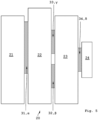
- Fig.3 shows a plan view of a first, partially flexible circuit board assembly 20 according to the invention, as is intended for use in a module housing of a generic module.
- a first rigid circuit board section 21, a second rigid circuit board section 22, a third rigid circuit board section 23 and a fourth rigid circuit board section 24 are each electrically connected to one another in a signal-conducting manner by means of intermediate flexible circuit board sections 31, 32, 33.
- the first flexible circuit board section 31 connects the first rigid circuit board section 21 and the second rigid circuit board section 22 to one another.
- the second flexible circuit board section 32 connects the second rigid circuit board section 22 and the third rigid circuit board section 23 to one another.
- the third flexible circuit board section 33 connects the third rigid circuit board section 23 and the fourth rigid circuit board section 24 to one another.
- the rigid circuit board sections 21, 22, 23, 24 of the circuit board assembly 20 which are shown flat in a plane in the top view, can be folded or plugged together to form a three-dimensional, spatial structure in the installation position within a module housing (not shown here) in order to be able to make the best possible use of the available interior space within the corresponding module housing.
- the flexible circuit board sections 31, 32, 33 are made here, for example, from a flexible polyimide film material and enable the formation of a particularly flexible, three-dimensional structure of the circuit board assembly 20 in the installation position within the module housing, whereby two adjacent rigid circuit board sections 21, 22, 23, 24 can enclose the same or different angles ⁇ , ⁇ , ⁇ with respect to one another, for example in a range from 10° to 170°.
- the first flexible circuit board section 31 can be bent or folded at a first angle ⁇ , the second flexible circuit board section 32 at a second angle ⁇ , and the third flexible circuit board section 33 at a third angle ⁇ in order to enable a spatial three-dimensional structure of the rigid circuit board sections 21,22,23,24 of the circuit board assembly 20.
- the sections of the printed circuit board assembly 20 are each shown flat in one plane. The angles ⁇ , ⁇ and ⁇ between the pairs of adjacent rigid printed circuit board sections 21,22; 22,23 and 23,24 are thus each 180°.
- the multiple, or here four, rigid circuit board sections 21, 22, 23, 24 that are connected to one another in a signal-conducting manner increase the available circuit board surface for equipping electronic components.
- a circuit board assembly 20 according to the invention offers a particularly advantageous possibility of spatially separating or deconvoluting heat-generating electronic components from temperature-sensitive electronic components, which are required for high-precision temperature measurements, as far as possible in their positions on the circuit board assembly 20.
- Undesirable impairments due to heat conduction and/or heat radiation between the heat-generating electronic components and those temperature-sensitive electronic components that should not get hot can be advantageously avoided during operation of a generic module that is equipped with such a circuit board assembly 20.
- Fig.4 shows a second circuit board assembly 20 according to the invention in a plan view from above.
- a total of six rigid circuit board sections 21, 22, 23, 24, 25, 26 are electrically connected to one another in a signal-conducting manner by means of a total of five flexible circuit board sections 31, 32, 33, 34, 35 located between them.
- the arrangement of the six rigid circuit board sections 21, 22, 23, 24, 25, 26 shown here corresponds to a cuboid network and can be particularly useful in a shown, cuboid module housing of a module according to the invention.
- the flexible circuit board sections 31, 32, 33, 34, 45 are made here, for example, from a flexible polyimide film material and enable the formation of a particularly flexible, three-dimensional structure of the circuit board assembly 20 in the installation position within a module housing, whereby two adjacent rigid circuit board sections 21, 22, 23, 24, 25, 26 can each enclose an angle ⁇ , ⁇ , ⁇ , ⁇ with each other, for example in a range of 10° to 170°.
- the angles ⁇ , ⁇ , ⁇ , ⁇ , ⁇ can each be the same size or different sizes.
- angles ⁇ , ⁇ , ⁇ , ⁇ , ⁇ between the adjacent rigid circuit board sections 21, 22, 23, 24, 25, 26 in the installation position are expediently selected to be substantially the same size, in particular each amounting to 90°.
- the rigid circuit board sections 21, 22, 23, 24, 25, 26 of the circuit board assembly 20, shown here flat in a plan view, can be folded or plugged together in the installation position within a preferably cuboid-shaped module housing (not shown here) to form a three-dimensional, spatial cuboid-shaped structure in order to be able to make the best possible use of the available interior space within such a module housing.
- the six rigid circuit board sections 21, 22, 23, 24, 25, 26 connected to one another in a signal-conducting manner here further increase the available circuit board area for equipping with electronic components.
- Fig.5 shows a view from above of a third printed circuit board assembly 20 according to the invention with a total of four interconnected rigid printed circuit board sections 21,22,23,24.
- two flexible circuit board sections are provided, namely a second 32 and a third 33 flexible circuit board section, each of which second rigid circuit board section 22 and the third rigid circuit board section 23 are electrically connected to one another in a signal-conducting manner.
- this circuit board assembly 20 can be spatially structured such that the second rigid circuit board section 22 and the third rigid circuit board section 23 form an angle with one another.
- the second flexible circuit board section 32 and the third flexible circuit board section 33 are each folded or bent by the same angle with respect to one another.
- the second angle ⁇ of the second flexible circuit board section 32 and the third angle ⁇ of the third flexible circuit board section 33 are therefore the same size in this case in the spatially structured installation position of the circuit board assembly 20.
- Fig.6 shows an isometric view obliquely from the side of a fourth printed circuit board assembly 20 according to the invention, which is folded as a three-dimensional spatial structure 40.
- the printed circuit board assembly 20 shown here comprises four rigid printed circuit board sections 21, 22, 23, 24 and three flexible printed circuit board sections 31, 32, 33, wherein a first flexible printed circuit board section 31 is arranged between the first 21 and the second 22 rigid printed circuit board section, a second flexible printed circuit board section 32 is arranged between the second 22 and the third 23 rigid printed circuit board section, and a third flexible printed circuit board section 33 is arranged between the third 23 and the fourth 24 rigid printed circuit board section.
- the flexible printed circuit board sections 31, 32, 33 each serve for the signal-conducting electrical connection of the adjacent rigid printed circuit board sections 21, 22, 23, 24.
- the flexible circuit board sections 31, 32, 33 are designed here, for example, as polyimide flexible circuit boards, i.e. as flexible polyimide film carriers with conductor tracks arranged on them.
- the rigid circuit board sections 21, 22, 23, 24 are manufactured here, for example, as multi-layer laminated PCB circuit boards made of FR4 material.
- the printed circuit board assembly 20 is in Fig.6 already folded as a three-dimensional structure 40, whereby the rigid Circuit board sections 21, 22, 23, 24 each enclose an angle with one another in pairs.
- the first rigid circuit board section 21 and the second rigid circuit board section 22 enclose a first angle ⁇ with one another.
- the second rigid circuit board section 22 and the third rigid circuit board section 23 enclose a second angle ⁇ with one another.
- the third rigid circuit board section 23 and the fourth rigid circuit board section 24 enclose a third angle ⁇ with one another.
- the first angle ⁇ , the second angle ⁇ and the third angle ⁇ between the respectively adjacent rigid circuit board sections 21, 22, 23 correspond in the installed position of the three-dimensional structure 40 to the bending angle of the flexible circuit board sections 31, 32, 33 located between them.
- the fourth rigid circuit board section 24 forms a fourth angle 5 with the first rigid circuit board section 21.
- the two rigid circuit board sections 21 and 24 are plugged together at their edges with a positive connection in the form of a tongue and groove with several locking lugs 50 and complementary locking grooves 51 into which the locking lugs 50 engage.
- the plugged together locking lugs 50 or locking grooves 51 are also connected to one another in a materially bonded manner by means of soldered connections.
- soldered connections can be arranged in such a way that they not only prevent the plug connection of the rigid circuit board sections 21, 24 from being opened accidentally, but also that signal-conducting electrical connections are achieved between the two rigid circuit board sections 21, 24 that are plugged together.
- corresponding conductor tracks or contacts can be soldered to one another at the edges of the rigid circuit board sections 21, 24 that touch one another.
- Each rigid circuit board section 21,22,23,24 of the three-dimensional structure 40 forms a separate plane 41,42,43,44 in the assembled installation position.
- the first rigid circuit board section 21 forms Fig.6 a first, front plane 41 of the spatial structure 40 shown.
- the second rigid circuit board section 22 forms a second, lower plane 42 of the spatial structure 40 shown.
- the third rigid circuit board section 23 forms a third, rear plane 43 of the spatial structure 40 shown.
- the fourth rigid circuit board section 24 forms a fourth, upper plane 44 of the spatial structure 40 shown.
- the rigid circuit board sections 21, 22, 23, 24 or the planes 41, 42, 43, 44 formed thereby are each essentially perpendicular to one another.
- the angles ⁇ , ⁇ , ⁇ , ⁇ are each approximately 90°.
- the upper rigid circuit board section 24 and the lower rigid circuit board section 22 each have three congruent recesses 60 for current measuring sensors.
- Current measuring sensors or current transformers are electrical components with which the current intensity in cables and busbars can be measured galvanically isolated - and thus contactlessly - based on the magnetic flux density triggered by electrical currents.
- the Fig.6 For a better overview, the printed circuit board assembly 20 illustrated is shown before the electronic components are fitted.
- Fig.7 shows the Fig.6 illustrated circuit board assembly 20 after assembly with electronic components 10. Due to the large assembly area that the circuit board assembly 20 offers, heat-generating electronic components 11 such as one or more power supplies 12 of microcontrollers, semiconductor chips 13 and/or other temperature-sensitive electronic components 14 can be spatially separated during operation. The total available assembly area of the circuit board assembly 20 can be increased even further if at least one rigid circuit board section 23 is equipped with electronic components 10 on both sides, i.e. on its first outer side 211 and on its opposite second outer side 212.
- heat-generating electronic components 11 such as one or more power supplies 12 of microcontrollers, semiconductor chips 13 and/or other temperature-sensitive electronic components 14 can be spatially separated during operation.
- the total available assembly area of the circuit board assembly 20 can be increased even further if at least one rigid circuit board section 23 is equipped with electronic components 10 on both sides, i.e. on its first outer side 211 and on its opposite second outer side 212.
- Fig.6 As mentioned earlier Fig.6 described are in Fig.7 the two rigid circuit board sections 21 and 24 are plugged together at their edges with a positive connection in the form of a bung with several locking lugs 50 and complementary locking grooves 51 into which the locking lugs 50 engage.
- corresponding conductor tracks or contacts are soldered to one another, for example, on the edges of the rigid circuit board sections 21, 24 that touch one another.
- a housing of a current measuring sensor 61 is sketched, which is arranged in the area of the recess 60.
- Several measuring sensors are provided on the circuit board assembly 20, for example three identical current measuring sensors 61 are provided, each of which is arranged in the area of the three recesses 60.
- the current measuring sensors 61 are used to detect the current intensity in a respective outer conductor of a power line.
- Fig.8 shows in an exploded view the Fig.6 shown, folded into a three-dimensional structure 40, before being fitted with electronic components and before being inserted into an interior 3 of a module housing 2 of a module 1 according to the invention.
- the module 1 here is a measuring module 100.
- the three-dimensional structure 40 of the circuit board assembly 20 borders as closely as possible to the inner walls 4 of the module housing 2, whereby the available interior 3 of the module housing 2 is used as best as possible.
- the module housing 2 can be sealed after the circuit board assembly 20 has been inserted with a Fig.8
- the housing cover (not shown) can be closed by pressing the Fig.1 referred to.
- Fig.9 illustrated - comparable to Fig.8 - in an exploded view the Fig.7 shown, already equipped with electronic components 10,11,12,13,14 Printed circuit board assembly 20 before insertion into an interior 3 of a module housing 2 of a module 1 according to the invention.
- the module 1 is a measuring module 100, which is equipped with three current measuring sensors 61, in particular for current measurement.
- Fig.10 shows an exploded view of a fifth circuit board assembly 20 according to the invention, which is folded as a three-dimensional spatial structure 40, before being inserted into an interior 3 of a module housing 2 of a module 1 according to the invention.
- This module 1 is, for example, a communication module 101.
- the circuit board assembly 20 shown here comprises a total of five rigid circuit board sections 21, 22, 23, 24, 25, which are each electrically connected to one another in a signal-conducting manner with pairs of flexible circuit board sections 31, 32, 33, 34 lying between them.
- the rigid circuit board sections 21, 23 and 25 are each arranged essentially parallel to one another and form a first level 41, a third level 43 and a fifth level 45 of the spatial structure 40 of the circuit board assembly 20.
- the first, third and fifth rigid circuit board sections 21, 23, 25 each enclose an angle of approximately 90° with the underlying second rigid circuit board section 22 or with a second level 42 of the structure 40 formed by this second rigid circuit board section 22.
- the fifth rigid circuit board section 45 is here electrically connected to the third circuit board section 43 in a signal-conducting manner by means of an intermediate fourth rigid circuit board section 24 and by means of two flexible circuit board sections 33, 34.
- the fourth rigid circuit board section 24 here forms a fourth level 44 of the structure 40, which is arranged essentially parallel to the second level 42 or to the second rigid circuit board section 22.
- the angle between each two adjacent rigid circuit board sections 21, 22, 23, 24, 25 is essentially 90°.
- the rigid circuit board sections 21, 23, 24, 25 are mechanically connected to one another by means of spacers 49.
- the rigid circuit board sections in particular the centrally arranged fifth rigid circuit board section 25, can be equipped with electronic components on both sides on the respective opposite outer sides 211, 212.
- the circuit board assembly 20 thus provides a very large circuit board surface for assembly and, due to the spatial structure 40, also offers sufficient space to spatially separate electronic components that generate heat during operation from temperature-sensitive electronic components.
- the Fig.10 For the sake of clarity, the printed circuit board assembly 20 shown is not yet equipped with electronic components.
- the fourth rigid circuit board section 24 may also be missing or, together with the adjacent flexible circuit board sections 33, 34, may form part of a continuous, one-piece flexible circuit board section between the rigid circuit board sections 23 and 25.
- Fig. 11 shows in a detailed view the top of the Fig.6 shown printed circuit board assembly 20 according to the invention with a positive and electrically conductive connection of two rigid printed circuit board sections 21,24 for fixing the installation position of the printed circuit board assembly as a three-dimensional structure 40.
- Fig. 12 shows the Fig. 11 illustrated circuit board assembly 20 in an isometric view obliquely from the side.
- the circuit board assembly 20 is shown without electronic components.
- the two rigid circuit board sections 21 and 24 are plugged together at their edges with a positive connection in the form of a tongue with several locking lugs 50 and complementary locking grooves 51 into which the locking lugs 50 engage.
- corresponding conductor tracks or contacts are soldered to soldering surfaces 52 or soldering pads 52 on the edges of the rigid printed circuit board sections 21, 24 that touch one another. The soldering points also stabilize the printed circuit board assembly 20 in its installation position and prevent the plugged together rigid printed circuit board sections 21, 24 from being accidentally opened.
- Corresponding through-holes 53 so-called vias 53, which are arranged directly adjacent to the soldering surfaces 52 or soldering pads 52, are used here, due to the multi-layer structure of the printed circuit board sections 21, 24, to connect corresponding conductor tracks to one another layer by layer in a correct electrical signal-conducting manner at the corresponding soldering points 54.
- the through-platings or vias 53 can also be designed as "half" vias 53 on the edges of the corresponding rigid circuit board sections 21, 24, i.e. as vias 53 that are half open in the longitudinal direction of the through-platings 53.
- the soldering points 54 which cover the soldering surfaces 52 and the vias 53 with solder after soldering, are only indicated by dashed lines.
Landscapes
- Engineering & Computer Science (AREA)
- Microelectronics & Electronic Packaging (AREA)
- Physics & Mathematics (AREA)
- Thermal Sciences (AREA)
- Combinations Of Printed Boards (AREA)
- Mounting Of Printed Circuit Boards And The Like (AREA)
Priority Applications (1)
| Application Number | Priority Date | Filing Date | Title |
|---|---|---|---|
| EP22216518.5A EP4391737B1 (fr) | 2022-12-23 | 2022-12-23 | Module pour un appareil de commutation |
Applications Claiming Priority (1)
| Application Number | Priority Date | Filing Date | Title |
|---|---|---|---|
| EP22216518.5A EP4391737B1 (fr) | 2022-12-23 | 2022-12-23 | Module pour un appareil de commutation |
Publications (3)
| Publication Number | Publication Date |
|---|---|
| EP4391737A1 true EP4391737A1 (fr) | 2024-06-26 |
| EP4391737B1 EP4391737B1 (fr) | 2026-01-28 |
| EP4391737C0 EP4391737C0 (fr) | 2026-01-28 |
Family
ID=84602703
Family Applications (1)
| Application Number | Title | Priority Date | Filing Date |
|---|---|---|---|
| EP22216518.5A Active EP4391737B1 (fr) | 2022-12-23 | 2022-12-23 | Module pour un appareil de commutation |
Country Status (1)
| Country | Link |
|---|---|
| EP (1) | EP4391737B1 (fr) |
Citations (6)
| Publication number | Priority date | Publication date | Assignee | Title |
|---|---|---|---|---|
| US6137691A (en) * | 1997-10-10 | 2000-10-24 | Samsung Electronics Co., Ltd. | Three dimensional composite circuit board |
| DE102007046493A1 (de) * | 2007-09-28 | 2009-04-09 | Continental Automotive Gmbh | Dreidimensionaler elektronischer Schaltungsträgeraufbau, sowie Schaltungsgrundträger aufweisend den Schaltungsträgeraufbau als Funktionsbauteil und dreidimensionale Schaltungsanordnung bestehend aus zumindest zwei derartigen dreidimensionalen Schaltungsträgeraufbauten |
| EP2100351B1 (fr) * | 2006-12-12 | 2011-04-13 | Rittal Gmbh&Co. Kg | Dispositif d'armoire de commande |
| DE102013216493A1 (de) * | 2013-08-20 | 2015-02-26 | Zf Friedrichshafen Ag | Leiterplatte mit einem ersten starren Leiterplattenabschnitt und einem zweiten starren Leiterplattenabschnitt und Verfahren zum Bereitstellen der Leiterplatte |
| US20150261266A1 (en) * | 2014-03-14 | 2015-09-17 | Sandisk Enterprise Ip Llc | Thermal Isolation Techniques |
| DE102014018779A1 (de) * | 2014-12-19 | 2016-06-23 | Befega Gmbh | Messeinrichtung |
-
2022
- 2022-12-23 EP EP22216518.5A patent/EP4391737B1/fr active Active
Patent Citations (6)
| Publication number | Priority date | Publication date | Assignee | Title |
|---|---|---|---|---|
| US6137691A (en) * | 1997-10-10 | 2000-10-24 | Samsung Electronics Co., Ltd. | Three dimensional composite circuit board |
| EP2100351B1 (fr) * | 2006-12-12 | 2011-04-13 | Rittal Gmbh&Co. Kg | Dispositif d'armoire de commande |
| DE102007046493A1 (de) * | 2007-09-28 | 2009-04-09 | Continental Automotive Gmbh | Dreidimensionaler elektronischer Schaltungsträgeraufbau, sowie Schaltungsgrundträger aufweisend den Schaltungsträgeraufbau als Funktionsbauteil und dreidimensionale Schaltungsanordnung bestehend aus zumindest zwei derartigen dreidimensionalen Schaltungsträgeraufbauten |
| DE102013216493A1 (de) * | 2013-08-20 | 2015-02-26 | Zf Friedrichshafen Ag | Leiterplatte mit einem ersten starren Leiterplattenabschnitt und einem zweiten starren Leiterplattenabschnitt und Verfahren zum Bereitstellen der Leiterplatte |
| US20150261266A1 (en) * | 2014-03-14 | 2015-09-17 | Sandisk Enterprise Ip Llc | Thermal Isolation Techniques |
| DE102014018779A1 (de) * | 2014-12-19 | 2016-06-23 | Befega Gmbh | Messeinrichtung |
Also Published As
| Publication number | Publication date |
|---|---|
| EP4391737B1 (fr) | 2026-01-28 |
| EP4391737C0 (fr) | 2026-01-28 |
Similar Documents
| Publication | Publication Date | Title |
|---|---|---|
| DE69804254T2 (de) | Verkaselungspackung und verfahren zum verpacken von einem elektronisches schaltungsmodul | |
| EP2201585B1 (fr) | Composant électrique multicouche | |
| EP1152368B1 (fr) | Carte à puce | |
| EP1898466B1 (fr) | Circuit semi-conducteur dans un boîtier doté d'un dispositif de contact | |
| EP2514282B1 (fr) | Circuit électrique comprenant un panneau à circuit multicouche à montage de puce nue pour commande des boîtes de vitesses | |
| DE102007046493A1 (de) | Dreidimensionaler elektronischer Schaltungsträgeraufbau, sowie Schaltungsgrundträger aufweisend den Schaltungsträgeraufbau als Funktionsbauteil und dreidimensionale Schaltungsanordnung bestehend aus zumindest zwei derartigen dreidimensionalen Schaltungsträgeraufbauten | |
| DE3809237A1 (de) | Entkopplungskondensator fuer schaltungspackungen mit oberflaechenmontierten kontaktstiftlosen chiptraegern, oberflaechenmontierten chiptraegern mit kontaktstiften und fuer schaltungspackungen mit kontaktstiftraster | |
| DE3724703A1 (de) | Entkopplungskondensator fuer schaltkreisbausteine mit rasterfoermigen kontaktstiftanordnungen und daraus bestehende entkopplungsanordnungen | |
| JPS62206776A (ja) | フイルタコネクタ | |
| DE102014205385A1 (de) | Elektronikmodul, insbesondere für Getriebesteuergerät, mit zwei übereinander gestapelten Leiterplattenelementen | |
| DE102006018161A1 (de) | Elektronisches Bauelementmodul | |
| EP2438802A1 (fr) | Agencement de cartes de circuit imprimé | |
| EP0219627B1 (fr) | Panneau de circuit imprimé à multicouches | |
| EP0834242A1 (fr) | Substrat d'interconnexion | |
| EP3443825B1 (fr) | Procédé de positionnement de cartes de circuit imprimé et ensemble de cartes de circuit imprimé | |
| WO2022228618A1 (fr) | Dispositif de filtre emc ayant un couvercle utilisé à des fins de protection ; et module électronique de puissance | |
| DE112019006498T5 (de) | Stromrichtvorrichtung | |
| DE102009024385B4 (de) | Verfahren zur Herstellung eines Leistungshalbleitermoduls und Leistungshalbleitermodul mit einer Verbindungseinrichtung | |
| DE102005038254A1 (de) | Schaltungsmodulsystem und -Verfahren | |
| EP4391737B1 (fr) | Module pour un appareil de commutation | |
| DE102019104554A1 (de) | Elektromagnetische Abschirmabdeckung, ein elektrisches System und ein Verfahren zum Bilden einer elektromagnetischen Abschirmabdeckung | |
| DE112019003853T5 (de) | Elektrischer Verteilerkasten | |
| EP4330995A1 (fr) | Dispositif de filtre emc ayant un capteur de courant intégré et un condensateur intégré ; et module électronique de puissance | |
| EP0606294B1 (fr) | Construction d'un appareil electrotechnique | |
| DE102015205395A1 (de) | Schaltungskörper und Elektronikkomponenteneinheit |
Legal Events
| Date | Code | Title | Description |
|---|---|---|---|
| PUAI | Public reference made under article 153(3) epc to a published international application that has entered the european phase |
Free format text: ORIGINAL CODE: 0009012 |
|
| STAA | Information on the status of an ep patent application or granted ep patent |
Free format text: STATUS: THE APPLICATION HAS BEEN PUBLISHED |
|
| AK | Designated contracting states |
Kind code of ref document: A1 Designated state(s): AL AT BE BG CH CY CZ DE DK EE ES FI FR GB GR HR HU IE IS IT LI LT LU LV MC ME MK MT NL NO PL PT RO RS SE SI SK SM TR |
|
| STAA | Information on the status of an ep patent application or granted ep patent |
Free format text: STATUS: REQUEST FOR EXAMINATION WAS MADE |
|
| 17P | Request for examination filed |
Effective date: 20241128 |
|
| RBV | Designated contracting states (corrected) |
Designated state(s): AL AT BE BG CH CY CZ DE DK EE ES FI FR GB GR HR HU IE IS IT LI LT LU LV MC ME MK MT NL NO PL PT RO RS SE SI SK SM TR |
|
| GRAP | Despatch of communication of intention to grant a patent |
Free format text: ORIGINAL CODE: EPIDOSNIGR1 |
|
| STAA | Information on the status of an ep patent application or granted ep patent |
Free format text: STATUS: GRANT OF PATENT IS INTENDED |
|
| INTG | Intention to grant announced |
Effective date: 20251023 |
|
| GRAS | Grant fee paid |
Free format text: ORIGINAL CODE: EPIDOSNIGR3 |
|
| GRAA | (expected) grant |
Free format text: ORIGINAL CODE: 0009210 |
|
| STAA | Information on the status of an ep patent application or granted ep patent |
Free format text: STATUS: THE PATENT HAS BEEN GRANTED |
|
| AK | Designated contracting states |
Kind code of ref document: B1 Designated state(s): AL AT BE BG CH CY CZ DE DK EE ES FI FR GB GR HR HU IE IS IT LI LT LU LV MC ME MK MT NL NO PL PT RO RS SE SI SK SM TR |
|
| REG | Reference to a national code |
Ref country code: CH Ref legal event code: F10 Free format text: ST27 STATUS EVENT CODE: U-0-0-F10-F00 (AS PROVIDED BY THE NATIONAL OFFICE) Effective date: 20260128 Ref country code: GB Ref legal event code: FG4D Free format text: NOT ENGLISH |
|
| REG | Reference to a national code |
Ref country code: IE Ref legal event code: FG4D Free format text: LANGUAGE OF EP DOCUMENT: GERMAN |
|
| U01 | Request for unitary effect filed |
Effective date: 20260128 |
|
| U07 | Unitary effect registered |
Designated state(s): AT BE BG DE DK EE FI FR IT LT LU LV MT NL PT RO SE SI Effective date: 20260203 |