EP4391867B1 - Seitenzarge für einen schubkasten - Google Patents
Seitenzarge für einen schubkasten Download PDFInfo
- Publication number
- EP4391867B1 EP4391867B1 EP22761220.7A EP22761220A EP4391867B1 EP 4391867 B1 EP4391867 B1 EP 4391867B1 EP 22761220 A EP22761220 A EP 22761220A EP 4391867 B1 EP4391867 B1 EP 4391867B1
- Authority
- EP
- European Patent Office
- Prior art keywords
- wall
- side panel
- cover element
- magnetic film
- side frame
- Prior art date
- Legal status (The legal status is an assumption and is not a legal conclusion. Google has not performed a legal analysis and makes no representation as to the accuracy of the status listed.)
- Active
Links
Images



Classifications
-
- A—HUMAN NECESSITIES
- A47—FURNITURE; DOMESTIC ARTICLES OR APPLIANCES; COFFEE MILLS; SPICE MILLS; SUCTION CLEANERS IN GENERAL
- A47B—TABLES; DESKS; OFFICE FURNITURE; CABINETS; DRAWERS; GENERAL DETAILS OF FURNITURE
- A47B88/00—Drawers for tables, cabinets or like furniture; Guides for drawers
- A47B88/90—Constructional details of drawers
- A47B88/919—Accessories or additional elements for drawers, e.g. drawer lighting
- A47B88/925—Additional side walls mountable on existing side walls
-
- A—HUMAN NECESSITIES
- A47—FURNITURE; DOMESTIC ARTICLES OR APPLIANCES; COFFEE MILLS; SPICE MILLS; SUCTION CLEANERS IN GENERAL
- A47B—TABLES; DESKS; OFFICE FURNITURE; CABINETS; DRAWERS; GENERAL DETAILS OF FURNITURE
- A47B2210/00—General construction of drawers, guides and guide devices
- A47B2210/02—Drawers with hollow lateral walls in two parts
Definitions
- the present invention relates to a side frame for a drawer, having an inner wall, an outer wall and a cover element on an upper edge between the inner wall and the outer wall, wherein the inner wall and/or the outer wall is or are made of a bent metal sheet, wherein a channel for receiving a base is formed on an inner side of the side frame and means for receiving a front panel and a rear wall are formed in the side frame.
- the EP 3 496 570 B1 discloses a side frame for a drawer, comprising an inner shell and an outer shell, between which means for attaching a front panel or rear panel are provided.
- a cover element can be fixed to an upper edge of the side frame. The visual design options for the surfaces of such a side frame are limited.
- DE 40 04 332 A1 discloses a foam-filled drawer wall hollow chamber profile, which can be made of metal.
- a magnetic foil is fixed to an inner wall and/or an outer wall, the upper edge of which is at least partially is covered by a cover element on an upper edge between the inner and outer walls.
- the inner wall and the outer wall can be aligned parallel to each other at least in an area below the cover element.
- the inner and/or outer walls can be made of bent metal sheet.
- the inner and/or outer walls are provided with a covering layer, which can be applied as a paint, powder coating, or similar.
- the magnetic foil can thus be applied directly or indirectly to the inner and/or outer walls.
- the magnetic foil preferably has a thickness between 0.3 mm and 2.5 mm, in particular 0.8 mm and 2 mm, so that it is flexible and can be adapted to the contours of the inner and/or outer wall.
- the magnetic foil can completely cover the inner and/or outer wall. Alternatively, only partial coverage can be provided.
- the magnetic foil can be printed, for example, with logos, symbols, or text.
- the magnetic foil is flush with the lower edge of the outer wall along its entire length, thus avoiding gaps.
- the magnetic foil can also be flush with the upper edge of the channel along the length between the rear wall and the front panel.
- a hollow chamber is formed between the inner and outer walls, in which further functional elements are arranged.
- a device for Fixing the front panel can be arranged.
- a device for fixing the rear wall can be accommodated therein.
- a channel for receiving a floor can be provided, which extends from the inner wall to or close to the inside of the outer wall.
- the channel for receiving the floor has a width of at least 60% of the distance between the inner wall and the outer wall in the area of the channel.
- the channel can be formed by the inner wall of the side frame. Alternatively, it is possible for the channel to be formed by a floor channel that is separate from the inner wall or by several separate floor channel adapters.
- the inner wall of the side frame is preferably aligned perpendicular to the floor, thus achieving maximum storage volume in the drawer.
- a vertical inner wall also offers the advantage of free use of interior organizers, which do not need to be adapted to any sloping surface. Attaching a magnetic foil to the vertical inner wall has only a minimal impact on the interior of the drawer. A vertical inner wall also eliminates the annoying visible edge of the magnetic foil in the lower area of the inner wall.
- the cover element can be fixed to an upper side of the side frame between the inner and outer walls, for example via a strip arranged on one or more holders in a cavity between the inner and outer walls.
- the inner and/or outer wall can have a contour in the upper area to accommodate the cover element.
- the cover element can also be glued to the upper side or attached magnetically.
- the inner wall is preferably aligned perpendicular to the floor.
- the cover element is fixed as a separate part to an upper side of the side frame, wherein the cover element has a strip that engages with the side frame and/or the cover element encompasses an upper region of the side frame.
- the cover element can have at least one downwardly facing web that forms a spaced-apart region from the side frame, with which a portion of the magnetic foil can be covered.
- the channel extends from the inner wall to or close to an inner side of the outer wall, wherein the channel has a width of at least 60% of the distance between the inner wall and the outer wall in the region of the channel.
- a narrow face of the magnetic foil at the front end of the side frame is covered by the front panel.
- the side frame according to the invention is installed in particular on a drawer for furniture or household appliances, in which a side frame is mounted on opposite sides, which connects a front panel to a rear wall.
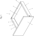
- a drawer 1 comprises a base 2, which is surrounded at the edges by a front panel 3 and a rear wall 4, as well as two side frames 5.
- the side frames 5 connect the front panel 3 to the rear wall 4 and have an inner wall 6 arranged on the side of the base 2 and an outer wall 7 on the side facing away from the base 2.
- the inner wall 6 and the outer wall 7 are connected to one another at an upper edge by a strip-shaped cover element 8.
- a side frame 5 is shown in detail.
- the side frame 5 includes a groove 13 on the inner wall 6 for receiving the plate-shaped base 2.
- a hollow chamber 11 is formed between the inner wall 6 and the outer wall 7, in which means for fastening the front panel 3 are arranged.
- holders 12 for fixing the rear wall 4 are provided in the hollow chamber 11.
- the inner wall 6 and the outer wall 7 are each made of a bent metal sheet, but can optionally also be formed integrally with one another.
- the strip-shaped cover element 8 has a web-shaped strip 9 on the side facing the hollow chamber 11, which serves to fix the cover element 8.
- several fastening elements 14 are provided in the hollow chamber 11, into which the strip 9 can be inserted.
- a magnetic foil 10 is fixed to the outer wall 7, which is applied over the entire vertical wall section of the outer wall 7.
- the magnetic foil 10 can also be smaller than the vertical wall surface of the outer wall 7.
- the magnetic foil 10 is shown in detail.
- the magnetic foil 10 has an adhesive side that can be attached to the inner wall 6 or the outer wall 7, and a decorative surface that can be colored or printed, for example with symbols, markings, logos, or other elements.
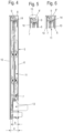
- FIG 4 is a sectional view through the side frame 5 in the assembled position. It can be seen that in the hollow chamber 11 between Inner wall 6 and outer wall 7 functional parts are arranged. In particular, a plurality of fastening elements 14 for fixing the strips 9 of the strip-shaped cover element 8 are arranged in the upper region. In the mounted position, the cover element 8 covers an upper edge of the magnetic film 10.
- the magnetic film 10 can, for example, have a thickness of between 0.6 mm and 2.5 mm.
- the magnetic film 10 is at least partially colored black or unprinted.
- An upper edge of the magnetic film 10 is at least partially, preferably completely, covered by the strip-shaped cover element 8.
- a lateral edge of the cover element 8 can be aligned flush with a surface of the magnetic film 10 in order to ensure a visually appealing appearance.
- FIG. 5 A modified cover element 8' is shown, which instead of a flat upper edge has a curve 15 extending from an outer side of the magnetic foil 10 to the inner wall 6.
- the geometry of the cover elements 8 and 8' can be designed to be flexible at the upper side.
- FIG. 6 A modified embodiment of a side frame 5 is shown, in which a magnetic foil 10 is fixed to both the inner wall 6 and the outer wall 7. The two upper edges of the magnetic foils 10 are covered by the strip-shaped cover element 8".
- the cover element 8" is fixed to the fastening elements 14 as in the previous embodiments.
- the width of the cover element 8, 8' and 8" can be adapted to the thickness of the magnetic foils 10.
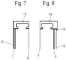
- FIG. 7 A further exemplary embodiment is shown schematically, in which a magnetic foil 10 is fixed to an outer wall 7, and an upper edge of the magnetic foil 10 is covered by a modified cover element 18.
- the cover element 18 is strip-shaped and has a U-shaped cross-sectional contour.
- the cover element 18 can engage around a holding element on the inner wall 6 and/or outer wall 7.
- the cover element 18 is aligned substantially flush with an inner side of the inner wall 6 and a surface of the magnetic foil 10.
- FIG 8 A modified cover element 18' is shown, which has a different cross-sectional contour and covers a magnetic foil 10 at an upper edge, which is fixed to an inner wall 6 of a side frame.
- the cover element 18' is not flush with the upper side of the magnetic foil 10, but has a web 19, which forms an outer surface of the Magnetic foil 10 is slightly overlapped, for example, between 0.5 mm and 5 mm. This web 19 allows the magnetic foil 10 to be positioned slightly recessed.
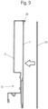
- FIG 9 A further embodiment of a side frame is shown, in which the inner wall 6 and the outer wall 7 are formed integrally with one another from a bent metal sheet.
- a cover element 28 is also formed integrally with the inner wall 6 and the outer wall 7 on the upper side.
- This cover element has a small overhang on the side of the outer wall 7, which approximately corresponds to the thickness of the magnetic foil 10, so that the upper edge of the magnetic foil 10 is covered by the overhang in the mounted position.
- Figure 10 is a opposite Figure 9 A modified embodiment is shown, in which a magnetic foil 10 is fixed to both the inner wall 6 and the outer wall 7 of the side frame 5. Both magnetic foils 10 are covered at their upper edge in the mounted position by a projection of the cover element 28, which is formed integrally with the inner wall 6 and the outer wall 7. Each projection is formed by a bend in the metal sheet.
- FIG 11 A modified embodiment of a side frame is shown in which a magnetic foil 10 is attached only to the inner wall 6.
- a cover element 28 on the upper side is formed integrally with the inner wall 6 and the outer wall 7 and has an overhang on the inner side that covers an upper edge of the magnetic foil 10 in the mounted position.
- a magnetic foil 10 can be attached either over the entire surface or only partially to the inner wall 6 and/or the outer wall 7. If the magnetic foil 10 covers only part of the surface of the inner wall 6 or the outer wall 7, a receptacle for the magnetic foil 10 can be formed so that both the upper edge of the magnetic foil 10 is covered by the cover element 8, 8', 8", 18, or 28, as well as a lower edge of the magnetic foil 10.
Landscapes
- Shielding Devices Or Components To Electric Or Magnetic Fields (AREA)
- Casings For Electric Apparatus (AREA)
Description
- Die vorliegende Erfindung betrifft eine Seitenzarge für einen Schubkasten, mit einer Innenwand, einer Außenwand und einem Abdeckelement an einer oberen Kante zwischen Innenwand und Außenwand, wobei die Innenwand und/oder die Außenwand aus einem gebogenen Metallblech hergestellt ist oder sind, wobei an einer Innenseite der Seitenzarge ein Kanal zur Aufnahme eines Bodens und in der Seitenzarge Mittel zur Aufnahme einer Frontblende und einer Rückwand ausgebildet sind.
- Die
EP 3 496 570 B1 offenbart eine Seitenzarge für einen Schubkasten, bei der eine Innenschale und eine Außenschale vorgesehen sind, zwischen denen Mittel zur Befestigung einer Frontblende oder Rückwand vorgesehen sind. An einer oberen Kante der Seitenzarge kann ein Abdeckelement fixiert sein. Die optische Gestaltungsmöglichkeit an den Oberflächen einer solchen Seitenzarge ist begrenzt. - Für solche Seitenzargen ist es aus der
WO 2018/033464 bekannt, eine obere Abdeckleiste in unterschiedlichen Formen optisch ansprechend zu gestalten. Die Innenwand und die Außenwand sind dabei aus einem gebogenen Metallblech hergestellt und meist einfarbig gehalten. -
DE 40 04 332 A1 offenbart ein ausgeschäumtes Schubladenwand-Hohlkammerprofil, das aus Metall hergestellt sein kann. - In der
DE 20 2014 102 595 U1 ist eine Hohlkammerzarge für eine Schublade offenbart, an der an einer Oberfläche ein Dekorelement angebracht ist. - Es ist daher Aufgabe der vorliegenden Erfindung, eine Seitenzarge für einen Schubkasten zu schaffen, bei der eine Oberfläche optisch variabel gestaltet werden kann.
- Diese Aufgabe wird mit einer Seitenzarge mit den Merkmalen des Anspruches 1 gelöst.
- Bei der erfindungsgemäßen Seitenzarge ist an einer Innenwand und/oder einer Außenwand eine Magnetfolie fixiert, deren obere Kante zumindest teilweise durch ein Abdeckelement an einer oberen Kante zwischen Innenwand und Außenwand überdeckt ist. Dadurch kann über die Magnetfolie eine Oberfläche der Seitenzarge individuell gestaltet werden, wobei eine Kante der Oberfläche, die meist schwarz eingefärbt ist, durch das Abdeckelement zumindest teilweise überdeckt ist, so dass kein Rand der Magnetfolie sichtbar ist.
- Vorzugsweise ist die obere Kante der Magnetfolie vollständig durch das Abdeckelement überdeckt, so dass eine Schnittkante der Magnetfolie oder ein Rand nicht sichtbar sind. Eine Außenseite des Abdeckelementes kann dabei flächenbündig mit einer Vorderseite der Magnetfolie abschließen, optional kann das Abdeckelement auch einen oberen Abschnitt der Magnetfolie überdecken.
- Für einen kompakten Aufbau können die Innenwand und die Außenwand zumindest in einem Bereich unterhalb des Abdeckelementes parallel zueinander ausgerichtet sein.
- Für eine effektive Befestigung der Magnetfolie können die Innenwand und/oder die Außenwand aus einem gebogenen Metallblech hergestellt sein. Die Innenwand und/oder Außenwand ist mit einer Deckschicht versehen, die z.B. als Lackierung, Pulverbeschichtung o.ä. aufgebracht sein kann. Die Magnetfolie kann somit mittelbar bzw. unmittelbar haftend auf der Innenwand und/oder der Außenwand aufgebracht werden.
- Die Magnetfolie weist vorzugsweise eine Dicke zwischen 0,3 mm bis 2,5 mm, insbesondere 0,8 mm bis 2 mm, auf, so dass diese biegbar ist und an die Kontur der Innenwand und/oder Außenwand angepasst werden kann. Dabei kann die Magnetfolie die Innenwand und/oder die Außenwand vollflächig überdecken. Alternativ kann auch nur eine teilweise Überdeckung vorgesehen werden. Für eine optisch besonders ansprechende Ausgestaltung kann die Magnetfolie bedruckt sein, beispielsweise mit Logos, Symbolen oder mit Text.
- Vorzugsweise schließt die Magnetfolie mit dem unteren Rand der Außenwand über die gesamte Länge bündig ab, so dass Spalte vermieden werden. Die Magnetfolie kann ferner mit dem oberen Rand des Kanals über die Länge zwischen der Rückwand und der Frontblende bündig abschließen.
- In einer weiteren Ausgestaltung ist zwischen der Innenwand und der Außenwand eine Hohlkammer ausgebildet, in der weitere Funktionselemente angeordnet sind. Beispielsweise kann in der Hohlkammer eine Vorrichtung zur Fixierung der Frontblende angeordnet sein. Ferner kann eine Vorrichtung zur Fixierung der Rückwand darin aufgenommen sein. An der Innenseite der Hohlkammer kann ein Kanal zur Aufnahme eines Bodens vorgesehen sein, der sich von der Innenwand bis bzw. bis nahe zur Innenseite der Außenwand erstreckt. Der Kanal zur Aufnahme des Bodens weist eine Breite von wenigstens 60% des Abstandes zwischen Innenwand und Außenwand im Bereich des Kanals auf. Der Kanal kann durch die Innenwand der Seitenzarge gebildet sein. Alternativ ist es möglich, dass der Kanal durch einen zur Innenwand separaten Bodenkanal oder durch mehrere separate Bodenkanaladapter gebildet wird.
- Die Innenwand der Seitenzarge ist hier vorzugsweise senkrecht zum Boden ausgerichtet, so dass ein maximales Stauvolumen in dem Schubkasten erreicht wird. Vorteilhaft ist bei einer senkrechten Innenwand auch die freie Verwendung von Innenorganisationen, die nicht an eine eventuelle Schrägfläche angepasst sein muss. Das Anbringen einer Magnetfolie auf der senkrechten Innenwand hat vorteilhafterweise nur einen geringen Einfluss auf den Innenbereich des Schubkastens. Auch eine störende Sichtkante an der Magnetfolienkante im unteren Bereich der Innenwand entsteht nicht bei einer senkrechten Innenwand.
- Das Abdeckelement kann an einer Oberseite der Seitenzarge zwischen Innenwand und Außenwand fixiert sein, beispielsweise über eine Leiste, die an einem oder mehreren Haltern in einem Hohlraum zwischen Innenwand und Außenwand angeordnet sind. Alternativ kann die Innenwand und/oder Außenwand im oberen Bereich eine Kontur zur Aufnahme des Abdeckelements aufweisen. Statt einer mechanischen Befestigung kann das Abdeckelement auch an der Oberseite verklebt sein oder magnetisch befestigt sein. Alternativ ist es möglich, das Abdeckelement auch integral mit der Innenwand und/oder der Außenwand auszubilden. Die Innenwand ist bevorzugt senkrecht zum Boden ausgerichtet.
- Das Abdeckelement ist erfindungsgemäß als separates Teil an einer Oberseite der Seitenzarge fixiert ist, wobei das Abdeckelement eine Leiste aufweist, die in die Seitenzarge eingreift und/oder das Abdeckelement einen oberen Bereich der Seitenzarge umgreift. Das Abdeckelement kann dabei wenigstens einen nach unten weisenden Steg aufweisen, der einen beabstandeten Bereich zur Seitenzarge ausbildet, mit dem ein Teil der Magnetfolie überdeckbar ist.
- Vorzugsweise erstreckt sich der Kanal von der Innenwand bis bzw. bis nahe zu einer Innenseite der Außenwand, wobei der Kanal eine Breite von wenigstens 60% des Abstandes zwischen Innenwand und Außenwand im Bereich des Kanals aufweist.
- In einer weiteren Ausgestaltung ist eine stirnseitige Schmalfläche der Magnetfolie am vorderen Ende der Seitenzarge von der Frontblende überdeckt.
- Die erfindungsgemäße Seitenzarge wird insbesondere an einem Schubkasten für Möbel oder Haushaltsgeräte eingebaut, bei dem an gegenüberliegenden Seiten jeweils eine Seitenzarge montiert ist, die eine Frontblende mit einer Rückwand verbindet.
- Die Erfindung wird nachfolgend anhand mehrerer Ausführungsbeispiele mit Bezug auf die beigefügten Zeichnungen näher erläutert. Es zeigen:
- Figur 1
- eine perspektivische Ansicht eines Schubkastens;
- Figur 2
- eine Explosionsdarstellung einer Seitenzarge für den Schubkasten;
- Figur 3
- eine Ansicht einer Magnetfolie ohne Seitenzarge;
- Figur 4
- eine Schnittansicht durch die Seitenzarge der
Figur 2 ; - Figur 5
- eine Schnittansicht durch eine modifizierte Seitenzarge;
- Figur 6
- eine Schnittansicht durch eine weitere Seitenzarge;
- Figur 7
- eine schematische Schnittansicht durch ein weiteres Ausführungsbeispiel einer Seitenzarge;
- Figur 8
- eine schematische Schnittansicht durch ein weiteres Ausführungsbeispiel;
- Figur 9
- eine Explosionsdarstellung einer weiteren nicht erfindungsgemäßen Seitenzarge;
- Figur 10
- eine Schnittansicht durch eine nicht erfindungsgemäße Seitenzarge mit zwei Magnetfolien, und
- Figur 11
- eine Schnittansicht durch eine weitere nicht erfindungsgemäße Seitenzarge.
- Ein Schubkasten 1 umfasst einen Boden 2, der randseitig von einer Frontblende 3 und einer Rückwand 4 sowie zwei Seitenzargen 5 umgeben ist. Die Seitenzargen 5 verbinden die Frontblende 3 mit der Rückwand 4 und weisen eine auf der Seite des Bodens 2 angeordnete Innenwand 6 sowie auf der von dem Boden 2 abgewandten Seite eine Außenwand 7 auf. Die Innenwand 6 und die Außenwand 7 sind an einer oberen Kante mit einem leistenförmigen Abdeckelement 8 miteinander verbunden.
- In
Figur 2 ist eine Seitenzarge 5 im Detail dargestellt. Die Seitenzarge 5 umfasst an der Innenwand 6 eine Nut 13 zur Aufnahme des plattenförmigen Bodens 2. Zwischen der Innenwand 6 und der Außenwand 7 ist eine Hohlkammer 11 ausgebildet, in der Mittel zur Befestigung der Frontblende 3 angeordnet sind. Im rückwärtigen Bereich sind in der Hohlkammer 11 Halter 12 zur Fixierung der Rückwand 4 vorgesehen. Die Innenwand 6 und die Außenwand 7 sind jeweils aus einem gebogenen Metallblech hergestellt, können optional aber auch integral miteinander ausgebildet sein. - Das leistenförmige Abdeckelement 8 weist auf der zu der Hohlkammer 11 gewandten Seite eine stegförmige Leiste 9 auf, die zur Fixierung des Abdeckelements 8 dient. Hierfür sind in der Hohlkammer 11 mehrere Befestigungselemente 14 vorgesehen, an denen die Leiste 9 eingesteckt werden kann.
- An der Außenwand 7 wird eine Magnetfolie 10 fixiert, die vollflächig auf den vertikalen Wandabschnitt der Außenwand 7 aufgebracht wird. Optional kann die Magnetfolie 10 auch eine geringere Größe aufweisen als die vertikale Wandfläche der Außenwand 7.
- In
Figur 3 ist die Magnetfolie 10 im Detail dargestellt. Die Magnetfolie 10 weist eine Haftseite auf, die an der Innenwand 6 oder der Außenwand 7 angebracht werden kann, und eine Dekorfläche, die farbig gestaltet oder bedruckt sein kann, beispielsweise mit Symbolen, Markierungen, Logos oder anderen Elementen. - In
Figur 4 ist eine Schnittansicht durch die Seitenzarge 5 in der montierten Position gezeigt. Es ist erkennbar, dass in der Hohlkammer 11 zwischen Innenwand 6 und Außenwand 7 Funktionsteile angeordnet sind. Insbesondere sind im oberen Bereich mehrere Befestigungselemente 14 zur Fixierung der Leisten 9 des leistenförmigen Abdeckelementes 8 angeordnet. Das Abdeckelement 8 überdeckt in der montierten Position eine obere Kante der Magnetfolie 10. Die Magnetfolie 10 kann beispielsweise eine Dicke zwischen 0,6 mm bis 2,5 mm aufweisen. Insbesondere ist die Magnetfolie 10 zumindest teilweise schwarz eingefärbt bzw. unbedruckt. Eine obere Kante der Magnetfolie 10 wird zumindest teilweise, vorzugsweise vollständig, durch das leistenförmige Abdeckelement 8 überdeckt. Eine seitliche Kante des Abdeckelementes 8 kann flächenbündig mit einer Oberfläche der Magnetfolie 10 ausgerichtet sein, um ein optisch ansprechendes Erscheinungsbild zu gewährleisten. - In
Figur 5 ist ein modifiziertes Abdeckelement 8' gezeigt, das statt einer flachen oberen Kante einen Bogen 15 aufweist, der sich von einer Außenseite der Magnetfolie 10 bis zu der Innenwand 6 erstreckt. Die Geometrie der Abdeckelemente 8 und 8' kann an der Oberseite flexible gestaltet werden. - In
Figur 6 ist eine modifizierte Ausgestaltung einer Seitenzarge 5 gezeigt, bei der sowohl an der Innenwand 6 als auch an der Außenwand 7 jeweils eine Magnetfolie 10 fixiert ist. Die beiden oberen Kanten der Magnetfolien 10 sind über das leistenförmige Abdeckelement 8" überdeckt. Das Abdeckelement 8" ist wie bei den vorangegangenen Ausführungsbeispielen an den Befestigungselementen 14 fixiert. Die Breite des Abdeckelementes 8, 8' und 8" kann an die Dicke der Magnetfolien 10 angepasst sein. - In
Figur 7 ist schematisch ein weiteres Ausführungsbeispiel gezeigt, bei dem an einer Außenwand 7 eine Magnetfolie 10 fixiert ist, und eine obere Kante der Magnetfolie 10 über ein modifiziertes Abdeckelement 18 überdeckt ist. Das Abdeckelement 18 ist leistenförmig ausgebildet und besitzt eine U-förmige Querschnittskontur. Dabei kann das Abdeckelement 18 ein Halteelement an der Innenwand 6 und/oder Außenwand 7 umgreifen. Das Abdeckelement 18 ist im Wesentlichen flächenbündig mit einer Innenseite der Innenwand 6 und einer Oberfläche der Magnetfolie 10 ausgerichtet. - In
Figur 8 ist ein modifiziertes Abdeckelement 18' gezeigt, das eine andere Querschnittskontur besitzt und eine Magnetfolie 10 an einer oberen Kante überdeckt, die an einer Innenwand 6 einer Seitenzarge fixiert ist. Das Abdeckelement 18' schließt aber nicht flächenbündig mit der Oberseite der Magnetfolie 10 ab, sondern weist einen Steg 19 auf, der eine Außenfläche der Magnetfolie 10 geringfügig überdeckt, beispielsweise zwischen 0,5 mm bis 5 mm. Durch diesen Steg 19 kann die Magnetfolie 10 leicht zurückversetzt angeordnet sein. - In
Figur 9 ist ein weiteres Ausführungsbeispiel einer Seitenzarge gezeigt, bei der die Innenwand 6 und die Außenwand 7 integral miteinander aus einem gebogenen Metallblech ausgebildet sind. Hierfür ist auch an der Oberseite ein Abdeckelement 28 integral mit der Innenwand 6 und der Außenwand 7 ausgebildet, das auf der Seite der Außenwand 7 einen kleinen Überstand aufweist, der in etwa der Dicke der Magnetfolie 10 entspricht, so dass die obere Kante der Magnetfolie 10 in der montierten Position durch den Überstand überdeckt ist. - In
Figur 10 ist ein gegenüberFigur 9 modifiziertes Ausführungsbeispiel gezeigt, bei dem sowohl an der Innenwand 6 als auch an der Außenwand 7 der Seitenzarge 5 eine Magnetfolie 10 fixiert ist. Beide Magnetfolien 10 sind an ihrer oberen Kante in der montierten Position durch einen Überstand des Abdeckelementes 28 überdeckt, das integral mit der Innenwand 6 und der Außenwand 7 ausgebildet ist. Jeder Überstand ist durch eine Umbiegung des Metallbleches gebildet. - In
Figur 11 ist eine modifizierte Ausgestaltung einer Seitenzarge gezeigt, bei der nur an der Innenwand 6 eine Magnetfolie 10 angebracht ist. Ein Abdeckelement 28 an der Oberseite ist integral mit der Innenwand 6 und der Außenwand 7 ausgebildet und besitzt einen Überstand an der Innenseite, der eine obere Kante der Magnetfolie 10 in der montierten Position überdeckt. - Die obigen Ausführungsbeispiele können beliebig miteinander kombiniert werden. Eine Magnetfolie 10 kann sowohl vollflächig als auch nur teilweise an der Innenwand 6 und/oder der Außenwand 7 angebracht sein. Wenn die Magnetfolie 10 nur einen Teil der Fläche der Innenwand 6 oder der Außenwand 7 überdeckt, kann eine Aufnahme für die Magnetfolie 10 ausgebildet sein, so dass sowohl die obere Kante der Magnetfolie 10 über das Abdeckelement 8, 8', 8", 18 oder 28 überdeckt ist, als auch eine untere Kante der Magnetfolie 10.
-
- 1
- Schubkasten
- 2
- Boden
- 3
- Frontblende
- 4
- Rückwand
- 5
- Seitenzarge
- 6
- Innenwand
- 7
- Außenwand
- 8, 8', 8"
- Abdeckelement
- 9
- Leiste
- 10
- Magnetfolie
- 11
- Hohlkammer
- 12
- Halter
- 13
- Nut
- 14
- Befestigungselement
- 15
- Bogen
- 18, 18'
- Abdeckelement
- 19
- Steg
- 28
- Abdeckelement
- b
- Breite
- a
- Abstand
Claims (13)
- Seitenzarge (5) für einen Schubkasten (1), mit einer Innenwand (6), einer Außenwand (7) und einem Abdeckelement (8, 8', 8", 18, 28) an einer oberen Kante zwischen Innenwand (6) und Außenwand (7), wobei die Innenwand (6) und/oder die Außenwand (7) aus einem gebogenen Metallblech hergestellt ist oder sind, wobei an einer Innenseite der Seitenzarge (5) ein Kanal (13) zur Aufnahme eines Bodens (2) und in der Seitenzarge (5) Mittel zur Aufnahme einer Frontblende (3) und einer Rückwand (4) ausgebildet sind, dadurch gekennzeichnet, dass an der Innenwand (6) und/oder der Außenwand (7) eine Magnetfolie (10) fixiert ist, deren obere Kante zumindest teilweise durch das Abdeckelement (8, 8', 8", 18) überdeckt ist, und das Abdeckelement (8, 8', 8", 18) als separates Teil an einer Oberseite der Seitenzarge (5) fixiert ist, wobei das Abdeckelement (8, 8', 8", 18) eine Leiste (9) aufweist, die in die Seitenzarge (5) eingreift und/oder das Abdeckelement (8, 8', 8", 18) einen oberen Bereich der Seitenzarge (5) umgreift.
- Seitenzarge (5) nach Anspruch 1, dadurch gekennzeichnet, dass die obere Kante der Magnetfolie (10) vollständig durch das Abdeckelement (8, 8', 8", 18, 28) überdeckt ist.
- Seitenzarge (5) nach Anspruch 1 oder 2, dadurch gekennzeichnet, dass die Innenwand (6) und die Außenwand (7) zumindest in einem Bereich unterhalb des Abdeckelement (8, 8', 8", 18) parallel zueinander ausgerichtet sind.
- Seitenzarge (5) nach einem der vorhergehenden Ansprüche, dadurch gekennzeichnet, dass die Magnetfolie (10) eine Dicke zwischen 0,6 mm bis 2,5 mm, insbesondere 0,8 mm bis 2 mm, aufweist.
- Seitenzarge (5) nach einem der vorhergehenden Ansprüche, dadurch gekennzeichnet, dass die Magnetfolie (10) die Innenwand (6) und/oder die Außenwand (7) vollflächig überdeckt.
- Seitenzarge (5) nach einem der vorhergehenden Ansprüche, dadurch gekennzeichnet, dass die Magnetfolie (10) mit dem unteren Rand der Außenwand (7) über die gesamte Länge bündig abschließt.
- Seitenzarge (5) nach einem der vorhergehenden Ansprüche, dadurch gekennzeichnet, dass die Magnetfolie (10) mit dem oberen Rand des Kanals (13) über die Länge zwischen der Rückwand (4) und der Frontblende (3) bündig abschließt.
- Seitenzarge (5) nach einem der vorhergehenden Ansprüche, dadurch gekennzeichnet, dass die Magnetfolie (10) bedruckt ist.
- Seitenzarge (5) nach einem der vorhergehenden Ansprüche, dadurch gekennzeichnet, dass das Abdeckelement (8, 8', 8", 18) wenigstens einen nach unten weisenden Steg (19) aufweist, der einen beabstandeten Bereich zur Seitenzarge (5) ausbildet, mit dem ein Teil der Magnetfolie (10) überdeckbar ist.
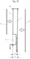
- Seitenzarge (5) nach einem der vorhergehenden Ansprüche, dadurch gekennzeichnet, dass sich der Kanal (13) von der Innenwand (6) bis bzw. bis nahe zu einer Innenseite der Außenwand (7) erstreckt, wobei der Kanal (13) eine Breite (b) von wenigstens 60% des Abstandes (a) zwischen Innenwand (6) und Außenwand (7) im Bereich des Kanals aufweist.
- Seitenzarge (5) nach einem der vorhergehenden Ansprüche, dadurch gekennzeichnet, dass die Innenwand (6) senkrecht zum Boden (2) ausgerichtet ist.
- Seitenzarge (5) nach einem der vorhergehenden Ansprüche, dadurch gekennzeichnet, dass eine stirnseitige Schmalfläche der Magnetfolie (10) am vorderen Ende der Seitenzarge (5) von der Frontblende (3) überdeckt wird.
- Schubkasten (1) mit mindestens einer Seitenzarge (5) nach einem der vorhergehenden Ansprüche.
Applications Claiming Priority (2)
| Application Number | Priority Date | Filing Date | Title |
|---|---|---|---|
| DE102021122180.3A DE102021122180A1 (de) | 2021-08-26 | 2021-08-26 | Seitenzarge für einen Schubkasten |
| PCT/EP2022/072139 WO2023025573A1 (de) | 2021-08-26 | 2022-08-05 | Seitenzarge für einen schubkasten |
Publications (2)
| Publication Number | Publication Date |
|---|---|
| EP4391867A1 EP4391867A1 (de) | 2024-07-03 |
| EP4391867B1 true EP4391867B1 (de) | 2025-05-28 |
Family
ID=83115335
Family Applications (1)
| Application Number | Title | Priority Date | Filing Date |
|---|---|---|---|
| EP22761220.7A Active EP4391867B1 (de) | 2021-08-26 | 2022-08-05 | Seitenzarge für einen schubkasten |
Country Status (4)
| Country | Link |
|---|---|
| EP (1) | EP4391867B1 (de) |
| CN (1) | CN117835871A (de) |
| DE (1) | DE102021122180A1 (de) |
| WO (1) | WO2023025573A1 (de) |
Families Citing this family (2)
| Publication number | Priority date | Publication date | Assignee | Title |
|---|---|---|---|---|
| DE102023130072A1 (de) * | 2023-10-31 | 2025-04-30 | Paul Hettich Gmbh & Co. Kg | Schubkasten und Verfahren zur Herstellung eines Schubkastens |
| DE102023130069A1 (de) * | 2023-10-31 | 2025-04-30 | Paul Hettich Gmbh & Co. Kg | Seitenzarge und Schubkasten |
Family Cites Families (6)
| Publication number | Priority date | Publication date | Assignee | Title |
|---|---|---|---|---|
| DE4004332A1 (de) * | 1990-02-13 | 1991-08-14 | Lautenschlaeger Kg Karl | Ausgeschaeumtes schubladenwand-hohlkammerprofil und verfahren zu seiner herstellung |
| DE202005008286U1 (de) | 2005-05-27 | 2006-10-05 | Paul Hettich Gmbh & Co. Kg | Schubkasten |
| DE202014102595U1 (de) | 2014-06-03 | 2015-09-04 | Grass Gmbh | Hohlkammerzarge für eine Schublade mit einem Zargenkörper, Schublade mit einer Hohlkammerzarge sowie Möbel mit einer solchen Schublade |
| DE102017110287A1 (de) | 2016-08-15 | 2018-02-15 | Paul Hettich Gmbh & Co. Kg | Zarge für einen Schubkasten |
| DE202017101022U1 (de) | 2017-02-23 | 2018-05-24 | Grass Gmbh | Hohlkammerzarge für eine Schublade, Schublade und Möbel |
| DE102018113851A1 (de) | 2018-06-11 | 2019-12-12 | Paul Hettich Gmbh & Co. Kg | Zarge für einen Schubkasten |
-
2021
- 2021-08-26 DE DE102021122180.3A patent/DE102021122180A1/de active Pending
-
2022
- 2022-08-05 EP EP22761220.7A patent/EP4391867B1/de active Active
- 2022-08-05 CN CN202280056749.0A patent/CN117835871A/zh active Pending
- 2022-08-05 WO PCT/EP2022/072139 patent/WO2023025573A1/de not_active Ceased
Also Published As
| Publication number | Publication date |
|---|---|
| WO2023025573A1 (de) | 2023-03-02 |
| EP4391867A1 (de) | 2024-07-03 |
| CN117835871A (zh) | 2024-04-05 |
| DE102021122180A1 (de) | 2023-03-02 |
Similar Documents
| Publication | Publication Date | Title |
|---|---|---|
| EP2611331B1 (de) | Möbelauszugsteil | |
| EP0380013B1 (de) | Vorrichtung zur Befestigung eines Dachhimmels einer Schiebedach- oder Schiebehebedachkonstruktion | |
| EP3496570B1 (de) | Zarge für einen schubkasten | |
| DE102012101220A1 (de) | Schubkasten | |
| DE202011110018U1 (de) | Schubladensystem | |
| EP2531066B1 (de) | Schubladenbehälter | |
| EP3579726B1 (de) | Schubkasten | |
| EP4391867A1 (de) | Seitenzarge für einen schubkasten | |
| AT391065B (de) | Schublade mit metallischen schubladenzargen | |
| DE102004037185B4 (de) | Verbindungsclip für ein Zierelement eines Kraftfahrzeugs | |
| EP3727088B1 (de) | Schubladenseitenwand | |
| EP2105063A1 (de) | Möbelkorpus | |
| DE2047112B2 (de) | Dreiteiliger halter aus kunststoff fuer tafeln von unterschiedlicher laenge, insbesondere fuer kraftfahrzeug-nummernschilder | |
| EP3628945B1 (de) | Tür für ein haushaltsgerät mit frontseitiger dekorplatte und kantenschutzelement für eine randkante der dekorplatte, sowie haushaltsgerät | |
| EP2730198A1 (de) | Griffelement für eine Frontplatte für Möbel | |
| DE20119391U1 (de) | Beschichtete Frontplatte für ein Küchenmöbel | |
| DE102007051924B4 (de) | Halte-Vorrichtung | |
| EP3408591B1 (de) | Halteeinrichtung zur befestigung von verkleidungsteilen an plattenheizkörpern und heizkörper | |
| DE202019104971U1 (de) | Schubkastenblende | |
| DE9413608U1 (de) | Beschlag für Türen und Fenster | |
| DE202006010077U1 (de) | Befestigungseinrichtung für einen Rauchmelder | |
| EP1990477B1 (de) | Leichtbauplatte mit einer Profilleiste | |
| DE29617065U1 (de) | Türschild | |
| DE29901509U1 (de) | Nachverformbare dekorative Hochdruck-Schichtpreßstoffplatte | |
| DE102012014613B4 (de) | Türinnenverkleidungsmodul einer Fahrzeugtüre |
Legal Events
| Date | Code | Title | Description |
|---|---|---|---|
| STAA | Information on the status of an ep patent application or granted ep patent |
Free format text: STATUS: UNKNOWN |
|
| STAA | Information on the status of an ep patent application or granted ep patent |
Free format text: STATUS: THE INTERNATIONAL PUBLICATION HAS BEEN MADE |
|
| PUAI | Public reference made under article 153(3) epc to a published international application that has entered the european phase |
Free format text: ORIGINAL CODE: 0009012 |
|
| STAA | Information on the status of an ep patent application or granted ep patent |
Free format text: STATUS: REQUEST FOR EXAMINATION WAS MADE |
|
| 17P | Request for examination filed |
Effective date: 20240320 |
|
| AK | Designated contracting states |
Kind code of ref document: A1 Designated state(s): AL AT BE BG CH CY CZ DE DK EE ES FI FR GB GR HR HU IE IS IT LI LT LU LV MC MK MT NL NO PL PT RO RS SE SI SK SM TR |
|
| DAV | Request for validation of the european patent (deleted) | ||
| DAX | Request for extension of the european patent (deleted) | ||
| GRAP | Despatch of communication of intention to grant a patent |
Free format text: ORIGINAL CODE: EPIDOSNIGR1 |
|
| STAA | Information on the status of an ep patent application or granted ep patent |
Free format text: STATUS: GRANT OF PATENT IS INTENDED |
|
| INTG | Intention to grant announced |
Effective date: 20250130 |
|
| GRAS | Grant fee paid |
Free format text: ORIGINAL CODE: EPIDOSNIGR3 |
|
| GRAA | (expected) grant |
Free format text: ORIGINAL CODE: 0009210 |
|
| STAA | Information on the status of an ep patent application or granted ep patent |
Free format text: STATUS: THE PATENT HAS BEEN GRANTED |
|
| P01 | Opt-out of the competence of the unified patent court (upc) registered |
Free format text: CASE NUMBER: APP_17838/2025 Effective date: 20250411 |
|
| AK | Designated contracting states |
Kind code of ref document: B1 Designated state(s): AL AT BE BG CH CY CZ DE DK EE ES FI FR GB GR HR HU IE IS IT LI LT LU LV MC MK MT NL NO PL PT RO RS SE SI SK SM TR |
|
| REG | Reference to a national code |
Ref country code: GB Ref legal event code: FG4D Free format text: NOT ENGLISH |
|
| REG | Reference to a national code |
Ref country code: CH Ref legal event code: EP |
|
| REG | Reference to a national code |
Ref country code: IE Ref legal event code: FG4D Free format text: LANGUAGE OF EP DOCUMENT: GERMAN Ref country code: DE Ref legal event code: R096 Ref document number: 502022004094 Country of ref document: DE |
|
| REG | Reference to a national code |
Ref country code: NL Ref legal event code: MP Effective date: 20250528 |
|
| PG25 | Lapsed in a contracting state [announced via postgrant information from national office to epo] |
Ref country code: FI Free format text: LAPSE BECAUSE OF FAILURE TO SUBMIT A TRANSLATION OF THE DESCRIPTION OR TO PAY THE FEE WITHIN THE PRESCRIBED TIME-LIMIT Effective date: 20250528 Ref country code: ES Free format text: LAPSE BECAUSE OF FAILURE TO SUBMIT A TRANSLATION OF THE DESCRIPTION OR TO PAY THE FEE WITHIN THE PRESCRIBED TIME-LIMIT Effective date: 20250528 |
|
| PGFP | Annual fee paid to national office [announced via postgrant information from national office to epo] |
Ref country code: DE Payment date: 20250819 Year of fee payment: 4 |
|
| REG | Reference to a national code |
Ref country code: LT Ref legal event code: MG9D |
|
| PG25 | Lapsed in a contracting state [announced via postgrant information from national office to epo] |
Ref country code: NO Free format text: LAPSE BECAUSE OF FAILURE TO SUBMIT A TRANSLATION OF THE DESCRIPTION OR TO PAY THE FEE WITHIN THE PRESCRIBED TIME-LIMIT Effective date: 20250828 Ref country code: GR Free format text: LAPSE BECAUSE OF FAILURE TO SUBMIT A TRANSLATION OF THE DESCRIPTION OR TO PAY THE FEE WITHIN THE PRESCRIBED TIME-LIMIT Effective date: 20250829 |
|
| PG25 | Lapsed in a contracting state [announced via postgrant information from national office to epo] |
Ref country code: PL Free format text: LAPSE BECAUSE OF FAILURE TO SUBMIT A TRANSLATION OF THE DESCRIPTION OR TO PAY THE FEE WITHIN THE PRESCRIBED TIME-LIMIT Effective date: 20250528 Ref country code: NL Free format text: LAPSE BECAUSE OF FAILURE TO SUBMIT A TRANSLATION OF THE DESCRIPTION OR TO PAY THE FEE WITHIN THE PRESCRIBED TIME-LIMIT Effective date: 20250528 |
|
| PGFP | Annual fee paid to national office [announced via postgrant information from national office to epo] |
Ref country code: TR Payment date: 20250819 Year of fee payment: 4 Ref country code: IT Payment date: 20250901 Year of fee payment: 4 |
|
| PG25 | Lapsed in a contracting state [announced via postgrant information from national office to epo] |
Ref country code: BG Free format text: LAPSE BECAUSE OF FAILURE TO SUBMIT A TRANSLATION OF THE DESCRIPTION OR TO PAY THE FEE WITHIN THE PRESCRIBED TIME-LIMIT Effective date: 20250528 |
|
| PG25 | Lapsed in a contracting state [announced via postgrant information from national office to epo] |
Ref country code: HR Free format text: LAPSE BECAUSE OF FAILURE TO SUBMIT A TRANSLATION OF THE DESCRIPTION OR TO PAY THE FEE WITHIN THE PRESCRIBED TIME-LIMIT Effective date: 20250528 |
|
| PGFP | Annual fee paid to national office [announced via postgrant information from national office to epo] |
Ref country code: AT Payment date: 20251020 Year of fee payment: 4 |
|
| PG25 | Lapsed in a contracting state [announced via postgrant information from national office to epo] |
Ref country code: RS Free format text: LAPSE BECAUSE OF FAILURE TO SUBMIT A TRANSLATION OF THE DESCRIPTION OR TO PAY THE FEE WITHIN THE PRESCRIBED TIME-LIMIT Effective date: 20250828 |
|
| PG25 | Lapsed in a contracting state [announced via postgrant information from national office to epo] |
Ref country code: IS Free format text: LAPSE BECAUSE OF FAILURE TO SUBMIT A TRANSLATION OF THE DESCRIPTION OR TO PAY THE FEE WITHIN THE PRESCRIBED TIME-LIMIT Effective date: 20250928 |
|
| PG25 | Lapsed in a contracting state [announced via postgrant information from national office to epo] |
Ref country code: LV Free format text: LAPSE BECAUSE OF FAILURE TO SUBMIT A TRANSLATION OF THE DESCRIPTION OR TO PAY THE FEE WITHIN THE PRESCRIBED TIME-LIMIT Effective date: 20250528 |
|
| PG25 | Lapsed in a contracting state [announced via postgrant information from national office to epo] |
Ref country code: SM Free format text: LAPSE BECAUSE OF FAILURE TO SUBMIT A TRANSLATION OF THE DESCRIPTION OR TO PAY THE FEE WITHIN THE PRESCRIBED TIME-LIMIT Effective date: 20250528 Ref country code: DK Free format text: LAPSE BECAUSE OF FAILURE TO SUBMIT A TRANSLATION OF THE DESCRIPTION OR TO PAY THE FEE WITHIN THE PRESCRIBED TIME-LIMIT Effective date: 20250528 |
|
| PG25 | Lapsed in a contracting state [announced via postgrant information from national office to epo] |
Ref country code: CZ Free format text: LAPSE BECAUSE OF FAILURE TO SUBMIT A TRANSLATION OF THE DESCRIPTION OR TO PAY THE FEE WITHIN THE PRESCRIBED TIME-LIMIT Effective date: 20250528 |
|
| PG25 | Lapsed in a contracting state [announced via postgrant information from national office to epo] |
Ref country code: EE Free format text: LAPSE BECAUSE OF FAILURE TO SUBMIT A TRANSLATION OF THE DESCRIPTION OR TO PAY THE FEE WITHIN THE PRESCRIBED TIME-LIMIT Effective date: 20250528 |
|
| PG25 | Lapsed in a contracting state [announced via postgrant information from national office to epo] |
Ref country code: SK Free format text: LAPSE BECAUSE OF FAILURE TO SUBMIT A TRANSLATION OF THE DESCRIPTION OR TO PAY THE FEE WITHIN THE PRESCRIBED TIME-LIMIT Effective date: 20250528 |
|
| REG | Reference to a national code |
Ref country code: DE Ref legal event code: R097 Ref document number: 502022004094 Country of ref document: DE |
|
| PG25 | Lapsed in a contracting state [announced via postgrant information from national office to epo] |
Ref country code: RO Free format text: LAPSE BECAUSE OF FAILURE TO SUBMIT A TRANSLATION OF THE DESCRIPTION OR TO PAY THE FEE WITHIN THE PRESCRIBED TIME-LIMIT Effective date: 20250528 |
|
| REG | Reference to a national code |
Ref country code: CH Ref legal event code: H13 Free format text: ST27 STATUS EVENT CODE: U-0-0-H10-H13 (AS PROVIDED BY THE NATIONAL OFFICE) Effective date: 20260324 |
|
| PG25 | Lapsed in a contracting state [announced via postgrant information from national office to epo] |
Ref country code: MC Free format text: LAPSE BECAUSE OF FAILURE TO SUBMIT A TRANSLATION OF THE DESCRIPTION OR TO PAY THE FEE WITHIN THE PRESCRIBED TIME-LIMIT Effective date: 20250528 |
|
| PLBE | No opposition filed within time limit |
Free format text: ORIGINAL CODE: 0009261 |
|
| STAA | Information on the status of an ep patent application or granted ep patent |
Free format text: STATUS: NO OPPOSITION FILED WITHIN TIME LIMIT |
|
| REG | Reference to a national code |
Ref country code: CH Ref legal event code: L10 Free format text: ST27 STATUS EVENT CODE: U-0-0-L10-L00 (AS PROVIDED BY THE NATIONAL OFFICE) Effective date: 20260409 |
|
| PG25 | Lapsed in a contracting state [announced via postgrant information from national office to epo] |
Ref country code: LU Free format text: LAPSE BECAUSE OF NON-PAYMENT OF DUE FEES Effective date: 20250805 |
|
| PG25 | Lapsed in a contracting state [announced via postgrant information from national office to epo] |
Ref country code: CH Free format text: LAPSE BECAUSE OF NON-PAYMENT OF DUE FEES Effective date: 20250831 |
|
| 26N | No opposition filed |
Effective date: 20260303 |