EP4393341A2 - Mehrschichtige folien zur verwendung in airbags und schuhwerk - Google Patents
Mehrschichtige folien zur verwendung in airbags und schuhwerk Download PDFInfo
- Publication number
- EP4393341A2 EP4393341A2 EP24176423.2A EP24176423A EP4393341A2 EP 4393341 A2 EP4393341 A2 EP 4393341A2 EP 24176423 A EP24176423 A EP 24176423A EP 4393341 A2 EP4393341 A2 EP 4393341A2
- Authority
- EP
- European Patent Office
- Prior art keywords
- layers
- gas
- bladder
- article
- footwear
- Prior art date
- Legal status (The legal status is an assumption and is not a legal conclusion. Google has not performed a legal analysis and makes no representation as to the accuracy of the status listed.)
- Granted
Links
Images








Classifications
-
- A—HUMAN NECESSITIES
- A43—FOOTWEAR
- A43B—CHARACTERISTIC FEATURES OF FOOTWEAR; PARTS OF FOOTWEAR
- A43B13/00—Soles; Sole-and-heel integral units
- A43B13/02—Soles; Sole-and-heel integral units characterised by the material
- A43B13/12—Soles with several layers of different materials
- A43B13/125—Soles with several layers of different materials characterised by the midsole or middle layer
-
- A—HUMAN NECESSITIES
- A43—FOOTWEAR
- A43B—CHARACTERISTIC FEATURES OF FOOTWEAR; PARTS OF FOOTWEAR
- A43B13/00—Soles; Sole-and-heel integral units
- A43B13/14—Soles; Sole-and-heel integral units characterised by the constructive form
- A43B13/18—Resilient soles
- A43B13/20—Pneumatic soles filled with a compressible fluid, e.g. air, gas
-
- A—HUMAN NECESSITIES
- A43—FOOTWEAR
- A43B—CHARACTERISTIC FEATURES OF FOOTWEAR; PARTS OF FOOTWEAR
- A43B13/00—Soles; Sole-and-heel integral units
- A43B13/14—Soles; Sole-and-heel integral units characterised by the constructive form
- A43B13/18—Resilient soles
- A43B13/181—Resiliency achieved by the structure of the sole
- A43B13/186—Differential cushioning region, e.g. cushioning located under the ball of the foot
-
- A—HUMAN NECESSITIES
- A43—FOOTWEAR
- A43B—CHARACTERISTIC FEATURES OF FOOTWEAR; PARTS OF FOOTWEAR
- A43B13/00—Soles; Sole-and-heel integral units
- A43B13/14—Soles; Sole-and-heel integral units characterised by the constructive form
- A43B13/18—Resilient soles
- A43B13/187—Resiliency achieved by the features of the material, e.g. foam, non liquid materials
- A43B13/188—Differential cushioning regions
-
- A—HUMAN NECESSITIES
- A43—FOOTWEAR
- A43B—CHARACTERISTIC FEATURES OF FOOTWEAR; PARTS OF FOOTWEAR
- A43B13/00—Soles; Sole-and-heel integral units
- A43B13/14—Soles; Sole-and-heel integral units characterised by the constructive form
- A43B13/18—Resilient soles
- A43B13/20—Pneumatic soles filled with a compressible fluid, e.g. air, gas
- A43B13/206—Pneumatic soles filled with a compressible fluid, e.g. air, gas provided with tubes or pipes or tubular shaped cushioning members
-
- B—PERFORMING OPERATIONS; TRANSPORTING
- B32—LAYERED PRODUCTS
- B32B—LAYERED PRODUCTS, i.e. PRODUCTS BUILT-UP OF STRATA OF FLAT OR NON-FLAT, e.g. CELLULAR OR HONEYCOMB, FORM
- B32B1/00—Layered products having a non-planar shape
-
- B—PERFORMING OPERATIONS; TRANSPORTING
- B32—LAYERED PRODUCTS
- B32B—LAYERED PRODUCTS, i.e. PRODUCTS BUILT-UP OF STRATA OF FLAT OR NON-FLAT, e.g. CELLULAR OR HONEYCOMB, FORM
- B32B27/00—Layered products comprising a layer of synthetic resin
- B32B27/06—Layered products comprising a layer of synthetic resin as the main or only constituent of a layer, which is next to another layer of the same or of a different material
- B32B27/08—Layered products comprising a layer of synthetic resin as the main or only constituent of a layer, which is next to another layer of the same or of a different material of synthetic resin
-
- B—PERFORMING OPERATIONS; TRANSPORTING
- B32—LAYERED PRODUCTS
- B32B—LAYERED PRODUCTS, i.e. PRODUCTS BUILT-UP OF STRATA OF FLAT OR NON-FLAT, e.g. CELLULAR OR HONEYCOMB, FORM
- B32B2307/00—Properties of the layers or laminate
- B32B2307/70—Other properties
- B32B2307/724—Permeability to gases, adsorption
-
- B—PERFORMING OPERATIONS; TRANSPORTING
- B32—LAYERED PRODUCTS
- B32B—LAYERED PRODUCTS, i.e. PRODUCTS BUILT-UP OF STRATA OF FLAT OR NON-FLAT, e.g. CELLULAR OR HONEYCOMB, FORM
- B32B2307/00—Properties of the layers or laminate
- B32B2307/70—Other properties
- B32B2307/732—Dimensional properties
- B32B2307/737—Dimensions, e.g. volume or area
- B32B2307/7375—Linear, e.g. length, distance or width
- B32B2307/7376—Thickness
-
- B—PERFORMING OPERATIONS; TRANSPORTING
- B32—LAYERED PRODUCTS
- B32B—LAYERED PRODUCTS, i.e. PRODUCTS BUILT-UP OF STRATA OF FLAT OR NON-FLAT, e.g. CELLULAR OR HONEYCOMB, FORM
- B32B2439/00—Containers; Receptacles
- B32B2439/40—Closed containers
- B32B2439/46—Bags
Definitions
- the present disclosure is directed to multi-layered films. More specifically, the present disclosure relates to multi-layered films having gas-barrier properties, methods of making such multi-layered films, articles incorporating the multi-layered films (e.g., airbags, fuel hose liners, and vehicle tires), and methods for manufacturing such articles. The present disclosure also relates to articles of footwear that incorporate the airbags.
- Articles of footwear conventionally include an upper and a sole structure.
- the upper may be formed from any suitable material(s) to receive, secure, and support a foot on the sole structure.
- the upper may cooperate with laces, straps, or other fasteners to adjust the fit of the upper around the foot.
- Sole structures generally include a layered arrangement extending between a ground surface and the upper.
- One layer of the sole structure includes an outsole that provides abrasion-resistance and traction with the ground surface.
- the outsole may be formed from rubber or other materials that impart durability and wear-resistance, as well as enhance traction with the ground surface.
- Another layer of the sole structure includes a midsole disposed between the outsole and the upper.
- the midsole provides cushioning for the foot and may be partially formed from a polymer foam material that compresses resiliently under an applied load to cushion the foot by attenuating ground-reaction forces.
- Sole structures may also include a comfort-enhancing insole or a sockliner located within a void proximate to the bottom portion of the upper and a strobel attached to the upper and disposed between the midsole and the insole or sockliner.
- the present disclosure is directed to a multi-layered film (e.g., microlayer film) having thin gas-barrier layers, which have been found to increase film flexibility while also retaining good film durability and gas-barrier properties.
- the multi-layered film of the present disclosure is suitable for use in a variety of articles requiring gas-barrier and/or gas-retention properties, e.g., airbags, fuel hose liners, vehicle tires, and the like.
- the multi-layered film is particularly suitable for use in articles that require gas-barrier and/or gas-retention properties while also being subjected to repeated flexing conditions, such as airbags for use in footwear cushioning (referred to as "airsoles," as defined below).
- Bladders having bulbous protrusions and/or areas of relatively small radii of curvature may be more likely to crack. Therefore, these types of bladders are at particular risk of visible defects. They are also at risk of an unacceptable increase in gas transmission rate resulting from aligned cracks in many, even all, layers (catastrophic cracking). There has therefore been a general reluctance in the present field to produce these types of bladders commercially, particularly bladders which are used as cushioning elements, as they will be exposed to a very large number of flexing and release cycles during use.
- the more crack- and craze-resistant multi-layered films disclosed herein may be used to make bladders (for example, cushioning elements) with a wider variety of shapes and for a wider variety of uses, than has previously been possible.
- Cushioning elements having bulbous protrusions and/or areas of relatively small radii of curvature may be made, which maintain high clarity and low gas diffusion rates for long periods of use.
- airbag and “bladder” are interchangeable and each refers to either a fluid-inflated and sealed component or a fluid-inflatable and sealable component, the latter of which can be inflated with one or more fluids and sealed.
- sealed and sealable terms can refer to fixed seals (e.g., with welded seams) and/or to dynamic seals that can switch between open and closed states (e.g., with valves).
- the airbags discussed herein can each have a single interior cavity that can be inflated with a fluid, multiple interior cavities that are separate and can be independently inflated with one or more fluids, and/or multiple interior cavities that are fluidly connected (at least some of them) and that can be inflated with one or more fluids, and combinations thereof.
- the term "airsole” refers to an airbag used as cushioning element in a footwear midsole component to provide cushioning and/or support to an article of footwear.
- the shape of a bladder typically includes an upper surface and a lower surface, with a sidewall positioned between the upper surface and the lower surface. While bladders may be shaped so that the sidewall includes either convex or concave curved regions, it is common for the sidewalls to include convex regions which curve away from and extend beyond the upper surface of the bladder or from the lower surface of the bladder or from both the upper surface and the lower surface of the bladder.
- the present disclosure is directed to the multi-layered film of aspect 6, wherein the one or more thermoplastic polyolefin homopolymers or copolymers comprise or consist essentially of one or more thermoplastic ethylene-vinyl alcohol copolymers.
- the present disclosure is directed to the multi-layered film of any one of the preceding aspects, wherein the elastomeric material comprises or consists essentially of one or more thermoplastic elastomeric polyurethane homopolymers or copolymers, optionally wherein the elastomeric material comprises or consists essentially of one or more polydiene polyol-based thermoplastic elastomeric polyurethane homopolymers or copolymers.
- the present disclosure is directed to the multi-layered film of aspect 23 or 24, wherein the melting temperature of the gas-barrier material is within about 10 degrees Celsius of the melting temperature of the elastomeric material, optionally within about 8 degrees Celsius of the melting temperature of the elastomeric material, or within about 5 degrees Celsius of the melting temperature of the elastomeric material.
- the present disclosure is directed to the multi-layered film of aspect 26 or 27, wherein the one or more second thermoplastics comprise or consist essentially of thermoplastic polypropylene homopolymers or copolymers, thermoplastic polyethylene homopolymers or copolymers, thermoplastic polybutylene homopolymers or copolymers, or any combination thereof.
- the present disclosure is directed to the multi-layered film of aspect 39, wherein the recycled material comprises one or more recycled or reground thermoplastic polyurethane elastomers or one or more recycled or reground thermoplastic ethylene-vinyl alcohol copolymers or both.
- the present disclosure is directed to the multi-layered film of any one of aspects 45-57, wherein the multi-layered film has a structure of D-A-B-C-B-A-D, wherein A represents a structural layer, B represents a tie layer, C represents a core region, and D represents a cap layer.
- the present disclosure is directed to an article comprising the multi-layered film of any one of aspects 1-61 or 67, wherein the multi-layered film of the article comprises a series of three or more layers, including
- the present disclosure is directed to the article of aspect 68, wherein, in the multi-layered film, the second cap layer is present and wherein the first cap layer material and the second cap layer material are substantially the same.
- the present disclosure is directed to the article of any one of aspects 68-70, wherein, in the multi-layered film, the first cap layer inner surface is in contact with the core region first surface, or the optional second cap layer inner surface is in contact with the core region second surface, or both.
- the present disclosure is directed to the article of any one of aspects 68-75, wherein the multi-layered film of the article is configured as a series of five or more layers including one or more tie layers, each of the one or more tie layers including a tie layer first surface, a tie layer second surface opposing the tie layer first surface, and a tie layer thickness extending from the tie layer first surface to the tie layer second surface;
- the present disclosure is directed to the article of aspect 76, wherein, in the multi-layered film, a first surface of a first one of the one or more tie layers is in contact with a second surface of a first one of the one or more structural layers, and the second surface of the first one of the one or more tie layers is in contact with a first surface of a core region; or wherein a first surface of a second one of the one or more tie layers is in contact with a second surface of one of the one or more core regions, and the second surface of the second one of the one or more tie layers is in contact with a first surface of a second one of the one or more structural layers, or both.
- the present disclosure is directed to the article of any one of aspects 76 or 77, wherein the multi-layered film of the article comprises a first cap layer, a first structural layer, a first tie layer, a core region, a second tie layer, a second structural layer, and a second cap layer, wherein the first cap layer inner surface contacts the first surface of the first structural layer, the second surface of the first structural layer contacts the first surface of the first tie layer, the second surface of the first tie layer contacts the first surface of the core region, the second surface of the core region contacts the first surface of the second tie layer, the second surface of the second tie layer contacts the first surface of the second structural layer, and the second surface of the second structural layer contacts the inner layer of the second cap layer.
- the present disclosure is directed to the article any one of aspects 68-78, wherein the article is a layered sheet, optionally wherein the layered sheet is a coextruded layered sheet, or is a laminated layered sheet.
- the present disclosure is directed to the article of aspect 80, wherein the multi-layered film forms an external-facing layer of the cushioning element.
- the present disclosure is directed to the article of any one of aspects 80-82, wherein the cushioning element is a component of an article of footwear, apparel, or sporting equipment.
- the present disclosure is directed to an article comprising the multi-layered film of any one of aspects 1-61 or 67.
- the present disclosure is directed to the article of aspect 84, wherein the article comprises an article of footwear, a component of an article footwear, an article of apparel, a component of an article of apparel, an article of sporting equipment, a component of an article of sporting equipment, a personal protective article, a flexible flotation device, a rigid flotation device, a medical device, a prosthetic device, an orthopedic device, an accumulator, an article of furniture, or a component of an article of furniture.
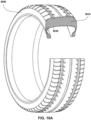
- the present disclosure is directed to the article of aspect 84, wherein the article comprises a tire or a hose.
- the present disclosure is directed to a consumer product produced by the method of aspect 87.
- the present disclosure is directed to a method for producing the multi-layered film of any one of aspects 1-61, comprising: co-extruding gas-barrier material and elastomeric material to form a multi-layered film comprising the one or more core regions.
- the present disclosure is directed to the method of any one of aspects 89-91, further comprising: applying at least one structural layer to the multi-layered film comprising the core region and the tie layer to form a multi-layered film comprising the one or more core regions, the tie layer, and the structural layer, wherein the structural layer comprises a structural layer material according to aspect 47.
- the present disclosure is directed to the method of aspect 92, further comprising: co-extruding at least one structural layer with the multi-layered film comprising the core region and the tie layer to form a multi-layered film comprising the one or more core regions, the tie layer, and the structural layer.
- the present disclosure is directed to the method of any one of aspects 89-93, further comprising: applying at least one cap layer to the multi-layered film comprising the core region, the tie layer, and the structural layer to form a multi-layered film comprising the core region, the tie layer, the structural layer, and the cap layer, wherein the cap layer comprises a cap layer material according to any one of aspects 51-53.
- the present disclosure is directed to the method of any one of aspects 89-93, further comprising: co-extruding at least one cap layer with the multi-layered film comprising the core region, the tie layer, and the structural layer to form a multi-layered film comprising the core region, the tie layer, the structural layer, and the cap layer.
- the present disclosure is directed to the bladder of aspect 96, wherein the first sheet and the second sheet are adhesively bonded or are thermally bonded, optionally wherein bladder includes a thermal bond formed by radio frequency welding between the first sheet and the second sheet.
- the present disclosure is directed to the bladder of aspect 96 or 97, wherein the bond is contiguous around the entire perimeter of the internal cavity and the internal cavity comprises a gas, optionally wherein the gas is a pressurized gas.
- the present disclosure is directed to the bladder of aspect 98, the gas comprises nitrogen gas or air.
- the present disclosure is directed to the bladder of any one of aspects 96-99, wherein the internal cavity has an initial internal pressure of from about 20 pounds per square inch (137.9 kilopascals) to about 22 pounds per square inch (151.7 kilopascals).
- the present disclosure is directed to the bladder of aspect 100, wherein after 2 years of use, the internal cavity has an inflation pressure of from at least about 70 percent to about 80 percent of the initial internal pressure.
- each of the gas-barrier layers has an average thickness ranging from about 0.5 micrometers to about 2 micrometers; or an average thickness in a range of from about 0.01 micrometer to about 0.75 micrometers, particularly in a range of from about 0.01 micrometers to about 0.5 micrometers.
- the present disclosure is directed to the bladder of any one of aspects 96-103, wherein the core region comprises at least 20, or at least 30, or at least 40, or at least 50 gas-barrier layers; optionally up to 70 gas-barrier layers.
- the present disclosure is directed to the bladder of any one of aspects 96-105, wherein the average total thickness of the core region ranges from about 125 micrometers to about 200 micrometers, and wherein the multi-layered film further comprises:
- the present disclosure is directed to the bladder of any one of aspects 96-106, wherein the structural layer material of each of the one or more structural layers independently comprises or consists essentially of a polydiene polyol-based thermoplastic polyurethane.
- the present disclosure is directed to the bladder of any one of aspects 96-107, further comprising one or more cap layers, wherein the one or more cap layers comprise or consist essentially of a cap layer material.
- each cap layer has a thickness ranging from about 5 micrometers to about 25 micrometers.
- the present disclosure is directed to the bladder of aspect 111, wherein the tie material of each of the one or more tie layers independently comprises or consists essentially of a polyurethane, a polyacrylate, an ethylene-acrylate copolymer, a maleic anhydride grafted polyolefin, or any combination thereof.
- the present disclosure is directed to the bladder of aspect 114, wherein the one or more bulbous protrusions are found in a heel portion of the airsole, a lateral portion of the airsole, a medial portion of the airsole, or any combination thereof.
- the present disclosure is directed to the bladder of aspect 116, wherein the bond between the first sheet and the second sheet forms
- the present disclosure is directed to the bladder of aspects 117 or 118, wherein the first chamber is aligned with the second chamber in the direction extending along the longitudinal axis of the bladder.
- the present disclosure is directed to the bladder of aspect 120, wherein the first leg, the second leg, the third leg, and the fourth leg extend in the same direction.
- the present disclosure is directed to the bladder of any one of aspects 120 or 121, wherein the first leg and the second leg are disposed between the first arcuate segment and the second arcuate segment.
- the present disclosure is directed to the bladder of aspect 124, wherein the third chamber is spaced apart from the first leg and the second leg.
- the present disclosure is directed to the bladder of aspect 126, wherein the fourth chamber is spaced apart from the third leg and the fourth leg.
- the present disclosure is directed to the bladder of aspect 126 or 127, wherein at least one of the third chamber or the fourth chamber is elongate.
- the present disclosure is directed to the bladder of any one of aspects 117-128, further comprising a web area defining the first chamber and the second chamber.
- the present disclosure is directed to the bladder of aspect 129, wherein the web area includes a first portion that is substantially U-shaped and a second portion that is substantially U-shaped.
- the present disclosure is directed to the bladder of any one of aspects 96-130, wherein the bladder does not exhibit cracking after at least 350,000 KIM cycles, or at least 400,000 KIM cycles.
- the present disclosure is directed to the bladder of any one of aspects 96-131, wherein the bladder has a gas transmission rate of no more than 120 percent of an original gas transmission rate after 320,000 KIM cycles.
- the present disclosure is directed to the bladder of any one of aspects 96-132, wherein the bladder has a gas transmission rate of from about 0.5 to about 2 cubic centimeters per square meter per day for nitrogen measured at 23 degrees Celsius and 0 percent relative humidity for a structure having a thickness of from about 72 micrometers to about 320 micrometers after from about 0 KIM cycles to about 320,000 KIM cycles.
- the present disclosure is directed to an article of footwear according to aspect 162 or 163, wherein the article of footwear further comprises a chassis secured to the upper.
- the present disclosure is directed to the article of footwear of any one of aspects 167-169, wherein the plurality of gas-barrier layers comprises at least 20 (for example, at least 30 or at least 40) gas-barrier layers; and, optionally, up to 70 gas-barrier layers.
- the present disclosure is directed to the article of footwear of any one of aspects 167-173, wherein the first height ranges from about 10 millimeters to about 24 millimeters.
- the present disclosure is directed to the article of footwear of aspect 174, wherein the first height ranges from about 15 millimeters to about 24 millimeters.
- the present disclosure is directed to the article of footwear of any one of aspects 167-179, wherein the plurality of elastomeric layers compositionally comprise one or more thermoplastic elastomeric polymers.
- the present disclosure is directed to the article of footwear of any one of aspects 167-180, wherein the plurality of elastomeric layers compositionally comprise a polyolefin copolymer, a polyester, a thermoplastic polyurethane, a styrenic block copolymer, or any combination thereof.
- the present disclosure is directed to the article of footwear of any one of aspects 167-185, further comprising a midsole chassis disposed between the upper and the airsole.
- the present disclosure is directed to the article of footwear of aspect 187, wherein a geometry of the bulbous heel portion in the compressed state defines a third vector extending from a rearward-most point of the compressed bulbous heel portion to the rearward-most point of the midsole chassis, and a fourth vector extending from the rearward-most point of the compressed bulbous heel portion to the rearward-most point of the outsole, and wherein the third vector and the fourth vector extends from each other at an angle ranging from about 38 degrees to about 107 degrees.
- the present disclosure is directed to the article of footwear of any one of aspects 167-188, further comprising a gas retained within the airsole.
- the present disclosure is directed to the article of footwear of any one of aspects 167-189, wherein the airsole has an initial inflation pressure ranging from about 20 pounds per square inch (137.9 kilopascals) to about 22 pounds per square inch (151.7 kilopascals).
- the present disclosure is directed to the article of footwear of aspect 190, wherein the multi-layered film is configured such that, after 1 year of use, the airsole retains an inflation pressure of at least about 70 percent of the initial inflation pressure, of at least 80 percent of the initial inflation pressure, or of at least 90 percent of the initial inflation pressure.
- the present disclosure is directed to the article of footwear of any one of aspects 167-192, wherein the bulbous heel portion does not exhibit visually-observable crazing after at least 350,000 KIM cycles, or at least 400,000 KIM cycles.
- the present disclosure is directed to the article of footwear of any one of aspects 167-193, wherein the airsole has a gas transmission rate of no more than 120 percent of an original gas transmission rate after 320,000 KIM cycles.
- the present disclosure is directed to a method of making a bladder according to any one of aspects 96-134 or 142-153, wherein the bladder comprises a first sheet and a second sheet, wherein a first side of the first sheet faces a second side of the second sheet, the method comprising:
- the present disclosure is directed to the method of aspect 196, wherein the bladder comprises one or more internal cavities, optionally wherein the one or more internal cavities includes at least two internal cavities, and optionally wherein each of the one or more internal cavities is an open cavity, or each of the one or more internal cavities is a sealed bladder, or the one or more internal cavities include at least one open cavity and at least one sealed bladder.
- the present disclosure is directed to the method of any one of aspects 196-198, wherein the method further comprises closing the one or more apertures in the perimeter of the internal cavity, thereby forming a sealed bladder.
- the present disclosure is directed to the method of aspect 199, wherein closing comprises forming an adhesive bond or a thermal bond between the first side of the first sheet and the second side of the second sheet at the one or more apertures.
- the present disclosure is directed to the method of any one of aspects 196-200, further comprising inflating the sealed bladder with a fluid.
- the present disclosure is directed to the method of any one of aspects 196-201, the method further comprising subjecting the bladder to a thermoforming step, optionally wherein the thermoforming step occurs before inflation of the bladder, or wherein the thermoforming step occurs simultaneously with inflation of the bladder, or wherein the thermoforming step occurs after inflation of the bladder, or any combination thereof.
- the present disclosure is directed to the method of aspect 202, wherein the bladder comprises an outer surface and wherein thermoforming comprises placing the bladder in a mold, wherein the mold comprises an inner molding surface.
- the present disclosure is directed to the method of aspect 203, wherein the inner molding surface contacts the outer surface of the bladder.
- the present disclosure is directed to the method of aspect 203, wherein a protective sheath having an outer surface is placed between at least a portion of the outer surface of the bladder and the inner molding surface, and wherein the outer surface of the protective sheath contacts the inner molding surface.
- the present disclosure is directed to the method of aspect 205, wherein the protective sheath comprises an inner surface, wherein the inner surface of the protective sheath contacts the outer surface of the bladder; optionally wherein the inner surface of the protective sheath comprises a raised pattern.
- the present disclosure is directed to the method of aspect 205 or 206, wherein the inner surface of the protective sheath comprises a raised pattern and wherein the raised pattern is imprinted into the bladder during thermoforming.
- thermoforming comprises increasing a temperature of the bladder to a softening temperature of the first sheet, the second sheet, or both, conforming the outer surface of the bladder to the shape of the inner molding surface.
- thermoforming further comprises applying a compressive force between the outer surface of the bladder and the inner molding surface, or optionally between the outer surface of the protective sheath and the inner molding surface.
- the present disclosure is directed to the method of aspect 209, wherein the compressive force provides a pressure differential between the outer surface of the bladder and the inner molding surface, or optionally between the outer surface of the protective sheath and the inner molding surface.
- the present disclosure is directed to the method of aspect 210, wherein the pressure differential is a positive pressure differential.
- the present disclosure is directed to the method of aspect 210, wherein the pressure differential is a negative pressure differential.
- the present disclosure is directed to a bladder made by the method of any one of aspects 196-212.
- the present disclosure is directed to a method for making an article of footwear, the method comprising: securing the bladder of any one of aspects 96-134 or 142-153 to an upper for an article of footwear.
- the present disclosure is directed to the method of aspect 214, further comprising securing the bladder of any one of aspects 96-134, 142-153, or 213 to an outsole and a midsole chassis, such that the bladder is disposed between the midsole chassis and the outsole to produce a sole structure; and securing the midsole chassis to an upper for an article of footwear.
- the present disclosure is directed to an article of footwear made by the method of aspect 214 or 215.
- an airbag can include a first sheet, a second sheet, or both a first sheet and a second sheet of the multi-layered film that are bonded together (e.g., thermally bonded) to form an internal cavity in a space between the first and second sheets, where the bond extends around at least a portion of a perimeter of the internal cavity.
- the internal cavity can be inflated with one or more fluids (e.g., one or more gases) during or after the bonding step.
- the bond extends around the entire perimeter of the internal cavity, providing a sealed airbag.
- the bond extends around only a portion of the entire perimeter (e.g., around most of the entire perimeter) and defines a sealable aperture configured to receive fluid(s)/gases(s) to the internal cavity.
- the resulting airbag when inflated and sealed, is capable of retaining the received fluid(s)/gases(s) in the internal cavity for extended usage due to the gas-barrier properties of the multi-layered film.
- the bladder can comprise a second multi-layered film, optionally wherein the structure of the second multi-layered film differs from the structure of the first multi-layered film in number of gas-barrier layers and elastomeric layers, or differs in thickness of gas-barrier layers and elastomeric layers, or differs in both number and thickness of gas- barrier layers and elastomeric layers.
- the multi-layered film includes one or more core regions, where each of the one or more core regions comprises multiple layers that alternate between thin gas-barrier layers (each having at least one gas-barrier material) and elastomeric layers (each having at least one elastomeric material).
- the gas-barrier material(s) of the gas-barrier layers and the elastomeric material(s) of the elastomeric layers have similar processing characteristics and can be co-extruded with reduced interlayer shear. This allows the alternating gas-barrier layers and elastomeric layers to be co-extended while retaining their structural integrities and desired layer thicknesses for use in the resulting multi-layered films.
- the gas-barrier materials of the gas-barrier layers are typically less flexible (e.g., more glass-like) than the elastomeric materials of the elastomeric layers.
- the elastomeric materials of the elastomeric layers may have a lower glass transition temperature than the gas-barrier materials of the gas-barrier layers, for example 20 degrees Celsius lower, particularly 50 degrees Celsius lower.
- the gas-barrier layers of the core region(s) are more susceptible to microscopic cracking when subjected to repeated, excessive stress loads, such as those potentially generated during flexing and release of the multi-layered film.
- each gas-barrier layer has an average layer thickness of less than about 2 micrometers, or from about 0.5 micrometers to about 2 micrometers, optionally less than about 0.5 micrometers, and a corresponding number of elastomeric layers such that each core region alternates between the gas-barrier layers and the elastomeric layers, can increase the flexibility of the core region(s), while maintaining the durability and gas-barrier properties of the multi-layered film.
- airbags incorporating the multi-layered film can be designed to withstand repeated flexing and release (e.g., by walking, running, and jumping) with reduced or no visually observable cracking, crazing, or hazing over extended usage.
- each gas-barrier layer has an average layer thickness of less than about 2 micrometers, optionally of less than about 0.75 micrometers, or optionally of less than about 0.5 micrometers, or in a range of from about 0.5 micrometers to about 2 micrometers, optionally in a range of from about 0.01 to about 0.75 micrometers, or optionally in a range of from about 0.01 to about 0.5 micrometers, and a corresponding number of elastomeric layers such that in each core region, the gas-barrier layers and the elastomeric layers alternate, can increase the flexibility of the core region(s), while maintaining the durability and gas-barrier properties of the multi-layered film.
- airbags incorporating the multi-layered film can be designed to withstand repeated flexing and release (e.g., by walking, running, and jumping) with reduced with reduced or no visually observable cracking, crazing, or hazing over extended usage.
- the multi-layered films and airbags, bladders, and other enclosed and/or hollow articles constructed therefrom are configured to withstand repeated flexing and release without cracking, crazing, or developing haze or other significant appearance changes.
- a bladder constructed from sheets comprising the multi-layered films can be incorporated as a cushioning element into a sole structure of an article of footwear. Further in this aspect, actions such as walking, running, and jumping may cause flexing and release of the bladder; however, bladders and other articles comprising the multi-layered films have a longer useful lifetime than known cushioning elements.
- disclosed herein is an article comprising the disclosed multi-layered films. In one aspect, the article is a cushioning element.
- the multi-layered film forms an external-facing layer of the cushioning element and is effective at retaining a fluid in the cushioning element.
- the cushioning element is a component of a consumer good such as an article of footwear, apparel, or sporting equipment.
- the cushioning element is a cushioning element for an article of footwear, and the cushioning element for the article of footwear is an airsole.
- each of the elastomeric layers can have an average thickness of from about 2 micrometers to about 8 micrometers, or from about 2 micrometers to about 5 micrometers, from about 5 micrometers to about 8 micrometers, or from about 4 micrometers to about 6 micrometers.
- the core region comprises at least 50 gas-barrier layers, or from about 50 to about 100 gas-barrier layers, from about 60 to about 80 gas-barrier layers, or from about 60 to about 70 gas-barrier layers. In one aspect, the core region comprises at least 50 elastomeric layers, or from about 50 to about 100 elastomeric layers, from about 60 to about 80 elastomeric, or from about 60 to about 70 elastomeric layers.
- the average total thickness of the core region ranges from about 125 to about 200 micrometers and the multi-layered film further includes a first structural layer secured to a first side of the core region, wherein the first structural layer has an average thickness of from about 900 micrometers to about 1990 micrometers, optionally from about 900 micrometers to about 1500 micrometers, from about 1500 micrometers to about 1990 micrometers, or from about 1000 micrometers to about 1400 micrometers; and a second structural layer secured to a second side of the core region that is opposite to the first side of the core region, wherein the second structural layer has an average thickness of from about 900 micrometers to about 1990 micrometers, optionally from about 900 micrometers to about 1500 micrometers, from about 1500 micrometers to about 1990 micrometers, or from about 1000 micrometers to about 1400 micrometers.
- the structural layer material of each of the one or more structural layers independently comprises or consists essentially of a polydiene polyol-based thermoplastic polyurethane.
- the disclosed bladders further include one or more cap layers comprising or consisting essentially of a cap layer material.
- the cap layer material of the one or more cap layers comprises or consists essentially of a polyurethane, a polyacrylate, an ethylene-acrylate copolymer, a maleic anhydride grafted polyolefin, or any combination thereof.
- each cap layer has a thickness of from about 5 micrometers to about 25 micrometers, or from about 5 micrometers to about 10 micrometers, or from about 10 micrometers to about 20 micrometers.
- the disclosed bladders further include one or more tie layers, each of the one or more tie layers comprising or consisting essentially of a tie material, wherein the one or more tie layers increase a bond strength between two adjacent layers.
- the tie material of each of the one or more tie layers independently comprises or consists essentially of a polyurethane, a polyacrylate, an ethylene-acrylate copolymer, a maleic anhydride grafted polyolefin, or any combination thereof.
- each of the one or more tie layers has a thickness of from about 5 micrometers to about 20 micrometers, or from about 5 micrometers to about 10 micrometers, or from about 10 micrometers to about 20 micrometers.
- the multi-layered films, airbags, or bladders disclosed herein may comprise or consist of one or more gas-barrier layers.
- a gas-barrier layer is understood to be a membrane comprising or consisting essentially of a gas-barrier material, where the thickness of the gas-barrier material in the gas-barrier layer is at least 0.01 microns.
- the gas-barrier material comprises or consists essentially of one or more gas-barrier compounds, including one or more polymeric gas-barrier compounds (i.e., gas-barrier polymers), or one or more non-polymeric gas-barrier compounds, or a combination of one or more gas-barrier polymers and one or more non-polymeric gas-barrier compounds.
- the other layers formed of elastomeric materials are referred to as "elastomeric layers," and the elastomeric material comprises or consists essentially of one or more elastomers, particularly one or more thermoplastic elastomers.
- a "core region" is an internal region of the multi-layered film in which the one or more gas-barrier layers are located. In many aspects, the core region comprises a plurality of individual gas-barrier layers each alternating with a layer formed of other materials.
- the core region comprises a plurality of gas-barrier layers each having an average thickness of less than or equal to about 0.75 micrometers, each of the gas-barrier layers alternating with an elastomeric layer, optionally at least 20 individual gas-barrier layers each alternating with an elastomeric layer.
- the core region resiliently retains the gas.
- the core region may retain the gas at a pressure which is above, at, or below atmospheric pressure. Examples of gasses include air, oxygen gas (O 2 ), and nitrogen gas (N 2 ), as well as inert gasses.
- the gas-barrier layer is a nitrogen gas-barrier layer.
- gas transmission rate of the core region of the multi-layered film or of the entire multi-layered film can be measured using ASTM D1434.
- the term "gas-barrier" material may refer to a material forming one or more layers in a core region of a multi-layered film, the core region of the multi-layered film having a total thickness less than or equal to 500 micrometers, optionally less than or equal to 300 micrometers, or less than or equal to 200 micrometers, or less than or equal to 100 micrometers, in which the core region, or the multi-layered film as a whole, has an oxygen gas or nitrogen gas transmission rate as measured using ASTM D1434 of less than or equal to about 4 cubic centimeters per square meter per day, optionally less than or equal to about 3 cubic centimeters per square meter per day.
- the gas-barrier layer comprise a multi-layered film comprising a plurality of layers, the plurality of layers comprising one or more gas-barrier layers, the one or more gas-barrier layers comprising a gas-barrier material, the gas-barrier material comprising or consisting essentially of one or more gas-barrier compounds.
- the multi-layered film comprises at least 5 layers or at least 10 layers.
- the multi-layered film comprises from about 5 to about 200 layers, from about 10 to about 100 layers, from about 20 to about 80 layers, from about 20 to about 50 layers, or from about 40 to about 90 layers.
- the multi-layered film may comprise about 20 or more gas-barrier layers, or about 30 or more gas-barrier layers, or about 40 or more gas-barrier layers, optionally fewer than 70 gas-barrier layers.
- the plurality of layers of the multi-layered film can include first gas-barrier layers comprising a first gas-barrier material and second gas-barrier layers comprising a second gas-barrier material, wherein the first and second gas-barrier materials differ from each other based as described above.
- the first gas-barrier material can be described as comprising a first gas-barrier component consisting of all the gas-barrier compounds present in the first gas-barrier material
- the second gas-barrier material can be described as comprising a second gas-barrier material component consisting of all the gas-barrier compounds present in the second gas-barrier material.
- the first gas-barrier component may consist only of one or more gas-barrier polymers, and the second gas-barrier component may consist only of one or more inorganic gas-barrier compounds.
- the first gas-barrier component may consist of a first one or more gas-barrier polymers, and the second gas-barrier component may consist of a second one or more gas-barrier polymers, wherein the first one or more gas-barrier polymers differ from the second one or more gas-barrier polymers in polymer class, type, or concentration.
- the first gas-barrier component and the second gas-barrier component may both include the same type of gas-barrier compound, but the concentration of the gas-barrier compound may differ, optionally the concentrations may differ by at least 5 weight percent based on the weight of the gas-barrier material.
- the first gas-barrier layers and the second gas-barrier layers may alternate with each other, or may alternate with additional gas-barrier layers (e.g., third gas-barrier layers comprising a third gas-barrier material, fourth gas-barrier layers comprising a fourth gas-barrier material, etc., wherein each of the first, second, third and fourth, etc., gas-barrier materials may differ from each other as described above).
- the total concentration of the inorganic gas-barrier component present in the gas-barrier material can be less than 60 weight percent, or less than 40 weight percent, or less than 20 weight percent of the total composition.
- the gas-barrier material may consist essentially of the one or more inorganic gas-barrier materials.
- gas-barrier polymers are known in the art.
- gas-barrier polymers include vinyl polymers such as vinylidene chloride polymers, acrylic polymers such as acrylonitrile polymers, polyamides, epoxy polymers, amine polymers, polyolefins such as polyethylenes and polypropylenes, copolymers thereof, such as ethylene-vinyl alcohol copolymers, and mixtures thereof.
- thermoplastic gas-barrier polymers include thermoplastic vinyl homopolymers and copolymers, thermoplastic acrylic homopolymers and copolymers, thermoplastic amine homopolymers and copolymers, thermoplastic polyolefin homopolymers and copolymers, and mixtures thereof.
- the one or more gas-barrier polymers may comprise or consist essentially of one or more thermoplastic polyethylene copolymers, such as, for example, one or more thermoplastic ethylene-vinyl alcohol copolymers.
- the one or more ethylene-vinyl alcohol copolymers may include from about 28 mole percent to about 44 mole percent ethylene content, or from about 32 mole percent to about 44 mole percent ethylene content.
- the one or more gas-barrier polymers may comprise or consist essentially of one or more polyethyleneimines, polyacrylic acids, polyethyleneoxides, polyacrylamides, polyamidoamines, or any combination thereof.
- the multi-layered film further comprises one or more second layers, the one or more second layers comprising a second material.
- the second material comprises one or more polymers.
- the one or more gas-barrier layers may include a plurality of gas-barrier layers alternating with a plurality of second layers.
- Each of the one or more barrier layers may be positioned between two second layers (e.g., with one second layer positioned on a first side of the barrier layer, and another second layer on a second side of the gas-barrier layer, the second side opposing the first side).
- the tensile breaking strength or ultimate strength of an elastomer may be greater than 70 kilogram-force per square centimeter, or greater than 80 kilogram-force per square centimeter.
- an elastomer, when formed into a plaque has a strain to break of from 450 percent to 800 percent, or from 500 to 800 percent, or from 500 to 750 percent, or from 600 to 750 percent, or from 450 to 700 percent.
- Polyesters are a class of polymers which include monomeric units derived from an ester functional group, and are commonly made by condensing dibasic acids such as, for example, terephthalic acid, with one or more polyols.
- the second material can comprise or consist essentially of one or more thermoplastic polyester elastomers.
- polyester polymers include homopolymers such as polyethylene terephthalate, polybutylene terephthalate, and poly-1,4-cyclohexylene-dimethylene terephthalate, as well as copolymers such as polyester polyurethanes.
- styrenic polymers include styrenic block copolymers, such as acrylonitrile butadiene styrene block copolymers, styrene acrylonitrile block copolymers, styrene ethylene butylene styrene block copolymers, styrene ethylene butadiene styrene block copolymers, styrene ethylene propylene styrene block copolymers, styrene butadiene styrene block copolymers, and combinations thereof.
- styrenic block copolymers such as acrylonitrile butadiene styrene block copolymers, styrene acrylonitrile block copolymers, styrene ethylene butylene styrene block copolymers, styrene ethylene butadiene styrene block copo
- Polyurethanes are a class of polymers which include monomeric units joined by carbamate linkages. Polyurethanes are most commonly formed by reacting a polyisocyanate (e.g., a diisocyanate or a triisocyanate) with a polyol (e.g., a diol or triol), optionally in the presence of a chain extender.
- a polyisocyanate e.g., a diisocyanate or a triisocyanate
- a polyol e.g., a diol or triol
- the monomeric units derived from the polyisocyanate are often referred to as the hard segments of the polyurethane, while the monomeric units derived from the polyols are often referred to as the soft segments of the polyurethane.
- the hard segments can be derived from aliphatic polyisocyanates, or from organic isocyanates, or from a mixture of both.
- suitable polyisocyanates from which the hard segments of the polyurethane can be derived include hexamethylene diisocyanate (HDI), isophorone diisocyanate (IPDI), butylenediisocyanate (BDI), bisisocyanatocyclohexylmethane (HMDI), 2,2,4-trimethylhexamethylene diisocyanate (TMDI), bisisocyanatomethylcyclohexane, bisisochanatomethyltricyclodecane, norbornane diisocyanate (NDI), cyclohexane diisocyanate (CHDI), 4,4'-dicyclohexhylmethane diisocyanate (H12MDI), diisocyanatododecane, lysine diisocyanate, toluene diisocyanate (TDI), TDI adducts with trimethylolpropane (TMP), methylene diphenyl diiso
- the barrier material when a co-extrusion process is used to form the barrier layer from a plurality of alternating barrier layers and second layers, has a melt flow index of from about 5 to about 7 grams per 10 minutes at 190 degrees Celsius when using a weight of 2.16 kilograms, while the second material has a melt flow index of from about 20 to about 30 grams per 10 minutes at 190 degrees Celsius when using a weight of 2.16 kilograms.
- the melt flow index of the barrier material is from about 80 percent to about 120 percent of the melt flow index of the barrier material per 10 minutes when measured at 190 degrees Celsius when using a weight of 2.16 kilograms.
- melt flow index can be measured using ASTM D1238.
- the barrier material or the second material or both have a melting temperature of from about 165 degrees Celsius to about 183 degrees Celsius, or from about 155 degrees Celsius to about 165 degrees Celsius.
- the barrier material has a melting temperature of from about 165 degrees Celsius to about 183 degrees Celsius
- the second material has a melting temperature of from about 155 degrees Celsius to about 165 degrees Celsius.
- melting temperature can be measured using ASTM D3418.
- the footwear 1010 is an example article of footwear that incorporates the multi-layered film of the present disclosure.
- the article of footwear 1010 can be divided lengthwise into one or more regions along a longitudinal axis A1010, such as into a forefoot region 1012, a mid-foot region 1014, and a heel region 1016.
- the forefoot region 1012 can be further described as including a toe portion corresponding to a portion of the footwear 1010 that surrounds the phalanges of a wearer's foot when worn, and a ball portion corresponding to a portion of the footwear 1010 that surrounds the metatarsophalangeal (MTP) joint of the wearer's foot when worn.
- MTP metatarsophalangeal
- the footwear 1010 can further include an anterior end 1018 associated with a forward-most location of the forefoot region 1012, and a posterior end 1020 corresponding to a rearward-most location of the heel region 1016.
- the longitudinal axis A1010 of the footwear 1010 extends along the length of the footwear 1010 from the anterior end 1018 to the posterior end 1020, and generally divides the footwear 1010 into a medial side 1022 and a lateral side 1024. Accordingly, the medial side 1022 and the lateral side 1024 respectively correspond with opposite sides of the footwear 1010 and extend through the regions 1012, 1014, and 1016.
- the upper 1026 can extend over the instep and toe areas of the wearer's foot (at the forefoot region 1012), along medial and lateral sides of the wearer's foot (at the mid-foot region 1014), and around the heel area of the wearer's foot (at the heel region 1016).
- the upper 1026 may be formed from one or more components that can be stitched, adhesively bonded, thermally bonded, or otherwise together to form the interior void, such as mesh, textiles, foam, leather, and synthetic leather.
- the materials may be selected and located to impart properties of durability, air-permeability, wear-resistance, flexibility, comfort, and the like. More specific examples of suitable materials for the upper 1026 are discussed below.
- the upper 1026 can also have any suitable design, shape, size, and/or colorway for footwear applications.
- the upper 1026 can be a high-top profile that is shaped to provide high support to a wearer's ankle.
- the upper 1026 can have a low-top profile.
- the sole structure 1028 includes a midsole 1030 configured to provide cushioning, support, and aesthetic characteristics, and an outsole 1032 configured to provide a ground-engaging surface of the footwear 1010.
- the midsole 1030 of the sole structure 1028 is further divided into multiple subcomponents that can provide different forms of cushioning, support, and aesthetics, such as a chassis 1034 and an airsole 1036.
- the chassis 1034 is depicted as having a single, full-length component extending from the forefoot region 1012 to the heel region 1016.
- the chassis 1034 may include multiple components, such as a first component extending from the forefoot region 1012 to the mid-foot region 1014 and a second component extending from the mid-foot region 1014 to the heel region 1016.
- the chassis 1034 may include multiple components providing zonal regions of cushioning and/or rigid support at forefoot region 1012, midfoot region 1014, and/or heel region 1016.
- the component(s) of the chassis 1034 may be pre-formed from any suitable resilient materials (e.g., foams and rubbers) and/or rigid materials (e.g., plates and molded parts).
- the component(s) of the chassis 1034 can include molded foam parts, loose foam beads retained in carrier shells, fused foam bead parts (e.g., by compression molding or steam chest molding), foam beads entrapped in a resilient polymeric resin matrix, and the like to impart properties of cushioning, responsiveness, support, and energy distribution to the wearer's foot.
- the chassis 1034 can include one or more semi-rigid plate components, such as carbon-fiber plates, polymeric (e.g., polyamide-based) plates, and the like.
- the chassis 1034 can be omitted and the airsole 1036 can be directly secured to the upper 1026.
- the outsole 1032 can have a geometry that matches the geometry of airsole 1036 and is configured to provide a ground-engaging surface of the footwear 1010.
- the outsole 1032 can be provided as a polymeric component that is overmolded onto, adhered to, or otherwise secured to the airsole 1036 to provide increased durability, puncture resistance, and/or abrasion resistance to the airsole 1036 in the ground-facing direction.
- suitable materials for the outsole 1032 include those capable of bonding to the airsole 1036 directly and/or with adhesives, and that preferably exhibit abrasion resistance and/or puncture resistance, such as polyurethanes, thermoplastic polyurethanes, polyether block amines, vulcanized rubbers, and combinations thereof.
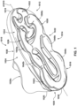
- the airsole 1036 is an example airbag for use with the footwear 1010 and incorporates the multi-layered film of the present disclosure.
- the multi-layered film exhibits an increased balance between durability and flexibility, while also retaining good gas-barrier properties.
- airsoles incorporating the multi-layered film can have a broader range of unique and advanced three-dimensional geometries than those achievable with current barrier films.
- the airsole 1036 can include one or more protruding and/or bulbous portions, such as a heel portion 1038 at the heel region 1016, medial portions 1040a, 1040b, and 1040c at the medial side 1022, and/or lateral portions 1042a, 1042b, and 1042c at the lateral side 1024.
- protruding portions particularly heel portion 1038, can potentially be subjected to high stress loads from flexing and release during each foot strike due to their extreme geometries, potentially resulting in significant flexing deformation of the multi-layered film and the barrier layers within. This is best illustrated in FIG.
- FIG. 4A is an expanded view of the heel portion 1038 at the heel region 1016 in an uncompressed state, such as when the footwear 1010 raised during a walking or running stride or when the footwear 1010 is sitting on an underlying surface (e.g., surface 1044) without any applied weight.
- an underlying surface e.g., surface 104
- heel portion 1038 is a bulbous, protruding portion having a height 1046 in an uncompressed state, where the height 1046 is distance from the top of the airsole 1036 at the chassis 1034 to the bottom of the airsole 1036 at the outsole 1032 as taken along an axis 1048 that is a vertical axis perpendicular to the surface 1044 when the footwear 1010 is resting upright on the surface 1044.
- suitable heights 1046 can range from about 10 to about 24 millimeters, from about 10 to 20 millimeters, or from about 15 to about 24 millimeters.
- Heel portion 1038 further protrudes rearwardly from the chassis 1034 by a distance 1050 in a direction along or parallel to axis A1010.
- a point 1052 can be defined as a furthest rearward point on heel portion 1038 along axis A1010.
- the extent of the bulbous, protruding geometry of the heel portion 1038 can be defined by two vectors. These two vectors include a first vector 1054, which begins at point 1052 and extends through a rearward-most contact point 1056 between the chassis 1034 and the airsole 1036, and a second vector 1058 begins at point 1052 and extends through a rearward-most contact point 1060 between the outsole 1032 and the airsole 1036.
- an angle 1062 between the first vector 1054 through point 1056 and the second vector 1058 through point 1060 ranges from about 115 degrees to about 137.5 degrees, or from about 115 degrees to about 125 degrees, or from about 120 degrees to about 137.5 degrees.
- the bulbous, protruding geometry of the heel portion 1038 as can be independently characterized by the height 1046, the rearward distance 1050, and the angle 1062 is vertically unsupported by either outsole 1032 or chassis 1034.
- a greater rearward distance 1050 will subject the multi-layered film of the airsole 1036 at the location of point 1052 to greater the potential stress loads during each foot strike.
- suitable distances 1050 can range from about 4.5 millimeters to about 7.1 millimeters, or from about 4.5 millimeters to about 6.0 millimeters, or from about 6.0 millimeters to about 7.1 millimeters.
- FIG. 4B is an expanded view of the heel portion 1038 in a compressed state, such as when the footwear 1010 is receiving a load applied by a wearer's foot strike on the surface 1044.
- the heel portion 1038 in the compressed state, has a reduced height 1064, where height 1064 is a distance from the top of the airsole 1036 at the chassis 1034 to the bottom of the airsole 1036 at the outsole 1032, as taken along the axis 1048.
- suitable heights 1064 range from about 8.6 to about 13.6 millimeters, or from about 8.6 to about 11 millimeters, or from about 10 millimeters to about 13.6 millimeters.
- the heel portion 1038 protrudes rearwardly by a distance 1066 taken in direction along or parallel to the axis A1010.
- suitable distances 1066 range from about 6.4 millimeters to about 8.2 millimeters, or from about 6.4 millimeters to about 7.0 millimeters, or from about 7.0 millimeters to about 8.2 millimeters.
- a 200 pound weight is placed on the disclosed bladder and/or an article of footwear comprising the bladder.
- the bladder and/or article of footwear in a compressed state, is subjected to an applied force equivalent to that exerted by a 300 pound person wearing a pair of footwear including the bladders in a sole structure thereof.
- the height 1046 in the uncompressed state is greater than the height 1064 in the compressed state.
- suitable differences in heights 1046 and 1064 range from about 1.4 millimeters to about 10.4 millimeters, as measured by the Load Compression Test Protocol described in the Property Analysis and Characterization Procedures section herein.
- the height 1064 in the compressed state ranges from about 56.7 percent to about 86.0 percent of the height 1046 in the uncompressed state, as measured by the Load Compression Test Protocol.
- the differences between the uncompressed height 1046 and the compressed height 1064 are applicable at the time of manufacturing as well as within 3 months of use, within 6 months of use, within 1 year of use, or within 2 years of use.
- an inflated airsole that does not exhibit crazing or cracking after at least 320,000 KIM cycles or greater retains a low gas transmission rate and a high proportion of its inflation internal pressure, thus limiting the amount of compression possible and thus limiting compressed height 1064 as a proportion of uncompressed height 1046 after a period of regular use.
- the distance 1050 in the uncompressed state is less than the distance 1066 in the compressed state.
- suitable differences in the distances 1050 and 1066 range from about 1.1 millimeters to about 1.9 millimeters, as measured by the Load Compression Test Protocol.
- the suitable differences in distances are applicable at time of manufacturing, within 3 months of use, within 6 months of use, within 1 year of use, or within 2 years of use.
- distance 1050 in the uncompressed state ranges from about 70.3 percent to about 86.6 percent of the distance 1066 in the compressed state, as measured by the Load Compression Test Protocol.
- a point 1068 is furthest rearward point on heel portion 1038 along axis A1010 when the airsole is in the compressed state
- the point 1052 is the furthest rearward point on heel portion 1038 along axis A1010 when the airsole is in the uncompressed state.
- point 1068 and point 1052 are located on the same physical location of the heel portion 1038, while in other aspects, such as when the airsole 1036 has an asymmetrical shape and/or bend location, point 1068 and point 1052 can be located on different physical spots of the heel portion 1038.
- the bulbous, protruding geometry of the heel portion 1038 as can be independently characterized by the height 1064, the rearward distance 1066, and the angle 1074 is vertically unsupported by either outsole 1032 or chassis 1034.
- a greater rearward distance 1066 will subject the multi-layered film of the airsole 1036 at the location of point 1068 to greater potential stress loads during each foot strike.
- suitable distances 1066 can range from about 6.4 millimeters to about 8.2 millimeters, or from about 6.4 millimeters to about 7.0 millimeters, or from about 7.0 millimeters to about 8.2 millimeters.
- the angle 1074 in the compressed state is less than the angle 1062 in the uncompressed state.
- suitable differences in the angles 1062 and 1074 range from about 37.5 degrees to about 77 degrees, as measured by the Load Compression Test Protocol.
- the suitable differences in angles are applicable at time of manufacturing, within 3 months of use, within 6 months of use, within 1 year of use, or within 2 years of use.
- angle 1074 ranges from about 33.0 percent to about 77.8 percent of angle 1062, as measured by the Load Compression Test Protocol.
- the profile or shape of the airsole 1036 can be different from that depicted.
- the airsole 1036 can be made from two multi-layered films as disclosed herein, wherein the multi-layered films are sheets that are joined together around a perimeter.
- one sheet can be thermoformed and can, in some aspects, form the bottom of the airsole 1036 in partially in contact with the outsole 1032.
- a second sheet can form the top of the airsole 1036, wherein the second sheet may or may not be thermoformed and wherein the second sheet can be partially on contact with chassis 1034.
- the multi-layered film of the present disclosure can be used as a suitable replacement in any current gas-barrier applications that incorporate multi-layered films (e.g., microlayer films).
- the multi-layered film can be incorporated into airsoles having any suitable geometry, such as those disclosed in U.S. Patent Nos. 10,149,513 , 11,019,880 , and 11,019,881 and U.S. Patent Application Publication Nos. 2019/0231027 , 2020/0205514 , 2021/0145119 , and 2021/0195996 .
- This allows the same multi-layered film to be interchangeably used as feedstock for multiple different airsole geometries, thereby increasing manufacturing efficiency, reducing raw material waste, and reducing manufacturing carbon impact.
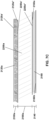
- multi-layered film 1076 is an example multi-layered film of the present disclosure, such as for use in the airsole 1036.
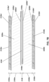
- the articles disclosed herein can comprise multiple layers as illustrated, for example, in FIG. 5 .
- the article is a sheet comprising gas-barrier layers and includes two structural layers, 2200a having a thickness 2180a and 2200b having a thickness 2180b and a core region or film 2160 having a thickness 2140.
- the article can be two-sided. Further in this aspect, a two-sided article can include a symmetrical arrangement of layers on both sides of core region 2160.
- Suitable examples of thicknesses 2180a and 2180b range from about 900 micrometers to about 1990 micrometers, or from about 900 micrometers to about 1400 micrometers, or from about 1400 micrometers to about 1990 micrometers.
- Suitable examples of thickness 2140 range from about 125 micrometers to about 200 micrometers, or from about 125 micrometers to about 175 micrometers, or from about 150 micrometers to about 200 micrometers.
- structural layers 2200a and 2200b can comprise or consist essentially of a structural layer material.
- the core region 2160 can comprise or consist essentially of a multi-layered film comprising gas-barrier layers as disclosed herein.
- structural layer 2200a can have a first surface 2200a' and a second surface 2200a", while structural layer 2200b can have a first surface 2200b' and a second surface 2200b".
- the core region 2160 can have a first surface 2160a and a second surface 2160b.
- the second surface 2200a" of the structural layer 2200a and the first surface 2160a of the core region 2160 can be adjacent to one another or otherwise in contact with one another.
- the second surface 2160b of the core region 2160 and the second surface 2200b" of the structural layer 2200b can be adjacent to one another or otherwise in contact with one another.
- first surface 2200a' of structural layer 2200a and/or first surface 2200b' of structural layer 2200b can independently optionally be an outer surface of an article incorporating the multi-layered film disclosed herein.
- structural layer 2200a and structural layer 2200 can be made from the same material or from different materials and can have the same or different thicknesses.
- articles comprising the multi-layered films disclosed herein, the articles including:
- the gas-barrier material comprises or consists essentially of a nitrogen barrier material.
- the gas-barrier material comprises or consists essentially of one or more gas-barrier polymers.
- the gas-barrier material can comprise a gas-barrier polymeric component consisting of all polymers present in the gas-barrier material.
- the one or more gas-barrier polymers comprise or consist essentially of one or more thermoplastic vinylidene chloride polymers, one or more thermoplastic acrylonitrile polymers or copolymers, one or more thermoplastic polyamides, one or more thermoplastic epoxy resins, one or more thermoplastic amine polymers or copolymers, or one or more thermoplastic polyolefin homopolymers or copolymers.
- the one or more thermoplastic polyolefin homopolymers or copolymers comprise or consist essentially of one or more thermoplastic polyethylene copolymers, or comprise or consist essentially of one or more thermoplastic ethylene-vinyl alcohol copolymers.
- the one or more ethylene-vinyl alcohol copolymers include from about 28 mole percent to about 44 mole percent ethylene content, or from about 32 mole percent to about 44 mole percent ethylene content.
- the elastomeric material comprises or consists essentially of one or more thermoplastic elastomeric polymers, and further comprises an elastomeric polymeric component consisting of all polymers present in the elastomeric material.
- the one or more thermoplastic elastomeric polymers comprise or consist essentially of one or more thermoplastic elastomeric polyolefin homopolymers or copolymers, one or more thermoplastic elastomeric polyamide homopolymers or copolymers, one or more thermoplastic elastomeric polyester homopolymers or copolymers, one or more thermoplastic elastomeric polyurethane homopolymers or copolymers, one or more thermoplastic elastomeric styrenic homopolymers or copolymers, or any combination thereof.
- the one or more styrenic homopolymers or copolymers can include one or more styrenic block copolymers, such as acrylonitrile butadiene styrene block copolymers, styrene acrylonitrile block copolymers, styrene ethylene butylene styrene block copolymers, styrene ethylene butadiene styrene block copolymers, styrene ethylene propylene styrene block copolymers, styrene butadiene styrene block copolymers, and combinations thereof.
- styrenic block copolymers such as acrylonitrile butadiene styrene block copolymers, styrene acrylonitrile block copolymers, styrene ethylene butylene styrene block copolymers, styrene
- the elastomeric material comprises or consists essentially of one or more thermoplastic elastomeric polyurethane homopolymers or copolymers, optionally wherein the elastomeric material comprises or consists essentially of one or more polydiene polyol-based thermoplastic elastomeric polyurethane homopolymers or copolymers.
- thermoplastic elastomeric polyurethane homopolymer or copolymer comprises or consists essentially of one or more polydiene polyol-based thermoplastic elastomeric polyurethane homopolymers or copolymers, wherein the polyol comprises or consists essentially of a polybutadiene polyol, a polyisoprene polyol, a partially or fully hydrogenated derivative of a polybutadiene polyol or of a polyisoprene polyol, or any combination thereof.
- the one or more polyols comprise or consist essentially of a polyester polyol, a polyether polyol, a polycarbonate polyol, a polycaprolactone polyether, or any combination thereof.
- the diisocyanate comprises or consists essentially of an aliphatic diisocyanate, an aromatic diisocyanate, or any combination thereof.
- the aliphatic diisocyanate comprises or consists essentially of hexamethylene diisocyanate (HDI), isophorone diisocyanate (IPDI), butylenediisocyanate (BDI), bisisocyanatocyclohexylmethane (HMDI), 2,2,4-trimethylhexamethylene diisocyanate (TMDI), bisisocyanatomethylcyclohexane, bisisochanatomethyltricyclodecane, norbornane diisocyanate (NDI), cyclohexane diisocyanate (CHDI), 4,4'-dicyclohexhylmethane diisocyanate (H12MDI), diisocyanatododecane, lysine diisocyanate, or any combination thereof.
- HDI he
- the aromatic diisocyanate comprises or consists essentially of toluene diisocyanate (TDI), TDI adducts with trimethylolpropane (TMP), methylene diphenyl diisocyanate (MDI), xylene diisocyanate (XDI), tetramethylxylylene diisocyanate (TMXDI), hydrogenated xylene diisocyanate (HXDI), naphthalene 1,5-diisocyanate (NDI), 1,5-tetrahydronaphthalene diisocyanate, para-phenylene diisocyanate (PPDI), 3,3'-dimethyldiphenyl-4,4'-diisocyanate (DDDI), 4,4'-dibenzyl diisocyanate (DBDI), 4-chloro-1,3-phenylene diisocyanate, or any combination thereof.
- TMP trimethylolpropane
- MDI methylene dipheny
- the gas-barrier material in the multi-layered films, can have a melt flow index of from about 5 to about 7 grams per 10 minutes at 190 degrees Celsius when using a weight of 2.16 kilograms. In another aspect, the elastomeric material can have a melt flow index of from about 20 to about 30 grams per 10 minutes at 190 degrees Celsius when using a weight of 2.16 kilograms.
- the melt flow index of the gas-barrier material can be from about 80 percent to about 120 percent of the melt flow index of the elastomeric material, or from about 90 percent to about 110 percent of the melt flow index of the elastomeric material, from about 95 percent to about 105 percent of the melt flow index of the elastomeric material, or can be substantially the same as the melt flow index of the elastomeric material, when the melt flow index is measured in cubic centimeters per 10 minutes at 190 degrees Celsius when using a weight of 2.16 kilograms.
- the gas-barrier material can have a melting temperature of from about 165 degrees Celsius to about 183 degrees Celsius, while in another aspect, the elastomeric material can have a melting temperature of from about 155 degrees Celsius to about 165 degrees Celsius. In any of these aspects, the melting temperature of the gas-barrier material is within about 10 degrees Celsius of the melting temperature of the elastomeric material, optionally within about 8 degrees Celsius of the melting temperature of the elastomeric material, or within about 5 degrees Celsius of the melting temperature of the elastomeric material.
- the multi-layered films disclosed herein further comprise a blended material, wherein the blended material comprises or consists essentially of a blend of one or more additional thermoplastic elastomers and a second material, optionally wherein the second material comprises or consists essentially of one or more second polymers, optionally wherein the one or more second polymers comprise or consist essentially of one or more second thermoplastics.
- the one or more second thermoplastics can comprise or consist essentially of thermoplastic polypropylene homopolymers or copolymers, thermoplastic polyethylene homopolymers or copolymers, thermoplastic polybutylene homopolymers or copolymers, or any combination thereof.
- the one or more second thermoplastics comprise or consist essentially of one or more thermoplastic polyethylene copolymers. In another aspect, the one or more second thermoplastics comprise or consist essentially of one or more thermoplastic ethylene-vinyl alcohol copolymers. In one aspect, a polymeric component of the blended material consists of one or more additional thermoplastic elastomeric polyurethane homopolymers or copolymers, and one or more second thermoplastic ethylene-vinyl alcohol copolymers. In an alternative aspect, the polymeric component of the thermoplastic elastomeric material consists of one or more additional thermoplastic elastomeric polyester-polyurethane copolymers and one or more second thermoplastic ethylene-vinyl alcohol copolymers. In some aspects, the blended material comprises one or more recycled additional thermoplastic elastomers, or one or more recycled second thermoplastics, or both.
- the blended material is a phase-separated blend of the one or more additional thermoplastic elastomers and the one or more second thermoplastics.
- the phase-separated blend includes one or more phase-separated regions including interfaces between the one or more additional thermoplastic elastomers and the one or more second thermoplastics.
- the blend comprises about 95 percent by weight of the one or more second thermoplastics and about 5 percent by weight of the one or more second thermoplastics based on a total weight of the blend.
- the term recycled material may refer to a polymeric material which has previously been extruded into a film, and may have been previously thermoformed into a bladder, before being shredded or ground and re-extruded into a film.
- the thermal history of a material may provide evidence that it is a recycled material, rather than a virgin material.
- a recycled material, particularly a recycled polymeric material may comprise up to 10 percent of a gas-barrier polymeric material on a weight basis, as it may have been recycled by grinding or shredding a multi-layered film that included a gas-barrier material.
- the recycled material comprises about 99 percent to about 50 percent by weight of recycled or reground polymers based on a total weight of recycled material, or from about 99 percent to about 75 percent by weight of recycled or reground polymers.
- the multi-layered film further comprises one or more tie layers, each of the one or more tie layers individually comprising or consisting essentially of a tie material, wherein the one or more tie layers increase a bond strength between two adjacent layers.
- the tie material of each of the one or more tie layers independently comprises or consists essentially of a polyurethane, a polyacrylate, an ethylene-acrylate copolymer, a maleic anhydride grafted polyolefin, or any combination thereof, and optionally the tie material comprises or consists essentially of a blended material or a recycled material as disclosed herein.
- the elastomeric material can be a first elastomeric material
- the multi-layered films further include a second elastomeric material
- the formed multi-layered film further comprises a first structural layer secured to a first side of one of the one or more core regions, wherein the first structural layer comprises the second elastomeric material and has an average thickness ranging from about 900 micrometers to about 1990 micrometers, optionally from about 900 to about 1500 micrometers, from about 1500 to about 1990 micrometers, from about 1200 to about 1800 micrometers, or from about 1000 to about 1400 micrometers.
- the multi-layered films further comprise one or more structural layers, each of the one or more structural layers independently comprising or consisting essentially of a structural layer material, optionally wherein the structural layer material comprises or consists essentially of a blended material or a recycled material as described herein.
- the structural layer material of the one or more structural layers independently comprises or consists essentially of a polydiene polyol-based thermoplastic polyurethane.
- each of the one or more core regions comprises a plurality of layers, the plurality of layers comprising gas-barrier layers 3020 comprising at least one gas-barrier material alternating with elastomeric layers 3010 comprising at least one elastomeric material; wherein each of the gas-barrier layers has a thickness 3021 of from about 0.5 micrometers to about 2 micrometers thick, or from about 0.5 micrometers to about 1 micrometer thick; or optionally less than or equal to 0.75 micrometers thick, or less than or equal to 0.5 micrometers thick, or in a range of from about 0.01 micrometers to about 0.75 micrometers thick, particularly in a range of from about 0.01 micrometers to about 0.5 micrometers thick; and wherein each of the elastomeric layers has a thickness 3011 of from about 2 micrometers to about 8 micrometers thick, or from
- Suitable examples of thickness 2140 range from about 125 micrometers to about 200 micrometers, or from about 125 micrometers to about 175 micrometers, or from about 150 micrometers to about 200 micrometers.
- Suitable examples of thicknesses 2100a and 2100b range from about 5 micrometers to about 25 micrometers.
- the article can be two-sided. Further in this aspect, a two-sided article can include a symmetrical arrangement of layers on both sides of core region 2160.
- the cap layer 2120a can have a first surface 2120a' and a second surface 2120a", while the cap layer 2120b can have a first surface 2120b' and a second surface 2120b".
- the structural layer 2200a can have a first surface 2200a' and a second surface 2200a", while the core region 2200b can have a first surface 2200b' and a second surface 2200b".
- the core region 2160 can have a first surface 2160a and a second surface 2160b.
- the second surface 2120a" of the cap layer 2120a and the first surface 2200a' of the structural layer 2200a can be adjacent to one another or otherwise in contact with one another.
- first surface 2120a' of cap layer 2120a and/or first surface 2120b' of cap layer 2120b can independently optionally be an outer surface of an article incorporating the multi-layered film disclosed herein.
- structural layer 2200a and structural layer 2200b can be made from the same material or from different materials and can have the same or different thicknesses.
- cap layer 2120a and cap layer 2120b can be made from the same material or from different materials and can have the same or different thicknesses.
- the one or more structural layers comprise or consist essentially of the blended material or the recycled material as disclosed herein.
- the articles disclosed herein can comprise multiple layers as illustrated, for example, in FIG. 7D .
- the article is a sheet comprising gas-barrier layers and includes two cap layers, specifically cap layer 2120a (having a thickness 2100a), cap layer 2120b (having a thickness 2100b); two structural layers, specifically structural layer (2200a having a thickness 2180a), structural layer 2200b (having a thickness 2180b); two tie layers, specifically tie layer 2240a (having a thickness 2220a) and tie layer 2240b (having a thickness 2220b); and a core region or layer 2160 (having a thickness 2140).
- a sheet or multi-layered film can incorporate single structural layer 2200a comprising a structural material, single cap layer 2120a comprising a cap layer material, single tie layer 2240a comprising a tie layer material, and core region 2160 comprising gas-barrier layers.
- the article can be configured as a series of five or more layers including one or more tie layers, each of the one or more tie layers including a tie layer first surface, a tie layer second surface opposing the tie layer first surface, and a tie layer thickness extending from the tie layer first surface to the tie layer second surface;
- a first surface of a first one of the one or more tie layers is in contact with a second surface of a first one of the one or more structural layers, and the second surface of the first one of the one or more tie layers is in contact with a first surface of a core region, or wherein a first surface of a second one of the one or more tie layers is in contact with a second surface of one of the one or more core regions, and the second surface of the second one of the one or more tie layers is in contact with a first surface of a second one of the one or more structural layers, or both.
- the article comprises the first cap layer, a first structural layer, a first tie layer, a core region, a second tie layer, a second structural layer, and the second cap layer, wherein the first cap layer inner surface contacts the first surface of the first structural layer, the second surface of the first structural layer contacts the first surface of the first tie layer, the second surface of the first tie layer contacts the first surface of the core region, the second surface of the core region contacts the first surface of the second tie layer, the second surface of the second tie layer contacts the first surface of the second structural layer, and the second surface of the second structural layer contacts the inner layer of the second cap layer, and optionally the core region comprises one or more core regions, or comprises a plurality of microlayers.
- One or both of the sheets comprising gas-barrier layers as shown in FIGs. 5 and 7A- 7E can independently be transparent, translucent, and/or opaque.
- transparent for a barrier layer and/or a bladder means that light passes through the barrier layer in substantially straight lines and a viewer can see through the barrier layer. In comparison, for an opaque barrier layer, light does not pass through the barrier layer and one cannot see clearly through the barrier layer at all.
- a translucent barrier layer falls between a transparent barrier layer and an opaque barrier layer, in that light passes through a translucent layer but some of the light is scattered so that a viewer cannot see clearly through the layer.
- the airsole 1036 can be produced from the sheets comprising gas-barrier layers as shown in FIGs. 5 and 7A -7E using any suitable technique, such as thermoforming (e.g. vacuum thermoforming), blow molding, extrusion, injection molding, vacuum molding, rotary molding, transfer molding, pressure forming, heat sealing, casting, low-pressure casting, spin casting, reaction injection molding, radio frequency (RF) welding, and the like.
- thermoforming e.g. vacuum thermoforming
- blow molding extrusion
- injection molding injection molding
- vacuum molding rotary molding
- transfer molding pressure forming
- heat sealing heat sealing
- casting low-pressure casting
- spin casting reaction injection molding
- radio frequency (RF) welding and the like.
- RF radio frequency
- 5 and 7A -7E can be produced by co-extrusion followed by vacuum thermoforming to form the profile of the airsole 1036 which can optionally include one or more valves (e.g., one way valves) that allows the airsole 1036 to be filled with the fluid (e.g., gas).
- the fluid e.g., gas
- the multi-layered films and articles produced therefrom are suitable for use in mass-market products including, but not limited to, articles of footwear, articles of sporting equipment, articles of athletic apparel, personal protective equipment, and the like.
- the multi-layered films and articles formed therefrom can include one or more textiles or, in the case of bladders or airbags, one or more spacer materials, wherein the spacer materials can be textiles, foamed components, 3D printed components, or other materials as described herein.
- Additional processes can be performed on the multi-layered films and/or articles formed therefrom, including, but not limited to, application of decorative elements and thermoforming to impart useful structures, shapes, or textures. Also disclosed are consumer products incorporating the multi-layered films and articles comprising the same and methods of making the consumer products.
- provided herein is a method for producing the multi-layered films disclosed herein, the method comprising co-extruding the gas-barrier material and the elastomeric material to form a multi-layered structure comprising the one or more core regions.
- the method further comprises applying at least one tie layer to the multi-layered film to form a multi-layered film comprising one or more core regions and the tie layer, wherein the tie layer comprises a tie material as described herein.
- the method comprises co-extruding at least one tie layer with the multi-layered film to form a multi-layered film comprising the one or more core regions and the tie layer.
- the method comprises applying at least one structural layer to the multi-layered film comprising the core region and the tie layer to form a multi-layered film comprising the one or more core regions, the tie layer, and the structural layer, wherein the structural layer comprises a structural layer material.
- the method can comprise co-extruding at least one structural layer with the multi-layered film comprising the core region and the tie layer to form a multi-layered film comprising the one or more core regions, the tie layer, and the structural layer.
- the method further comprises applying at least one cap layer to the multi-layered film comprising the core region, the tie layer, and the structural layer to form a multi-layered film comprising the core region, the tie layer, the structural layer, and the cap layer, wherein the cap layer comprises a cap layer material as described herein.
- the method further comprises co-extruding at least one cap layer with the multi-layered film comprising the core region, the tie layer, and the structural layer to form a multi-layered film comprising the core region, the tie layer, the structural layer, and the cap layer.
- the article is a layered sheet, optionally a coextruded layered sheet or a laminated layered sheet.
- the article can comprise an article of footwear, a component of an article of footwear, an article of apparel, a component of an article of apparel, an article of sporting equipment, a component of an article of sporting equipment, a personal protective article, a flexible flotation device, a rigid flotation device, a medical device, a prosthetic device, an orthopedic device, an accumulator, an article of furniture, or a component of an article of furniture.
- the article can be a tire or a hose.
- methods of manufacturing a consumer product the methods comprising affixing the disclosed articles to a second component.
- consumer products produced by the disclosed methods are also disclosed herein.
- a polymeric material comprising: one or more core regions, wherein each of the one or more core regions comprises a plurality of layers, the plurality of layers comprising gas-barrier layers comprising at least one gas-barrier material alternating with elastomeric layers comprising at least one elastomeric material, wherein each of the gas-barrier layers is from about 0.5 micrometers to about 2 micrometers thick, or from about 0.5 micrometers to about 1 micrometer thick; optionally less than or equal to 0.75 micrometers thick, or less than or equal to 0.5 micrometers thick, or in a range of from about 0.01 micrometers to about 0.75 micrometers thick, particularly in a range of from about 0.01 micrometers to about 0.5 micrometers thick; and wherein each of the elastomeric layers is from about 2 micrometers to about 8 micrometers thick, or from about 2 micrometers to about 4 micrometers thick.
- each of the one or more core regions comprises at least 50 layers, or from about 50 to about 100 layers, from about 50 to about 90 layers, from about 50 to about 80 layers, from about 50 to about 70 layers, from about 60 to about 100 layers, from about 60 to about 90 layers, or from about 60 to about 80 layers.
- the gas-barrier material comprises or consists essentially of one or more gas-barrier polymers, wherein the gas-barrier material comprises a gas-barrier polymeric component consisting of all polymers present in the gas-barrier material.
- the gas-barrier material comprises a nitrogen barrier material.
- the one or more gas-barrier polymers comprise or consist essentially of one or more thermoplastic vinylidene chloride polymers, one or more thermoplastic acrylonitrile polymers or copolymers, one or more thermoplastic polyamides, one or more thermoplastic epoxy resins, one or more thermoplastic amine polymers or copolymers, or one or more thermoplastic polyolefin homopolymers or copolymers.
- the one or more thermoplastic polyolefin homopolymers or copolymers comprise or consist essentially of one or more thermoplastic ethylene-vinyl alcohol copolymers.
- the one or more thermoplastic ethylene-vinyl alcohol copolymers include from about 28 mole percent to about 44 mole percent ethylene content, or from about 32 mole percent to about 44 mole percent ethylene content.
- the elastomeric material comprises or consists essentially of one or more thermoplastic elastomeric polymers, and comprises an elastomeric polymeric component consisting of all polymers present in the elastomeric material.
- the one or more thermoplastic elastomeric polymers comprise or consist essentially of one or more thermoplastic elastomeric polyolefin homopolymers or copolymers, one or more thermoplastic elastomeric polyamide homopolymers or copolymers, one or more thermoplastic elastomeric polyester homopolymers or copolymers, one or more thermoplastic elastomeric polyurethane homopolymers or copolymers, one or more thermoplastic elastomeric styrenic homopolymers or copolymers, or any combination thereof.
- the one or more styrenic homopolymers or copolymers can include one or more styrenic block copolymers, such as acrylonitrile butadiene styrene block copolymers, styrene acrylonitrile block copolymers, styrene ethylene butylene styrene block copolymers, styrene ethylene butadiene styrene block copolymers, styrene ethylene propylene styrene block copolymers, styrene butadiene styrene block copolymers, and combinations thereof.
- styrenic block copolymers such as acrylonitrile butadiene styrene block copolymers, styrene acrylonitrile block copolymers, styrene ethylene butylene styrene block copolymers, styrene
- the elastomeric material comprises or consists essentially of one or more thermoplastic elastomeric polyurethane homopolymers or copolymers, and optionally comprises or consists essentially of one or more polydiene polyol-based thermoplastic elastomeric homopolymers or copolymers.
- the one or more thermoplastic elastomeric polyurethane homopolymers or copolymers comprise a plurality of first segments derived from one or more polyols and a plurality of second segments derived from a diisocyanate.
- the one or more thermoplastic elastomeric polyurethane homopolymers or copolymers is a polymerization product of a diisocyanate with a polyol.
- the thermoplastic elastomeric polyurethane homopolymer or copolymer comprises or consists essentially of one or more polydiene polyol-based thermoplastic elastomeric polyurethane homopolymers or copolymers and the polyol comprises or consists essentially of a polybutadiene polyol, a polyisoprene polyol, a partially or fully-hydrogenated derivative of a polybutadiene polyol or of a polyisoprene polyol, or any combination thereof.
- the polyol comprises or consists essentially of a polyester polyol, a polyether polyol, a polycarbonate polyol, a polycaprolactone polyether, or any combination thereof.
- the diisocyanate can comprise or consist essentially of an aliphatic diisocyanate, an aromatic diisocyanate, or any combination thereof.
- the aliphatic diisocyanate comprises or consists essentially of hexamethylene diisocyanate (HDI), isophorone diisocyanate (IPDI), butylenediisocyanate (BDI), bisisocyanatocyclohexylmethane (HMDI), 2,2,4-trimethylhexamethylene diisocyanate (TMDI), bisisocyanatomethylcyclohexane, bisisochanatomethyltricyclodecane, norbornane diisocyanate (NDI), cyclohexane diisocyanate (CHDI), 4,4'-dicyclohexhylmethane diisocyanate (H12MDI), diisocyanatododecane, lysine diisocyanate, or any combination thereof.
- HDI he
- the aromatic diisocyanate comprises or consists essentially of toluene diisocyanate (TDI), TDI adducts with trimethylolpropane (TMP), methylene diphenyl diisocyanate (MDI), xylene diisocyanate (XDI), tetramethylxylylene diisocyanate (TMXDI), hydrogenated xylene diisocyanate (HXDI), naphthalene 1,5-diisocyanate (NDI), 1,5-tetrahydronaphthalene diisocyanate, para-phenylene diisocyanate (PPDI), 3,3'-dimethyldiphenyl-4,4'-diisocyanate (DDDI), 4,4'-dibenzyl diisocyanate (DBDI), 4-chloro-1,3-phenylene diisocyanate, or any combination thereof.
- TMP trimethylolpropane
- MDI methylene dipheny
- the multi-layered films disclosed herein and/or airbags or bladders incorporating the multi-layered films can include a spacer component in an internal cavity.
- the spacer material can comprise or consist essentially of a textile, a foamed component, an injection-molded component, a component produced by 3D printing or additive manufacturing, or any combination thereof.
- the foamed component can comprise or consist essentially of a plurality of foam particles.
- the spacer component additionally comprises a surrounding thermoplastic material as described herein.
- the spacer component can comprise a first layer, a second layer, and a plurality of connecting members extending between and joining the first layer and the second layer.
- a bladder or airbag for an article of footwear comprising a first sheet and a second sheet, wherein the first sheet, the second sheet, or both the first sheet and the second sheet comprise the multi-layered film as disclosed herein, wherein a first side of the first sheet faces a second side of the second sheet, wherein the first sheet and the second sheet are joined together by a bond to form an internal cavity in a space between the first side of the first sheet and the second side of the second sheet, wherein the bond extends around at least a portion of a perimeter of the internal cavity, optionally wherein the bond is contiguous around only one or more portions of the perimeter of the internal cavity.
- the bladder further comprises a textile.
- the textile forms a layer of the first sheet, a layer of the second sheet, or layers of both the first sheet and the second sheet. In one aspect, the textile forms an outer layer of the first sheet and/or an outer layer of the second sheet, or wherein the textile forms an inner layer of the first sheet and/or an inner layer of the second sheet.
- the textile can be a spacer textile, the spacer textile having a first textile face, a second textile face, and a textile thickness extending from the first textile face to the second textile face, wherein the textile thickness is from about 0.3 centimeters to about 3 centimeters, or from about 0.5 centimeters to about 1 centimeter, optionally wherein a fiber density of the first textile face and the second textile face is at least 25 percent greater, or at least 50 percent greater, or at least 75 percent greater than a fiber density between the first textile face and the second textile face.
- fibers or yarns of the textile comprise or consist essentially of synthetic fibers or yarns formed from one or more thermoplastic materials, optionally wherein the thermoplastic materials of the synthetic fibers or yarns comprise or consist essentially of a thermoplastic elastomeric material.
- a melting temperature of the thermoplastic material of the synthetic fibers or yarns is within 20 degrees Celsius of a melting temperature of a thermoplastic material forming an outer layer of the bladder.
- core 3150 includes a first wall 3130a that is normally spaced apart from a second wall 3130b at a predetermined distance as seen in FIG. 8 .
- a plurality of connecting members 3140 extend between first wall 3130a and second wall 3130b.
- peripheral bond 3120 can be formed by compressing and heat sealing airsole layers 3110a and 3110b together around substantially the entire periphery of core 3150.
- a plurality of fusing filaments 3160 can be used, where the fusing filaments 3160 that are integrated into first wall 3130a and second wall 3130b, through weaving for example.
- Fusing filaments 3160 are formed of a material that will fuse, bond, or otherwise become secured to airsole layers 3110a and 3110b when the various components of bladder 3100 are heated and compressed together.
- the plurality of connecting yarns or fibers comprise a spacer thermoplastic material and a surrounding thermoplastic material surrounding the plurality of connecting yarns or fibers of the textile and consolidating at least a portion of the textile, wherein the surrounding thermoplastic material has a melting temperature lower than a melting temperature of the spacer thermoplastic material.
- a method for making a bladder wherein the bladder comprises a first sheet and a second sheet, wherein a first side of the first sheet faces a second side of the second sheet, the method comprising:
- the method further comprises inflating the sealed bladder with a fluid.
- the bladder can be subjected to a thermoforming step, optionally wherein thermoforming occurs before inflation of the bladder, or wherein the thermoforming step occurs simultaneously with the inflation of the bladder, or wherein the thermoforming step occurs after the inflation of the bladder.
- thermoforming the bladder can impart one or more structural or other properties to the bladder, such as three-dimensional shape or structure, rigidity, abrasion resistance, water resistance, or the like, to one or more portions of the bladder.
- the thermoforming process can be useful in imparting a texture to the bladder, wherein the texture can be decorative, functional, or both decorative and functional.
- thermoforming comprises increasing a temperature of the bladder to a softening temperature of the first sheet, the second sheet, or both, conforming the outer surface of the bladder to the shape of the inner molding surface.
- the term "about,” as used herein, can include traditional rounding according to significant figures of the numerical value. In some aspects, the term about is used herein to mean a deviation of 10 percent, 5 percent, 2.5 percent, 1 percent, 0.5 percent, 0.1 percent, 0.01 percent, or less from the specified value.
- first, second, third, etc. may be used herein to describe various elements, components, regions, layers and/or sections. These elements, components, regions, layers and/or sections should not be limited by these terms. These terms may be only used to distinguish one element, component, region, layer, or section from another region, layer, or section. Terms such as “first,” “second,” and other numerical terms do not imply a sequence or order unless clearly indicated by the context. Thus, a first element, component, region, layer, or section discussed below could be termed a second element, component, region, layer, or section without departing from the teachings of the example configurations.
- “Little to no cracking” may describe a level of cracking in which no cracking is present in the gas-barrier core, or in which a single fracture in the gas-barrier material of a gas-barrier layer of the core may extend within or across only a single gas-barrier layer, or only a few gas-barrier layers (and the elastomer layers directly adjacent to them).
- the extent of an individual fracture can be determined by viewing a magnified cross-section of the thickness of the core region of the film. When observed in this manner, typically either no cracking in the gas-barrier layers is observed, or fractures which affect less than 20 percent of the gas-barrier layers, or fractures which affect less than 20 percent of the cross-sectional thickness of the core region, are observed.
- “Severe cracking” may describe a level of cracking in which a single fracture in the gas-barrier layers of the core may extend across a majority of the gas-barrier layers and elastomer layers present in the core region, or across a majority of the thickness of the core region.
- the extent of an individual fracture can be determined by viewing a magnified cross-section of the thickness of the core region of the multi-layer film.
- a fracture may extend across at least 50 percent of a cross-sectional thickness of the core region, or across more than 75 percent of the cross-sectional thickness of the core region, or across the entire cross-sectional thickness of the core region.
- the edges of fractures pull away from each other and create a gap in the core region.
- FIG. 11A shows micrographs of two cross-sectional thicknesses of core regions of a multi-layer film, both of which exhibit severe cracking.
- a multi-layer film exhibiting severe cracking typically will exhibit an unacceptably high rate of gas diffusion, has a decreased level of transparency as compared to its initial level of transparency, and includes cracks and crazes which are visible to the naked eye.
- the Control and Test Films were all extruded films and all included a gas-barrier core region formed by extruding a gas-barrier material and an elastomeric material in alternating layers.
- the same gas-barrier material including ethylene-vinyl alcohol
- the same elastomeric material including thermoplastic polyurethane
- Each Film also included a structural layer positioned on either side of the core region (2 structural layers total), and a cap layer on each film surface (2 cap layers total).
- the structural layers of the Control and Test Films were formed of the same materials as each other (including thermoplastic polyurethane).
- the cap layers of the Control and Test Films were also formed of the same materials as each other (including thermoplastic polyurethane).
- the sealed Control and Test Bladders were then each subjected to a number of KIM test cycles. Following about 350,000 (350k) to about 400,000 (400k) KIM test cycles, the appearance of the Films of the Bladders was assessed by the naked eye and assigned a Cracking Level (Severe, Mild, or Little-to-No cracking). Samples of the core regions of areas of the Films exhibiting cracking visible to the naked eye were taken and inspected microscopically. When Little-to-No cracking was visible to the naked eye, the regions of the Test Bladders selected for microscopy corresponded to the same areas where extensive cracking was observed in the Control Bladders.
- a Cracking Level severe, Mild, or Little-to-No cracking
- the Control Films each included a gas-barrier core region including 32 gas-barrier layers and 32 elastomeric layers, with each gas-barrier layer directly adjacent to an elastomeric layer in an alternating pattern.
- the thickness of the individual gas-barrier layers ranged from about 1.0 micrometers to about 1.2 micrometers.
- Each of the two Control Films individually had a total thickness of about 25.4-30.8 micrometers.
- the Control Films of the Control Bladder exhibited Severe racking.
- FIG. 11A shows micrographs of cross-sections of core regions of areas of the Control Film exhibiting cracking visible to the naked eye, taken from the Control Bladder after about 350k KIM cycles.
- the Second Test Films each included a gas-barrier core region including 32 gas-barrier layers and 32 elastomeric layers in the same alternating pattern as described above.
- the thickness of the individual gas-barrier layers were about 50 percent as thick as the individual gas-barrier layers in the Control Film, and so ranged from about 0.5 micrometers to about 0.6 micrometers.
- the Second Test Films of the Second Test Bladder exhibited Little-to-No cracking, based on visual inspection using the naked eye as well as microscopy.
- FIG. 11C shows micrographs of cross-sections of core regions of areas of the First Test Film exhibiting mild cracking visible to the naked eye, taken from the Second Test Bladder after about 400k KIM cycles.
- Example 2 Multi-layer Control and Test Films were prepared and formed into Control and Test Bladders as described in Example 1. These Bladders were subjected to repeated flexing and releasing cycles to simulate the conditions to which bladders are exposed to during wear when used as cushioning elements in a midsole of an article of footwear. The sealed Control and Test Bladders were each subjected to a total of 400,000 (400k) KIM test cycles. Before the KIM testing and following 60,000 (60k), 120,000 (120k), and/or 320,000 (320k) KIM test cycles, the gas transmission rate was measured for each of the Bladders (see FIGS. 12A , 13A , and 14 for the exact number of cycles after which the gas transmission rate of the Control and Test Bladders were measured).
- GTR Gas transmission rates
- FIG. 12B shows micrographs of cross-sections of core regions of areas of the Second Test Film.
- FIG. 12C shows micrographs of cross-sections of core regions of areas of the Third Test Film exhibiting Little-to-No cracking.
- Example 2C The Control Films and Control Bladder used in Example 2C were the same as in Example 1.
- the Fourth Test Films each included a gas-barrier core region including 40 gas-barrier layers alternating with 40 elastomeric layers as described above.
- the Fourth Test Films included 25 percent more gas-barrier layers than in the Control Films.
- the thickness of the individual gas-barrier layers was the same as in the Control Films, and so ranged from about 1.0 micrometers to about 1.2 micrometers.
- the Fifth Test Films each included a gas-barrier core region including 60 gas-barrier layers alternating with 60 elastomeric layers as above.
- the Fifth Test Films included over 87 percent more gas-barrier layers than in the Control Films.
- the thickness of the individual gas-barrier layers was 150 percent of their thickness in the Control Films, and so ranged from about 1.5 micrometers to about 1.8 micrometers.
Landscapes
- Engineering & Computer Science (AREA)
- Chemical & Material Sciences (AREA)
- Materials Engineering (AREA)
- Mechanical Engineering (AREA)
- Laminated Bodies (AREA)
- Footwear And Its Accessory, Manufacturing Method And Apparatuses (AREA)
Applications Claiming Priority (3)
| Application Number | Priority Date | Filing Date | Title |
|---|---|---|---|
| US202163203603P | 2021-07-27 | 2021-07-27 | |
| EP22758098.2A EP4355162B1 (de) | 2021-07-27 | 2022-07-27 | Mehrschichtige folien zur verwendung in airbags und schuhwerk |
| PCT/US2022/074173 WO2023010025A1 (en) | 2021-07-27 | 2022-07-27 | Multi-layered films for use in airbags and footwear |
Related Parent Applications (2)
| Application Number | Title | Priority Date | Filing Date |
|---|---|---|---|
| EP22758098.2A Division EP4355162B1 (de) | 2021-07-27 | 2022-07-27 | Mehrschichtige folien zur verwendung in airbags und schuhwerk |
| EP22758098.2A Division-Into EP4355162B1 (de) | 2021-07-27 | 2022-07-27 | Mehrschichtige folien zur verwendung in airbags und schuhwerk |
Publications (3)
| Publication Number | Publication Date |
|---|---|
| EP4393341A2 true EP4393341A2 (de) | 2024-07-03 |
| EP4393341A3 EP4393341A3 (de) | 2024-10-02 |
| EP4393341B1 EP4393341B1 (de) | 2025-10-08 |
Family
ID=83006106
Family Applications (2)
| Application Number | Title | Priority Date | Filing Date |
|---|---|---|---|
| EP22758098.2A Active EP4355162B1 (de) | 2021-07-27 | 2022-07-27 | Mehrschichtige folien zur verwendung in airbags und schuhwerk |
| EP24176423.2A Active EP4393341B1 (de) | 2021-07-27 | 2022-07-27 | Mehrschichtige folien zur verwendung in airbags und schuhwerk |
Family Applications Before (1)
| Application Number | Title | Priority Date | Filing Date |
|---|---|---|---|
| EP22758098.2A Active EP4355162B1 (de) | 2021-07-27 | 2022-07-27 | Mehrschichtige folien zur verwendung in airbags und schuhwerk |
Country Status (4)
| Country | Link |
|---|---|
| US (1) | US20230029462A1 (de) |
| EP (2) | EP4355162B1 (de) |
| CN (1) | CN117580478A (de) |
| WO (1) | WO2023010025A1 (de) |
Citations (8)
| Publication number | Priority date | Publication date | Assignee | Title |
|---|---|---|---|---|
| US5866058A (en) | 1997-05-29 | 1999-02-02 | Stratasys Inc. | Method for rapid prototyping of solid models |
| US10149513B1 (en) | 2018-01-31 | 2018-12-11 | Nike, Inc. | Sole structure for article of footwear |
| US20190231027A1 (en) | 2018-01-31 | 2019-08-01 | Nike, Inc. | Airbag for article of footwear |
| US20200205514A1 (en) | 2019-01-02 | 2020-07-02 | Nike, Inc. | Sole structure for article of footwear |
| US20210145119A1 (en) | 2019-11-19 | 2021-05-20 | Nike, Inc. | Sole structure for article of footwear |
| US11019881B2 (en) | 2016-03-15 | 2021-06-01 | Nike, Inc. | Sole structure for article of footwear |
| US11019880B2 (en) | 2017-02-01 | 2021-06-01 | Nike, Inc. | Stacked cushioning arrangement for sole structure |
| US20210195996A1 (en) | 2019-12-30 | 2021-07-01 | Nike, Inc. | Airbag for article of footwear |
Family Cites Families (4)
| Publication number | Priority date | Publication date | Assignee | Title |
|---|---|---|---|---|
| US20050031816A1 (en) * | 2003-08-04 | 2005-02-10 | Yihua Chang | Membranes with fluid barrier properties and articles containing such membranes |
| US7076891B2 (en) * | 2003-11-12 | 2006-07-18 | Nike, Inc. | Flexible fluid-filled bladder for an article of footwear |
| EP3191298B1 (de) * | 2014-09-12 | 2018-09-05 | NIKE Innovate C.V. | Membranen und verwendungen davon |
| US20200087512A1 (en) * | 2018-09-13 | 2020-03-19 | Nike, Inc. | Multi-layered structures and uses thereof |
-
2022
- 2022-07-27 EP EP22758098.2A patent/EP4355162B1/de active Active
- 2022-07-27 CN CN202280045964.0A patent/CN117580478A/zh active Pending
- 2022-07-27 US US17/815,226 patent/US20230029462A1/en active Pending
- 2022-07-27 WO PCT/US2022/074173 patent/WO2023010025A1/en not_active Ceased
- 2022-07-27 EP EP24176423.2A patent/EP4393341B1/de active Active
Patent Citations (8)
| Publication number | Priority date | Publication date | Assignee | Title |
|---|---|---|---|---|
| US5866058A (en) | 1997-05-29 | 1999-02-02 | Stratasys Inc. | Method for rapid prototyping of solid models |
| US11019881B2 (en) | 2016-03-15 | 2021-06-01 | Nike, Inc. | Sole structure for article of footwear |
| US11019880B2 (en) | 2017-02-01 | 2021-06-01 | Nike, Inc. | Stacked cushioning arrangement for sole structure |
| US10149513B1 (en) | 2018-01-31 | 2018-12-11 | Nike, Inc. | Sole structure for article of footwear |
| US20190231027A1 (en) | 2018-01-31 | 2019-08-01 | Nike, Inc. | Airbag for article of footwear |
| US20200205514A1 (en) | 2019-01-02 | 2020-07-02 | Nike, Inc. | Sole structure for article of footwear |
| US20210145119A1 (en) | 2019-11-19 | 2021-05-20 | Nike, Inc. | Sole structure for article of footwear |
| US20210195996A1 (en) | 2019-12-30 | 2021-07-01 | Nike, Inc. | Airbag for article of footwear |
Also Published As
| Publication number | Publication date |
|---|---|
| EP4393341B1 (de) | 2025-10-08 |
| US20230029462A1 (en) | 2023-02-02 |
| WO2023010025A1 (en) | 2023-02-02 |
| EP4355162B1 (de) | 2024-09-25 |
| EP4393341A3 (de) | 2024-10-02 |
| CN117580478A (zh) | 2024-02-20 |
| EP4355162A1 (de) | 2024-04-24 |
Similar Documents
| Publication | Publication Date | Title |
|---|---|---|
| EP4355161B1 (de) | Mehrschichtige folien zur verwendung in airbags und schuhwerk | |
| US12414603B2 (en) | Article of footwear including a sole structure | |
| US20250221492A1 (en) | Multi-layered films for use in airbags and footwear | |
| US12628906B2 (en) | Sole structure for article of footwear | |
| US20240225184A9 (en) | Article of footwear including a sole structure | |
| EP4210940B1 (de) | Mehrschichtige folien für airbags und schuhe | |
| EP4355162B1 (de) | Mehrschichtige folien zur verwendung in airbags und schuhwerk | |
| EP4199776B1 (de) | Mehrschichtige folien zur verwendung in airbags und schuhwerk | |
| US20240306768A1 (en) | Article of footwear including a sole structure | |
| US20240130475A1 (en) | Article of footwear including a heel stabilizing element | |
| CN118319099A (zh) | 包括鞋跟稳定元件的鞋类制品 |
Legal Events
| Date | Code | Title | Description |
|---|---|---|---|
| PUAI | Public reference made under article 153(3) epc to a published international application that has entered the european phase |
Free format text: ORIGINAL CODE: 0009012 |
|
| STAA | Information on the status of an ep patent application or granted ep patent |
Free format text: STATUS: THE APPLICATION HAS BEEN PUBLISHED |
|
| AC | Divisional application: reference to earlier application |
Ref document number: 4355162 Country of ref document: EP Kind code of ref document: P |
|
| AK | Designated contracting states |
Kind code of ref document: A2 Designated state(s): AL AT BE BG CH CY CZ DE DK EE ES FI FR GB GR HR HU IE IS IT LI LT LU LV MC MK MT NL NO PL PT RO RS SE SI SK SM TR |
|
| PUAL | Search report despatched |
Free format text: ORIGINAL CODE: 0009013 |
|
| AK | Designated contracting states |
Kind code of ref document: A3 Designated state(s): AL AT BE BG CH CY CZ DE DK EE ES FI FR GB GR HR HU IE IS IT LI LT LU LV MC MK MT NL NO PL PT RO RS SE SI SK SM TR |
|
| RIC1 | Information provided on ipc code assigned before grant |
Ipc: A43B 13/12 20060101ALI20240829BHEP Ipc: A43B 13/18 20060101ALI20240829BHEP Ipc: A43B 13/20 20060101AFI20240829BHEP |
|
| STAA | Information on the status of an ep patent application or granted ep patent |
Free format text: STATUS: REQUEST FOR EXAMINATION WAS MADE |
|
| 17P | Request for examination filed |
Effective date: 20250327 |
|
| GRAP | Despatch of communication of intention to grant a patent |
Free format text: ORIGINAL CODE: EPIDOSNIGR1 |
|
| STAA | Information on the status of an ep patent application or granted ep patent |
Free format text: STATUS: GRANT OF PATENT IS INTENDED |
|
| RIC1 | Information provided on ipc code assigned before grant |
Ipc: A43B 13/12 20060101ALI20250411BHEP Ipc: A43B 13/18 20060101ALI20250411BHEP Ipc: A43B 13/20 20060101AFI20250411BHEP |
|
| INTG | Intention to grant announced |
Effective date: 20250502 |
|
| RAP3 | Party data changed (applicant data changed or rights of an application transferred) |
Owner name: NIKE INNOVATE C.V. |
|
| P01 | Opt-out of the competence of the unified patent court (upc) registered |
Free format text: CASE NUMBER: APP_24993/2025 Effective date: 20250526 |
|
| GRAS | Grant fee paid |
Free format text: ORIGINAL CODE: EPIDOSNIGR3 |
|
| GRAA | (expected) grant |
Free format text: ORIGINAL CODE: 0009210 |
|
| STAA | Information on the status of an ep patent application or granted ep patent |
Free format text: STATUS: THE PATENT HAS BEEN GRANTED |
|
| AC | Divisional application: reference to earlier application |
Ref document number: 4355162 Country of ref document: EP Kind code of ref document: P |
|
| AK | Designated contracting states |
Kind code of ref document: B1 Designated state(s): AL AT BE BG CH CY CZ DE DK EE ES FI FR GB GR HR HU IE IS IT LI LT LU LV MC MK MT NL NO PL PT RO RS SE SI SK SM TR |
|
| REG | Reference to a national code |
Ref country code: GB Ref legal event code: FG4D Ref country code: CH Ref legal event code: F10 Free format text: ST27 STATUS EVENT CODE: U-0-0-F10-F00 (AS PROVIDED BY THE NATIONAL OFFICE) Effective date: 20251008 |
|
| REG | Reference to a national code |
Ref country code: DE Ref legal event code: R096 Ref document number: 602022022882 Country of ref document: DE |
|
| REG | Reference to a national code |
Ref country code: IE Ref legal event code: FG4D |
|
| REG | Reference to a national code |
Ref country code: NL Ref legal event code: MP Effective date: 20251008 |
|
| REG | Reference to a national code |
Ref country code: AT Ref legal event code: MK05 Ref document number: 1844116 Country of ref document: AT Kind code of ref document: T Effective date: 20251008 |
|
| PG25 | Lapsed in a contracting state [announced via postgrant information from national office to epo] |
Ref country code: NL Free format text: LAPSE BECAUSE OF FAILURE TO SUBMIT A TRANSLATION OF THE DESCRIPTION OR TO PAY THE FEE WITHIN THE PRESCRIBED TIME-LIMIT Effective date: 20251008 |
|
| PG25 | Lapsed in a contracting state [announced via postgrant information from national office to epo] |
Ref country code: ES Free format text: LAPSE BECAUSE OF FAILURE TO SUBMIT A TRANSLATION OF THE DESCRIPTION OR TO PAY THE FEE WITHIN THE PRESCRIBED TIME-LIMIT Effective date: 20251008 |
|
| REG | Reference to a national code |
Ref country code: LT Ref legal event code: MG9D |
|
| PG25 | Lapsed in a contracting state [announced via postgrant information from national office to epo] |
Ref country code: NO Free format text: LAPSE BECAUSE OF FAILURE TO SUBMIT A TRANSLATION OF THE DESCRIPTION OR TO PAY THE FEE WITHIN THE PRESCRIBED TIME-LIMIT Effective date: 20260108 |
|
| PG25 | Lapsed in a contracting state [announced via postgrant information from national office to epo] |
Ref country code: AT Free format text: LAPSE BECAUSE OF FAILURE TO SUBMIT A TRANSLATION OF THE DESCRIPTION OR TO PAY THE FEE WITHIN THE PRESCRIBED TIME-LIMIT Effective date: 20251008 Ref country code: HR Free format text: LAPSE BECAUSE OF FAILURE TO SUBMIT A TRANSLATION OF THE DESCRIPTION OR TO PAY THE FEE WITHIN THE PRESCRIBED TIME-LIMIT Effective date: 20251008 Ref country code: FI Free format text: LAPSE BECAUSE OF FAILURE TO SUBMIT A TRANSLATION OF THE DESCRIPTION OR TO PAY THE FEE WITHIN THE PRESCRIBED TIME-LIMIT Effective date: 20251008 |
|
| PG25 | Lapsed in a contracting state [announced via postgrant information from national office to epo] |
Ref country code: RS Free format text: LAPSE BECAUSE OF FAILURE TO SUBMIT A TRANSLATION OF THE DESCRIPTION OR TO PAY THE FEE WITHIN THE PRESCRIBED TIME-LIMIT Effective date: 20260108 |
|
| PG25 | Lapsed in a contracting state [announced via postgrant information from national office to epo] |
Ref country code: IS Free format text: LAPSE BECAUSE OF FAILURE TO SUBMIT A TRANSLATION OF THE DESCRIPTION OR TO PAY THE FEE WITHIN THE PRESCRIBED TIME-LIMIT Effective date: 20260208 |
|
| PG25 | Lapsed in a contracting state [announced via postgrant information from national office to epo] |
Ref country code: PT Free format text: LAPSE BECAUSE OF FAILURE TO SUBMIT A TRANSLATION OF THE DESCRIPTION OR TO PAY THE FEE WITHIN THE PRESCRIBED TIME-LIMIT Effective date: 20260209 |
|
| PG25 | Lapsed in a contracting state [announced via postgrant information from national office to epo] |
Ref country code: PL Free format text: LAPSE BECAUSE OF FAILURE TO SUBMIT A TRANSLATION OF THE DESCRIPTION OR TO PAY THE FEE WITHIN THE PRESCRIBED TIME-LIMIT Effective date: 20251008 |
|
| PG25 | Lapsed in a contracting state [announced via postgrant information from national office to epo] |
Ref country code: LV Free format text: LAPSE BECAUSE OF FAILURE TO SUBMIT A TRANSLATION OF THE DESCRIPTION OR TO PAY THE FEE WITHIN THE PRESCRIBED TIME-LIMIT Effective date: 20251008 |
|
| PG25 | Lapsed in a contracting state [announced via postgrant information from national office to epo] |
Ref country code: BG Free format text: LAPSE BECAUSE OF FAILURE TO SUBMIT A TRANSLATION OF THE DESCRIPTION OR TO PAY THE FEE WITHIN THE PRESCRIBED TIME-LIMIT Effective date: 20251008 |
|
| PG25 | Lapsed in a contracting state [announced via postgrant information from national office to epo] |
Ref country code: LT Free format text: LAPSE BECAUSE OF FAILURE TO SUBMIT A TRANSLATION OF THE DESCRIPTION OR TO PAY THE FEE WITHIN THE PRESCRIBED TIME-LIMIT Effective date: 20251008 |
|
| PG25 | Lapsed in a contracting state [announced via postgrant information from national office to epo] |
Ref country code: SM Free format text: LAPSE BECAUSE OF FAILURE TO SUBMIT A TRANSLATION OF THE DESCRIPTION OR TO PAY THE FEE WITHIN THE PRESCRIBED TIME-LIMIT Effective date: 20251008 |
|
| PG25 | Lapsed in a contracting state [announced via postgrant information from national office to epo] |
Ref country code: DK Free format text: LAPSE BECAUSE OF FAILURE TO SUBMIT A TRANSLATION OF THE DESCRIPTION OR TO PAY THE FEE WITHIN THE PRESCRIBED TIME-LIMIT Effective date: 20251008 |
|
| PGFP | Annual fee paid to national office [announced via postgrant information from national office to epo] |
Ref country code: GB Payment date: 20260608 Year of fee payment: 5 |
|
| PG25 | Lapsed in a contracting state [announced via postgrant information from national office to epo] |
Ref country code: IT Free format text: LAPSE BECAUSE OF FAILURE TO SUBMIT A TRANSLATION OF THE DESCRIPTION OR TO PAY THE FEE WITHIN THE PRESCRIBED TIME-LIMIT Effective date: 20251008 |
|
| PG25 | Lapsed in a contracting state [announced via postgrant information from national office to epo] |
Ref country code: EE Free format text: LAPSE BECAUSE OF FAILURE TO SUBMIT A TRANSLATION OF THE DESCRIPTION OR TO PAY THE FEE WITHIN THE PRESCRIBED TIME-LIMIT Effective date: 20251008 |
|
| PG25 | Lapsed in a contracting state [announced via postgrant information from national office to epo] |
Ref country code: CZ Free format text: LAPSE BECAUSE OF FAILURE TO SUBMIT A TRANSLATION OF THE DESCRIPTION OR TO PAY THE FEE WITHIN THE PRESCRIBED TIME-LIMIT Effective date: 20251008 |
|
| PGFP | Annual fee paid to national office [announced via postgrant information from national office to epo] |
Ref country code: FR Payment date: 20260608 Year of fee payment: 5 |
|
| PG25 | Lapsed in a contracting state [announced via postgrant information from national office to epo] |
Ref country code: SK Free format text: LAPSE BECAUSE OF FAILURE TO SUBMIT A TRANSLATION OF THE DESCRIPTION OR TO PAY THE FEE WITHIN THE PRESCRIBED TIME-LIMIT Effective date: 20251008 |
|
| PG25 | Lapsed in a contracting state [announced via postgrant information from national office to epo] |
Ref country code: SE Free format text: LAPSE BECAUSE OF FAILURE TO SUBMIT A TRANSLATION OF THE DESCRIPTION OR TO PAY THE FEE WITHIN THE PRESCRIBED TIME-LIMIT Effective date: 20251008 |
|
| PLBE | No opposition filed within time limit |
Free format text: ORIGINAL CODE: 0009261 |
|
| STAA | Information on the status of an ep patent application or granted ep patent |
Free format text: STATUS: NO OPPOSITION FILED WITHIN TIME LIMIT |