EP4393348A1 - Gleitschienenanordnung - Google Patents
Gleitschienenanordnung Download PDFInfo
- Publication number
- EP4393348A1 EP4393348A1 EP23178095.8A EP23178095A EP4393348A1 EP 4393348 A1 EP4393348 A1 EP 4393348A1 EP 23178095 A EP23178095 A EP 23178095A EP 4393348 A1 EP4393348 A1 EP 4393348A1
- Authority
- EP
- European Patent Office
- Prior art keywords
- rail
- working member
- state
- feature
- relative
- Prior art date
- Legal status (The legal status is an assumption and is not a legal conclusion. Google has not performed a legal analysis and makes no representation as to the accuracy of the status listed.)
- Granted
Links
Images








Classifications
-
- A—HUMAN NECESSITIES
- A47—FURNITURE; DOMESTIC ARTICLES OR APPLIANCES; COFFEE MILLS; SPICE MILLS; SUCTION CLEANERS IN GENERAL
- A47B—TABLES; DESKS; OFFICE FURNITURE; CABINETS; DRAWERS; GENERAL DETAILS OF FURNITURE
- A47B88/00—Drawers for tables, cabinets or like furniture; Guides for drawers
- A47B88/40—Sliding drawers; Slides or guides therefor
- A47B88/44—Sequencing or synchronisation of drawer slides or functional units
- A47B88/45—Synchronisation of cooperating drawer slides, i.e. with a coordination of the rail movement of different drawer slides
-
- A—HUMAN NECESSITIES
- A47—FURNITURE; DOMESTIC ARTICLES OR APPLIANCES; COFFEE MILLS; SPICE MILLS; SUCTION CLEANERS IN GENERAL
- A47B—TABLES; DESKS; OFFICE FURNITURE; CABINETS; DRAWERS; GENERAL DETAILS OF FURNITURE
- A47B88/00—Drawers for tables, cabinets or like furniture; Guides for drawers
- A47B88/40—Sliding drawers; Slides or guides therefor
- A47B88/44—Sequencing or synchronisation of drawer slides or functional units
- A47B88/443—Successive movement of rails within drawer slides, i.e. at least one rail element is not moving during the movement of other elements
-
- A—HUMAN NECESSITIES
- A47—FURNITURE; DOMESTIC ARTICLES OR APPLIANCES; COFFEE MILLS; SPICE MILLS; SUCTION CLEANERS IN GENERAL
- A47B—TABLES; DESKS; OFFICE FURNITURE; CABINETS; DRAWERS; GENERAL DETAILS OF FURNITURE
- A47B88/00—Drawers for tables, cabinets or like furniture; Guides for drawers
- A47B88/40—Sliding drawers; Slides or guides therefor
- A47B88/49—Sliding drawers; Slides or guides therefor with double extensible guides or parts
-
- A—HUMAN NECESSITIES
- A47—FURNITURE; DOMESTIC ARTICLES OR APPLIANCES; COFFEE MILLS; SPICE MILLS; SUCTION CLEANERS IN GENERAL
- A47B—TABLES; DESKS; OFFICE FURNITURE; CABINETS; DRAWERS; GENERAL DETAILS OF FURNITURE
- A47B88/00—Drawers for tables, cabinets or like furniture; Guides for drawers
- A47B88/50—Safety devices or the like for drawers
- A47B88/57—Safety devices or the like for drawers preventing complete withdrawal of the drawer
-
- F—MECHANICAL ENGINEERING; LIGHTING; HEATING; WEAPONS; BLASTING
- F16—ENGINEERING ELEMENTS AND UNITS; GENERAL MEASURES FOR PRODUCING AND MAINTAINING EFFECTIVE FUNCTIONING OF MACHINES OR INSTALLATIONS; THERMAL INSULATION IN GENERAL
- F16C—SHAFTS; FLEXIBLE SHAFTS; ELEMENTS OR CRANKSHAFT MECHANISMS; ROTARY BODIES OTHER THAN GEARING ELEMENTS; BEARINGS
- F16C29/00—Bearings for parts moving only linearly
- F16C29/02—Sliding-contact bearings
-
- H—ELECTRICITY
- H05—ELECTRIC TECHNIQUES NOT OTHERWISE PROVIDED FOR
- H05K—PRINTED CIRCUITS; CASINGS OR CONSTRUCTIONAL DETAILS OF ELECTRIC APPARATUS; MANUFACTURE OF ASSEMBLAGES OF ELECTRICAL COMPONENTS
- H05K7/00—Constructional details common to different types of electric apparatus
- H05K7/14—Mounting supporting structure in casing or on frame or rack
- H05K7/1485—Servers; Data center rooms, e.g. 19-inch computer racks
- H05K7/1488—Cabinets therefor, e.g. chassis or racks or mechanical interfaces between blades and support structures
- H05K7/1489—Cabinets therefor, e.g. chassis or racks or mechanical interfaces between blades and support structures characterized by the mounting of blades therein, e.g. brackets, rails, trays
-
- A—HUMAN NECESSITIES
- A47—FURNITURE; DOMESTIC ARTICLES OR APPLIANCES; COFFEE MILLS; SPICE MILLS; SUCTION CLEANERS IN GENERAL
- A47B—TABLES; DESKS; OFFICE FURNITURE; CABINETS; DRAWERS; GENERAL DETAILS OF FURNITURE
- A47B2210/00—General construction of drawers, guides and guide devices
- A47B2210/0002—Guide construction for drawers
- A47B2210/0016—Telescopic drawer slide latch device
Definitions
- the present invention relates to a slide rail assembly according to the pre-characterizing clause of claim 1.
- the claimed slide rail assembly includes a supporting frame, a first rail, a second rail, a third rail, a first working member and a second working member.
- a blocking structure and a positioning structure are arranged on the supporting frame.
- the first rail is movable relative to the supporting frame.
- a blocking feature and a positioning feature are arranged on the first rail.
- the second rail is movable relative to the first rail.
- the third rail is movable relative to the second rail, and the second rail is movably mounted between the first rail and the third rail.
- the first working member is movably mounted on the first rail and switchable between a first state and a second state relative to the first rail.
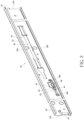
- a slide rail assembly 20 can be a multi-section rail assembly.
- the slide rail assembly 20 can be a four-section rail assembly.
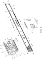
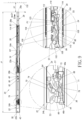
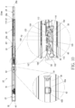
- the slide rail assembly 20 includes a supporting frame 22, a first rail 24, a second rail 26 and a third rail 28.
- the second rail 26 is movably mounted between the first rail 24 and the third rail 28.
- the first rail 24 can be an outer rail.
- the second rail 26 can be a middle rail.
- the third rail 28 can be an inner rail.
- the supporting frame 22 can be a fourth rail, which is used as a reinforced rail or a fixed rail.
- the supporting frame 22, the first rail 24, the second rail 26 and the third rail 28 can move relative to one another longitudinally.
- the slide rail assembly 20 When the slide rail assembly 20 is in an extended state, e.g., a fully extended state, the first rail 24 is located at a first predetermined position M1 relative to the supporting frame 22, the second rail 26 is located at a first extended position E1 relative to the first rail 24, and the third rail 28 is located at an opened position K relative to the second rail 26.
- the slide rail assembly can be a five-section rail assembly which includes an additional rail movably mounted on the supporting frame or the third rail.
- a longitudinal direction of the rail i.e., a length direction or a moving direction of rail
- a transverse direction of the rail i.e., a lateral direction of the rail
- a vertical direction of the rail i.e., a height direction of the rail, can be parallel to a Z axis.
- the supporting frame 22 includes a first wall 30a, a second wall 30b and a longitudinal wall 32 connected between the first wall 30a and the second wall 30b of the supporting frame 22.
- the first wall 30a, the second wall 30b and the longitudinal wall 32 of the supporting frame 22 cooperatively define a supporting channel 34 of the supporting frame 22.
- the supporting channel 34 is configured to at least partially accommodate the first rail 24.
- the supporting frame 22 further includes a front portion 22a and a rear portion 22b.
- a blocking structure 36 and a positioning structure 38 are arranged on the supporting frame 22.
- the positioning feature 38 can be formed in a column shape or a protrusion.
- the present invention is not limited thereto.
- the slide rail assembly 20 further includes a first working member 64 and a second working member 66.
- the first working member 64 is movably mounted on the first rail 24 and switchable between a first state S1 and a second state S2 relative to the first rail 24.
- the second working member 66 is movably mounted on the first rail 24 and switchable between a third state S3 and a fourth state S4 relative to the first rail 24.
- the first working member 64 and the second working member 66 can be respectively pivotally connected to the longitudinal wall 56 of the first rail 24 by a first pivoting member 68 and a second pivoting member 70 and located at the second side L2 of the first rail 24.
- the present invention is not limited to this embodiment.
- the slide rail assembly 20 further includes a first resilient member 72 and a second resilient member 74 respectively configured to provide resilient forces to the first working member 64 and the second working member 66 to drive the first working member 64 and the second working member 66 to move to the first state S 1 and the third state S3 relative to the first rail 24.
- the first rail 24 further includes a front restraining portion 80 and a rear restraining portion respectively configured to cooperate with the front restraining feature 40 and the rear restraining feature 42 of the supporting frame 22 for restraining a travel distance of the first rail 24 relative to the supporting frame 22.
- the front restraining portion 80 can be a protruding block located on the first side S 1 of the first rail 24 and facing toward the longitudinal wall 32 of the supporting frame 22, and the front restraining portion 80 can stretch into a longitudinal space 82 of the longitudinal wall 32 of the supporting frame 22, e.g., a longitudinal slot of the longitudinal wall 32 of the supporting frame 22, so as to be located at a position corresponding to the front restraining feature 40.
- the rear restraining portion can be the rear portion 24b.
- the present invention is not limited to this embodiment.
- the slide rail assembly 20 further includes a resilient seat 84 arranged on the first rail 24.
- the resilient seat 84 includes a first connecting portion 86a, a second connecting portion 86b and a supporting structure 88.
- the first connecting portion 86a and the second connecting portion 86b are connected to the longitudinal wall 56 of the first rail 24.
- the supporting structure 88 is located between the first connecting portion 86a and the second connecting portion 86b.
- the supporting structure 88 includes the blocking feature 60, a longitudinal portion 90 and a guiding portion 92.
- the longitudinal portion 90 is located between the blocking feature 60 and the guiding portion 92.
- the blocking feature 60 can be a blocking wall or an erecting wall
- the guiding portion 92 can be an inclined surface or an arc surface.
- the present invention is not limited thereto.
- the second rail 26 is movable relative to the first rail 24.
- the second rail 26 includes a first wall 94a, a second wall 94b and a longitudinal wall 96 connected between the first wall 94a and the second wall 94b of the second rail 26.
- the first wall 94a, the second wall 94b and the longitudinal wall 96 of the second rail 26 cooperatively define a second channel 98 of the second rail 26.
- the second channel 98 is configured to at least partially accommodate the third rail 28.
- the second rail 26 further includes a front portion 26a and a rear portion 26b.
- the second rail 26 further includes a first side L1 and a second side L2 opposite to the first side L 1.
- the first side L1 of the second rail 26 is located adjacent to the first rail 24.
- the second side L2 of the second rail 26 is located adjacent to the third rail 28.
- the second rail 26 further includes at least one hole arranged on the longitudinal wall 96 of the second rail 26 and communicated with the first side L1 and the second side L2 of the second rail 26.
- the second rail 26 can include a first hole H1 and a second hole H2.
- the third working member 100 includes a first blocking section 108 stretching into the first hole H1.
- the first blocking section 108 faces toward the longitudinal wall 56 of the first rail 24 and is configured to cooperate with the blocking feature 60 or the positioning feature 62 of the first rail 24.
- the fourth working member 102 includes a second blocking section 110 stretching into the second hole H2.
- the second blocking section 110 faces toward the longitudinal wall 56 of the first rail 24 and is configured to cooperate with the positioning feature 62 of the first rail 24.
- the present invention is not limited to this embodiment.
- the slide rail assembly 20 further includes an operating member 112 movably mounted on the second rail 26 and configured to operate one of the third working member 100 and the fourth working member 102.
- the operating member 112 is mounted on the longitudinal wall 96 of the second rail 26 and located at the first side L1 of the second rail 26.
- the operating member 112 includes an operating portion 114, a driving portion 116 and an extending portion 118 connected between the operating portion 114 and the driving portion 116.
- the operating portion 114 is connected to a front end 118a of the extending portion 118.
- the operating portion 114 is located adjacent to the front portion 26a of the second rail 26.
- the driving portion 116 is connected to a rear end 118b of the extending portion 118.
- the driving portion 116 is located adjacent to the rear portion 26b of the second rail 26.
- the third working member 100 and the fourth working member 102 are located adjacent to the rear portion 26b of the second rail 26.
- the second rail 26 further includes a third hole H3 arranged on the longitudinal wall 96 of the second rail 26.
- the driving portion 116 of the operating member 112 extends from the first side L1 to the second side L2 of the second rail 26 through the third hole H3 and is located adjacent to the third working member 100.
- the second rail 26 further includes a fourth hole H4 arranged on the longitudinal wall 96 of the second rail 26.
- the operating portion 114 of the operating member 112 is exposed on the second side L2 of the second rail 26 via the fourth hole H4.
- the second rail 26 and the operating member 112 have corresponding restraining features cooperating with each other for restraining a travel distance of the operating member 112 relative to the second rail 26.
- at least one elongated hole 120 can be arranged on the extending portion 118 of the operating member 112.
- the second rail 26 can further include at least one connecting member 122 connected to the longitudinal wall 96 of the second rail 26 and passing through a portion of the at least one elongated hole 120.
- the second rail 26 can further include at least one extending hole 111.
- At least one connecting section 113 can be arranged on the extending portion 118 of the operating member 112 and passes through a portion of the at least one extending hole 111.
- the travel distance of the operating member 112 relative to the second rail 26 can be restrained by a cooperation of the at least one elongated hole 120 and the at least one connecting member 122 and a cooperation of the at least one extending hole 111 and the at least one connecting section 113.
- the present invention is not limited to this embodiment.
- the third working member 100 further includes an abutting portion 124 and an actuating portion 126.
- the first shaft 104 is located between the abutting portion 124 and the actuating portion 126.
- the abutting portion 124 is located at a position corresponding to the driving portion 116 of the operating member 112 and for abutting against the driving portion 116 of the operating member 112.
- the first blocking section 108 is located adjacent to the actuating portion 126.
- the first blocking section 108 extends to the first side L1 of the second rail 26.
- the first resilient feature 105 is configured to provide the resilient force to the third working member 100 for retaining the third working member 100 in the fifth state S5.
- the fourth working member 102 includes an abutting section 128 and an actuating section 130.
- the second shaft 106 is located between the abutting section 128 and the actuating section 130.
- the second blocking section 110 is located adjacent to the abutting section 128.
- the second blocking section 110 extends to the first side L1 of the second rail 26.
- the second resilient feature 107 is configured to provide the resilient force to the fourth working member 102 for retaining the fourth working member 102 in the seventh state S7.
- the third working member and the fourth working member are configured to move synchronously, and the third working member and the fourth working member are respectively configured to be driven by the fourth working member and the operating member.
- the third working member and the fourth working member are configured to move synchronously, and the third working member and the fourth working member are configured to be driven by two driving portions of the operating member respectively.
- the slide rail assembly further includes an auxiliary operating member, and the third working member and the fourth working member are configured to be driven by the operating member and the auxiliary operating member respectively and to move asynchronously.
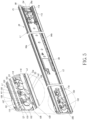
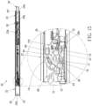
- the blocking feature 60 of the first rail 24 blocks the first blocking section 108 of the third working member 100 in the fifth state S5 for preventing the second rail 26 from moving along the retracting direction D2 from the first extended position E1, and the second blocking section 110 of the fourth working member 102 is located adjacent to the guiding portion 92 of the resilient seat 84 of the first rail 24.
- the first blocking section 108 of the third working member 100 and the second blocking section 110 of the fourth working member 102 are located at positions where the first blocking section 108 of the third working member 100 and the second blocking section 110 of the fourth working member 102 are aligned with the positioning feature 62 of the first rail 24 along the retracting direction D2 or the opening direction D 1.
- the operating member 112 drives the third working member 100 by the driving portion 116 to move from the fifth state S5 to the sixth state S6, such that the blocking feature 60 cannot block the first blocking section 108 of the third working member 100 in the sixth state S6 for allowing the second rail 26 to move relative to the first rail 24 along the retracting direction D2 from the first extended position E1.
- the third working member 100 and the fourth working member 102 are respectively retained in the sixth state S6 and the eighth state S8, such that the first resilient feature 105 and the second resilient feature 107 are resiliently deformed to generate the resilient forces, similarly to FIG. 7 .
- One of the first blocking section 108 of the third working member 100 and the rear portion 62b of the positioning feature 62 includes a guiding feature 109.
- the guiding feature 109 can be an inclined surface or an arc surface.
- the first blocking section 108 can include the guiding feature 109.
- the present invention is not limited to this embodiment.
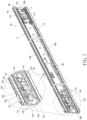
- the third working member 100 drives the fourth working member 102 to move from the seventh state S7 to the eighth state S8, such that the first resilient feature 105 and the second resilient feature 107 are resiliently deformed and generate the resilient forces. Therefore, the first resilient feature 105 and the second resilient feature 107 respectively can drive the third working member 100 and the fourth working member 102 to move to the fifth state S5 and the seventh state S7 when the second rail 26 moves to the second extended position E2 relative to the first rail 24. Besides, when the second rail 26 is located at the second extended position E2 as shown in FIG.
- the second blocking section 110 of the fourth working member 102 in the seventh state S7 and the first blocking section 108 of the third working member 100 in the fifth state S5 are respectively located at positions corresponding to the two portions of the positioning feature 62, e.g., the rear portion 62b and the front portion 62a, so as to provide a blocking effect or an engaging effect for preventing the second rail 26 from moving relative to the first rail 24 along the opening direction D1 or the retracting direction D2 from the second extended position E2.
- the slide rail assembly 20 has a second length J2 less than the first length 11, such that the front portion 28a of the third rail 28 is spaced apart from the object 132 by a second distance X2 greater than the first distance X1, which facilitates detachment of the third rail 28 from the second rail 26, e.g., the second channel 98 of the second rail 26, along the opening direction D1.
- the third working member 100 and the fourth working member 102 move to the sixth state S6 and the eighth state S8 respectively, the third working member 100 and the fourth working member 102 are respectively dislocated from the positions corresponding to the two portions of the positioning feature 62, e.g., the rear portion 62b and the front portion 62a, for allowing the second rail 26 to move relative to the first rail 24 along the opening direction D1 or the retracting direction D2 from the second extended position E2.
- the second working member 66 e.g., the positioning portion 73 of the second working member 66, in the third state S3 can engage with the positioning structure 38 of the supporting frame 22 for retaining the first rail 24 at the second predetermined position M2, so as to prevent the first rail 24 from moving along the opening direction D1 or the retracting direction D2 from the second predetermined position M2.
- the third rail 28 further includes a first synchronizing feature 136 and a second synchronizing feature 138.
- the first synchronizing feature 136 of the third rail 28 can abut against a first corresponding feature 140 of the first working member 64 for driving the third rail 28 and the first rail 24 to move synchronously along the opening direction D1 until the first rail 24 moves to the first predetermined position M1.
Landscapes
- Engineering & Computer Science (AREA)
- General Engineering & Computer Science (AREA)
- Mechanical Engineering (AREA)
- Computer Hardware Design (AREA)
- Microelectronics & Electronic Packaging (AREA)
- Seats For Vehicles (AREA)
- Drawers Of Furniture (AREA)
- Bearings For Parts Moving Linearly (AREA)
Applications Claiming Priority (1)
| Application Number | Priority Date | Filing Date | Title |
|---|---|---|---|
| TW111150803A TWI861654B (zh) | 2022-12-28 | 2022-12-28 | 滑軌總成 |
Publications (2)
| Publication Number | Publication Date |
|---|---|
| EP4393348A1 true EP4393348A1 (de) | 2024-07-03 |
| EP4393348B1 EP4393348B1 (de) | 2025-05-21 |
Family
ID=86732701
Family Applications (1)
| Application Number | Title | Priority Date | Filing Date |
|---|---|---|---|
| EP23178095.8A Active EP4393348B1 (de) | 2022-12-28 | 2023-06-07 | Gleitschienenanordnung |
Country Status (4)
| Country | Link |
|---|---|
| US (1) | US12127671B2 (de) |
| EP (1) | EP4393348B1 (de) |
| JP (1) | JP7450787B1 (de) |
| TW (1) | TWI861654B (de) |
Families Citing this family (1)
| Publication number | Priority date | Publication date | Assignee | Title |
|---|---|---|---|---|
| TWI856904B (zh) * | 2023-12-25 | 2024-09-21 | 川湖科技股份有限公司 | 滑軌總成 |
Citations (3)
| Publication number | Priority date | Publication date | Assignee | Title |
|---|---|---|---|---|
| US20130259410A1 (en) * | 2012-04-03 | 2013-10-03 | Jonathan Manufacturing Corporation Dba Jonathan Engineered Solutions | Compact slide assemblies |
| US10791833B2 (en) * | 2018-11-23 | 2020-10-06 | King Slide Works Co., Ltd. | Slide rail assembly |
| US20220240673A1 (en) | 2021-02-01 | 2022-08-04 | King Slide Works Co., Ltd. | Slide rail assembly |
Family Cites Families (19)
| Publication number | Priority date | Publication date | Assignee | Title |
|---|---|---|---|---|
| TWI568382B (zh) * | 2016-01-22 | 2017-02-01 | 川湖科技股份有限公司 | 滑軌總成及其操作方法 |
| CN107960763B (zh) * | 2016-10-18 | 2020-01-14 | 川湖科技股份有限公司 | 滑轨总成 |
| TWI629027B (zh) * | 2017-03-20 | 2018-07-11 | 川湖科技股份有限公司 | 用於滑軌總成的同步系統 |
| TWI665983B (zh) | 2017-04-12 | 2019-07-21 | 川湖科技股份有限公司 | 滑軌總成 |
| TWI616166B (zh) * | 2017-04-12 | 2018-03-01 | 川湖科技股份有限公司 | 滑軌總成 |
| CN108720377B (zh) * | 2017-04-19 | 2019-08-27 | 川湖科技股份有限公司 | 滑轨总成 |
| US10674821B2 (en) * | 2017-12-28 | 2020-06-09 | King Slide Works Co., Ltd | Slide rail assembly |
| CN110392503B (zh) | 2018-04-16 | 2020-11-03 | 鸿富锦精密电子(天津)有限公司 | 滑轨装置 |
| TWI687178B (zh) * | 2018-05-07 | 2020-03-11 | 川湖科技股份有限公司 | 滑軌總成及其滑軌套件 |
| TWI684396B (zh) | 2019-02-25 | 2020-02-01 | 川湖科技股份有限公司 | 滑軌機構及其支撐總成 |
| TWI700057B (zh) * | 2019-06-12 | 2020-08-01 | 川湖科技股份有限公司 | 滑軌總成及其操作方法 |
| CN112089231B (zh) | 2019-06-17 | 2022-08-12 | 川湖科技股份有限公司 | 滑轨总成及其操作方法 |
| TWI704888B (zh) * | 2019-07-12 | 2020-09-21 | 川湖科技股份有限公司 | 滑軌總成 |
| TWI706751B (zh) | 2019-08-14 | 2020-10-11 | 川湖科技股份有限公司 | 滑軌總成 |
| TWI704887B (zh) | 2019-09-26 | 2020-09-21 | 川湖科技股份有限公司 | 滑軌總成 |
| TWI704889B (zh) * | 2019-10-28 | 2020-09-21 | 川湖科技股份有限公司 | 滑軌總成 |
| CN112971407B (zh) * | 2019-12-18 | 2023-09-22 | 川湖科技股份有限公司 | 滑轨总成 |
| TWI733625B (zh) | 2020-11-24 | 2021-07-11 | 川湖科技股份有限公司 | 滑軌總成 |
| TWI737555B (zh) | 2020-12-22 | 2021-08-21 | 川湖科技股份有限公司 | 滑軌總成及其滑軌套件 |
-
2022
- 2022-12-28 TW TW111150803A patent/TWI861654B/zh active
-
2023
- 2023-05-16 US US18/197,733 patent/US12127671B2/en active Active
- 2023-06-07 EP EP23178095.8A patent/EP4393348B1/de active Active
- 2023-06-19 JP JP2023100222A patent/JP7450787B1/ja active Active
Patent Citations (3)
| Publication number | Priority date | Publication date | Assignee | Title |
|---|---|---|---|---|
| US20130259410A1 (en) * | 2012-04-03 | 2013-10-03 | Jonathan Manufacturing Corporation Dba Jonathan Engineered Solutions | Compact slide assemblies |
| US10791833B2 (en) * | 2018-11-23 | 2020-10-06 | King Slide Works Co., Ltd. | Slide rail assembly |
| US20220240673A1 (en) | 2021-02-01 | 2022-08-04 | King Slide Works Co., Ltd. | Slide rail assembly |
Also Published As
| Publication number | Publication date |
|---|---|
| TWI861654B (zh) | 2024-11-11 |
| EP4393348B1 (de) | 2025-05-21 |
| US20240215720A1 (en) | 2024-07-04 |
| JP2024095497A (ja) | 2024-07-10 |
| JP7450787B1 (ja) | 2024-03-15 |
| US12127671B2 (en) | 2024-10-29 |
| TW202425879A (zh) | 2024-07-01 |
Similar Documents
| Publication | Publication Date | Title |
|---|---|---|
| EP4393349A1 (de) | Gleitschienenanordnung | |
| EP4393348A1 (de) | Gleitschienenanordnung | |
| EP4501174B1 (de) | Gleitschienenanordnung | |
| JP2002211497A (ja) | 降下可能な荷物室を備えた荷物棚、特に飛行機の客室用の荷物棚 | |
| EP4477823A1 (de) | Verriegelungskit und zugehörige möbelanordnung | |
| US12203292B2 (en) | Slide rail mechanism | |
| JP7800927B2 (ja) | スライドレール機構 | |
| JP7471494B1 (ja) | スライドレール機構 | |
| EP4631393B1 (de) | Gleitschienenanordnung | |
| EP4461160B1 (de) | Möbelanordnung | |
| EP4420560A1 (de) | Gleitschienenmechanismus | |
| CN116696166B (zh) | 一种车门锁闭机构、车门及铁路保温车 | |
| EP3561208A1 (de) | Türöffnungsvorrichtung, insbesondere für öffentliche verkehrsmittel | |
| US7581777B2 (en) | Header latch assembly for convertible tops | |
| EP4736711A1 (de) | Gleitschienenanordnung | |
| EP4648558A1 (de) | Gestellmontagekit | |
| EP4581983B1 (de) | Gleitschienenmechanismus | |
| EP4616761B1 (de) | Gleitschienenmechanismus | |
| EP4480344B1 (de) | Gleitschienenanordnung | |
| CN220564227U (zh) | 用于搬运电控单元的操纵设备 | |
| CN112848029B (zh) | 一种往返移动式模架开合机械手 | |
| CN120119838A (zh) | 一种抗冲击闭锁 | |
| JPH09254618A (ja) | 車輌連結幌装置 | |
| CN118274029A (zh) | 滑轨总成 | |
| CN121755833A (zh) | 夹具定位结构及夹具 |
Legal Events
| Date | Code | Title | Description |
|---|---|---|---|
| PUAI | Public reference made under article 153(3) epc to a published international application that has entered the european phase |
Free format text: ORIGINAL CODE: 0009012 |
|
| STAA | Information on the status of an ep patent application or granted ep patent |
Free format text: STATUS: THE APPLICATION HAS BEEN PUBLISHED |
|
| STAA | Information on the status of an ep patent application or granted ep patent |
Free format text: STATUS: REQUEST FOR EXAMINATION WAS MADE |
|
| AK | Designated contracting states |
Kind code of ref document: A1 Designated state(s): AL AT BE BG CH CY CZ DE DK EE ES FI FR GB GR HR HU IE IS IT LI LT LU LV MC ME MK MT NL NO PL PT RO RS SE SI SK SM TR |
|
| 17P | Request for examination filed |
Effective date: 20240604 |
|
| RBV | Designated contracting states (corrected) |
Designated state(s): AL AT BE BG CH CY CZ DE DK EE ES FI FR GB GR HR HU IE IS IT LI LT LU LV MC ME MK MT NL NO PL PT RO RS SE SI SK SM TR |
|
| GRAP | Despatch of communication of intention to grant a patent |
Free format text: ORIGINAL CODE: EPIDOSNIGR1 |
|
| STAA | Information on the status of an ep patent application or granted ep patent |
Free format text: STATUS: GRANT OF PATENT IS INTENDED |
|
| INTG | Intention to grant announced |
Effective date: 20250127 |
|
| GRAS | Grant fee paid |
Free format text: ORIGINAL CODE: EPIDOSNIGR3 |
|
| GRAA | (expected) grant |
Free format text: ORIGINAL CODE: 0009210 |
|
| STAA | Information on the status of an ep patent application or granted ep patent |
Free format text: STATUS: THE PATENT HAS BEEN GRANTED |
|
| AK | Designated contracting states |
Kind code of ref document: B1 Designated state(s): AL AT BE BG CH CY CZ DE DK EE ES FI FR GB GR HR HU IE IS IT LI LT LU LV MC ME MK MT NL NO PL PT RO RS SE SI SK SM TR |
|
| REG | Reference to a national code |
Ref country code: GB Ref legal event code: FG4D |
|
| REG | Reference to a national code |
Ref country code: CH Ref legal event code: EP |
|
| REG | Reference to a national code |
Ref country code: DE Ref legal event code: R096 Ref document number: 602023003571 Country of ref document: DE |
|
| REG | Reference to a national code |
Ref country code: IE Ref legal event code: FG4D |
|
| PGFP | Annual fee paid to national office [announced via postgrant information from national office to epo] |
Ref country code: DE Payment date: 20250526 Year of fee payment: 3 |
|
| PGFP | Annual fee paid to national office [announced via postgrant information from national office to epo] |
Ref country code: AT Payment date: 20250721 Year of fee payment: 3 |
|
| REG | Reference to a national code |
Ref country code: NL Ref legal event code: MP Effective date: 20250521 |
|
| PG25 | Lapsed in a contracting state [announced via postgrant information from national office to epo] |
Ref country code: FI Free format text: LAPSE BECAUSE OF FAILURE TO SUBMIT A TRANSLATION OF THE DESCRIPTION OR TO PAY THE FEE WITHIN THE PRESCRIBED TIME-LIMIT Effective date: 20250521 Ref country code: ES Free format text: LAPSE BECAUSE OF FAILURE TO SUBMIT A TRANSLATION OF THE DESCRIPTION OR TO PAY THE FEE WITHIN THE PRESCRIBED TIME-LIMIT Effective date: 20250521 Ref country code: PT Free format text: LAPSE BECAUSE OF FAILURE TO SUBMIT A TRANSLATION OF THE DESCRIPTION OR TO PAY THE FEE WITHIN THE PRESCRIBED TIME-LIMIT Effective date: 20250922 |
|
| REG | Reference to a national code |
Ref country code: LT Ref legal event code: MG9D |
|
| PG25 | Lapsed in a contracting state [announced via postgrant information from national office to epo] |
Ref country code: NO Free format text: LAPSE BECAUSE OF FAILURE TO SUBMIT A TRANSLATION OF THE DESCRIPTION OR TO PAY THE FEE WITHIN THE PRESCRIBED TIME-LIMIT Effective date: 20250821 Ref country code: GR Free format text: LAPSE BECAUSE OF FAILURE TO SUBMIT A TRANSLATION OF THE DESCRIPTION OR TO PAY THE FEE WITHIN THE PRESCRIBED TIME-LIMIT Effective date: 20250822 |
|
| PG25 | Lapsed in a contracting state [announced via postgrant information from national office to epo] |
Ref country code: PL Free format text: LAPSE BECAUSE OF FAILURE TO SUBMIT A TRANSLATION OF THE DESCRIPTION OR TO PAY THE FEE WITHIN THE PRESCRIBED TIME-LIMIT Effective date: 20250521 Ref country code: NL Free format text: LAPSE BECAUSE OF FAILURE TO SUBMIT A TRANSLATION OF THE DESCRIPTION OR TO PAY THE FEE WITHIN THE PRESCRIBED TIME-LIMIT Effective date: 20250521 |
|
| PG25 | Lapsed in a contracting state [announced via postgrant information from national office to epo] |
Ref country code: BG Free format text: LAPSE BECAUSE OF FAILURE TO SUBMIT A TRANSLATION OF THE DESCRIPTION OR TO PAY THE FEE WITHIN THE PRESCRIBED TIME-LIMIT Effective date: 20250521 |
|
| PG25 | Lapsed in a contracting state [announced via postgrant information from national office to epo] |
Ref country code: HR Free format text: LAPSE BECAUSE OF FAILURE TO SUBMIT A TRANSLATION OF THE DESCRIPTION OR TO PAY THE FEE WITHIN THE PRESCRIBED TIME-LIMIT Effective date: 20250521 |
|
| PG25 | Lapsed in a contracting state [announced via postgrant information from national office to epo] |
Ref country code: RS Free format text: LAPSE BECAUSE OF FAILURE TO SUBMIT A TRANSLATION OF THE DESCRIPTION OR TO PAY THE FEE WITHIN THE PRESCRIBED TIME-LIMIT Effective date: 20250821 |
|
| PGFP | Annual fee paid to national office [announced via postgrant information from national office to epo] |
Ref country code: IE Payment date: 20250704 Year of fee payment: 3 |
|
| PG25 | Lapsed in a contracting state [announced via postgrant information from national office to epo] |
Ref country code: IS Free format text: LAPSE BECAUSE OF FAILURE TO SUBMIT A TRANSLATION OF THE DESCRIPTION OR TO PAY THE FEE WITHIN THE PRESCRIBED TIME-LIMIT Effective date: 20250921 |
|
| PG25 | Lapsed in a contracting state [announced via postgrant information from national office to epo] |
Ref country code: LV Free format text: LAPSE BECAUSE OF FAILURE TO SUBMIT A TRANSLATION OF THE DESCRIPTION OR TO PAY THE FEE WITHIN THE PRESCRIBED TIME-LIMIT Effective date: 20250521 |
|
| REG | Reference to a national code |
Ref country code: AT Ref legal event code: MK05 Ref document number: 1796019 Country of ref document: AT Kind code of ref document: T Effective date: 20250521 |
|
| PG25 | Lapsed in a contracting state [announced via postgrant information from national office to epo] |
Ref country code: DK Free format text: LAPSE BECAUSE OF FAILURE TO SUBMIT A TRANSLATION OF THE DESCRIPTION OR TO PAY THE FEE WITHIN THE PRESCRIBED TIME-LIMIT Effective date: 20250521 Ref country code: AT Free format text: LAPSE BECAUSE OF FAILURE TO SUBMIT A TRANSLATION OF THE DESCRIPTION OR TO PAY THE FEE WITHIN THE PRESCRIBED TIME-LIMIT Effective date: 20250521 Ref country code: SM Free format text: LAPSE BECAUSE OF FAILURE TO SUBMIT A TRANSLATION OF THE DESCRIPTION OR TO PAY THE FEE WITHIN THE PRESCRIBED TIME-LIMIT Effective date: 20250521 |
|
| PG25 | Lapsed in a contracting state [announced via postgrant information from national office to epo] |
Ref country code: CZ Free format text: LAPSE BECAUSE OF FAILURE TO SUBMIT A TRANSLATION OF THE DESCRIPTION OR TO PAY THE FEE WITHIN THE PRESCRIBED TIME-LIMIT Effective date: 20250521 |
|
| PG25 | Lapsed in a contracting state [announced via postgrant information from national office to epo] |
Ref country code: EE Free format text: LAPSE BECAUSE OF FAILURE TO SUBMIT A TRANSLATION OF THE DESCRIPTION OR TO PAY THE FEE WITHIN THE PRESCRIBED TIME-LIMIT Effective date: 20250521 |
|
| PG25 | Lapsed in a contracting state [announced via postgrant information from national office to epo] |
Ref country code: SK Free format text: LAPSE BECAUSE OF FAILURE TO SUBMIT A TRANSLATION OF THE DESCRIPTION OR TO PAY THE FEE WITHIN THE PRESCRIBED TIME-LIMIT Effective date: 20250521 |
|
| PG25 | Lapsed in a contracting state [announced via postgrant information from national office to epo] |
Ref country code: IT Free format text: LAPSE BECAUSE OF FAILURE TO SUBMIT A TRANSLATION OF THE DESCRIPTION OR TO PAY THE FEE WITHIN THE PRESCRIBED TIME-LIMIT Effective date: 20250521 |
|
| PG25 | Lapsed in a contracting state [announced via postgrant information from national office to epo] |
Ref country code: LU Free format text: LAPSE BECAUSE OF NON-PAYMENT OF DUE FEES Effective date: 20250607 |
|
| PG25 | Lapsed in a contracting state [announced via postgrant information from national office to epo] |
Ref country code: MC Free format text: LAPSE BECAUSE OF FAILURE TO SUBMIT A TRANSLATION OF THE DESCRIPTION OR TO PAY THE FEE WITHIN THE PRESCRIBED TIME-LIMIT Effective date: 20250521 |
|
| REG | Reference to a national code |
Ref country code: DE Ref legal event code: R097 Ref document number: 602023003571 Country of ref document: DE |
|
| REG | Reference to a national code |
Ref country code: BE Ref legal event code: MM Effective date: 20250630 |
|
| PG25 | Lapsed in a contracting state [announced via postgrant information from national office to epo] |
Ref country code: RO Free format text: LAPSE BECAUSE OF FAILURE TO SUBMIT A TRANSLATION OF THE DESCRIPTION OR TO PAY THE FEE WITHIN THE PRESCRIBED TIME-LIMIT Effective date: 20250521 |
|
| PLBE | No opposition filed within time limit |
Free format text: ORIGINAL CODE: 0009261 |
|
| STAA | Information on the status of an ep patent application or granted ep patent |
Free format text: STATUS: NO OPPOSITION FILED WITHIN TIME LIMIT |
|
| REG | Reference to a national code |
Ref country code: CH Ref legal event code: L10 Free format text: ST27 STATUS EVENT CODE: U-0-0-L10-L00 (AS PROVIDED BY THE NATIONAL OFFICE) Effective date: 20260402 |
|
| PG25 | Lapsed in a contracting state [announced via postgrant information from national office to epo] |
Ref country code: BE Free format text: LAPSE BECAUSE OF NON-PAYMENT OF DUE FEES Effective date: 20250630 |
|
| PG25 | Lapsed in a contracting state [announced via postgrant information from national office to epo] |
Ref country code: FR Free format text: LAPSE BECAUSE OF NON-PAYMENT OF DUE FEES Effective date: 20250721 |
|
| 26N | No opposition filed |
Effective date: 20260224 |