EP4393376A1 - Multimodale gehirnfunktionssignalerfassungsvorrichtung und verfahren - Google Patents
Multimodale gehirnfunktionssignalerfassungsvorrichtung und verfahren Download PDFInfo
- Publication number
- EP4393376A1 EP4393376A1 EP23208600.9A EP23208600A EP4393376A1 EP 4393376 A1 EP4393376 A1 EP 4393376A1 EP 23208600 A EP23208600 A EP 23208600A EP 4393376 A1 EP4393376 A1 EP 4393376A1
- Authority
- EP
- European Patent Office
- Prior art keywords
- signal
- resistor
- amplifier
- eeg
- acquisition device
- Prior art date
- Legal status (The legal status is an assumption and is not a legal conclusion. Google has not performed a legal analysis and makes no representation as to the accuracy of the status listed.)
- Granted
Links
Images


Classifications
-
- A—HUMAN NECESSITIES
- A61—MEDICAL OR VETERINARY SCIENCE; HYGIENE
- A61B—DIAGNOSIS; SURGERY; IDENTIFICATION
- A61B5/00—Measuring for diagnostic purposes; Identification of persons
- A61B5/24—Detecting, measuring or recording bioelectric or biomagnetic signals of the body or parts thereof
- A61B5/316—Modalities, i.e. specific diagnostic methods
- A61B5/369—Electroencephalography [EEG]
- A61B5/384—Recording apparatus or displays specially adapted therefor
-
- A—HUMAN NECESSITIES
- A61—MEDICAL OR VETERINARY SCIENCE; HYGIENE
- A61B—DIAGNOSIS; SURGERY; IDENTIFICATION
- A61B5/00—Measuring for diagnostic purposes; Identification of persons
- A61B5/0059—Measuring for diagnostic purposes; Identification of persons using light, e.g. diagnosis by transillumination, diascopy, fluorescence
- A61B5/0075—Measuring for diagnostic purposes; Identification of persons using light, e.g. diagnosis by transillumination, diascopy, fluorescence by spectroscopy, i.e. measuring spectra, e.g. Raman spectroscopy, infrared absorption spectroscopy
-
- A—HUMAN NECESSITIES
- A61—MEDICAL OR VETERINARY SCIENCE; HYGIENE
- A61B—DIAGNOSIS; SURGERY; IDENTIFICATION
- A61B5/00—Measuring for diagnostic purposes; Identification of persons
- A61B5/0059—Measuring for diagnostic purposes; Identification of persons using light, e.g. diagnosis by transillumination, diascopy, fluorescence
- A61B5/0082—Measuring for diagnostic purposes; Identification of persons using light, e.g. diagnosis by transillumination, diascopy, fluorescence adapted for particular medical purposes
-
- A—HUMAN NECESSITIES
- A61—MEDICAL OR VETERINARY SCIENCE; HYGIENE
- A61B—DIAGNOSIS; SURGERY; IDENTIFICATION
- A61B5/00—Measuring for diagnostic purposes; Identification of persons
- A61B5/145—Measuring characteristics of blood in vivo, e.g. gas concentration or pH-value ; Measuring characteristics of body fluids or tissues, e.g. interstitial fluid or cerebral tissue
- A61B5/1455—Measuring characteristics of blood in vivo, e.g. gas concentration or pH-value ; Measuring characteristics of body fluids or tissues, e.g. interstitial fluid or cerebral tissue using optical sensors, e.g. spectral photometrical oximeters
- A61B5/14551—Measuring characteristics of blood in vivo, e.g. gas concentration or pH-value ; Measuring characteristics of body fluids or tissues, e.g. interstitial fluid or cerebral tissue using optical sensors, e.g. spectral photometrical oximeters for measuring blood gases
- A61B5/14553—Measuring characteristics of blood in vivo, e.g. gas concentration or pH-value ; Measuring characteristics of body fluids or tissues, e.g. interstitial fluid or cerebral tissue using optical sensors, e.g. spectral photometrical oximeters for measuring blood gases specially adapted for cerebral tissue
-
- A—HUMAN NECESSITIES
- A61—MEDICAL OR VETERINARY SCIENCE; HYGIENE
- A61B—DIAGNOSIS; SURGERY; IDENTIFICATION
- A61B5/00—Measuring for diagnostic purposes; Identification of persons
- A61B5/24—Detecting, measuring or recording bioelectric or biomagnetic signals of the body or parts thereof
- A61B5/25—Bioelectric electrodes therefor
- A61B5/251—Means for maintaining electrode contact with the body
- A61B5/256—Wearable electrodes, e.g. having straps or bands
-
- A—HUMAN NECESSITIES
- A61—MEDICAL OR VETERINARY SCIENCE; HYGIENE
- A61B—DIAGNOSIS; SURGERY; IDENTIFICATION
- A61B5/00—Measuring for diagnostic purposes; Identification of persons
- A61B5/24—Detecting, measuring or recording bioelectric or biomagnetic signals of the body or parts thereof
- A61B5/25—Bioelectric electrodes therefor
- A61B5/251—Means for maintaining electrode contact with the body
- A61B5/257—Means for maintaining electrode contact with the body using adhesive means, e.g. adhesive pads or tapes
- A61B5/259—Means for maintaining electrode contact with the body using adhesive means, e.g. adhesive pads or tapes using conductive adhesive means, e.g. gels
-
- A—HUMAN NECESSITIES
- A61—MEDICAL OR VETERINARY SCIENCE; HYGIENE
- A61B—DIAGNOSIS; SURGERY; IDENTIFICATION
- A61B5/00—Measuring for diagnostic purposes; Identification of persons
- A61B5/24—Detecting, measuring or recording bioelectric or biomagnetic signals of the body or parts thereof
- A61B5/25—Bioelectric electrodes therefor
- A61B5/263—Bioelectric electrodes therefor characterised by the electrode materials
- A61B5/265—Bioelectric electrodes therefor characterised by the electrode materials containing silver or silver chloride
-
- A—HUMAN NECESSITIES
- A61—MEDICAL OR VETERINARY SCIENCE; HYGIENE
- A61B—DIAGNOSIS; SURGERY; IDENTIFICATION
- A61B5/00—Measuring for diagnostic purposes; Identification of persons
- A61B5/24—Detecting, measuring or recording bioelectric or biomagnetic signals of the body or parts thereof
- A61B5/25—Bioelectric electrodes therefor
- A61B5/279—Bioelectric electrodes therefor specially adapted for particular uses
- A61B5/291—Bioelectric electrodes therefor specially adapted for particular uses for electroencephalography [EEG]
-
- A—HUMAN NECESSITIES
- A61—MEDICAL OR VETERINARY SCIENCE; HYGIENE
- A61B—DIAGNOSIS; SURGERY; IDENTIFICATION
- A61B5/00—Measuring for diagnostic purposes; Identification of persons
- A61B5/24—Detecting, measuring or recording bioelectric or biomagnetic signals of the body or parts thereof
- A61B5/30—Input circuits therefor
- A61B5/307—Input circuits therefor specially adapted for particular uses
- A61B5/31—Input circuits therefor specially adapted for particular uses for electroencephalography [EEG]
-
- A—HUMAN NECESSITIES
- A61—MEDICAL OR VETERINARY SCIENCE; HYGIENE
- A61B—DIAGNOSIS; SURGERY; IDENTIFICATION
- A61B5/00—Measuring for diagnostic purposes; Identification of persons
- A61B5/40—Detecting, measuring or recording for evaluating the nervous system
- A61B5/4058—Detecting, measuring or recording for evaluating the nervous system for evaluating the central nervous system
- A61B5/4064—Evaluating the brain
-
- A—HUMAN NECESSITIES
- A61—MEDICAL OR VETERINARY SCIENCE; HYGIENE
- A61B—DIAGNOSIS; SURGERY; IDENTIFICATION
- A61B5/00—Measuring for diagnostic purposes; Identification of persons
- A61B5/68—Arrangements of detecting, measuring or recording means, e.g. sensors, in relation to patient
- A61B5/6801—Arrangements of detecting, measuring or recording means, e.g. sensors, in relation to patient specially adapted to be attached to or worn on the body surface
- A61B5/6802—Sensor mounted on worn items
- A61B5/6803—Head-worn items, e.g. helmets, masks, headphones or goggles
-
- A—HUMAN NECESSITIES
- A61—MEDICAL OR VETERINARY SCIENCE; HYGIENE
- A61B—DIAGNOSIS; SURGERY; IDENTIFICATION
- A61B5/00—Measuring for diagnostic purposes; Identification of persons
- A61B5/68—Arrangements of detecting, measuring or recording means, e.g. sensors, in relation to patient
- A61B5/6801—Arrangements of detecting, measuring or recording means, e.g. sensors, in relation to patient specially adapted to be attached to or worn on the body surface
- A61B5/6813—Specially adapted to be attached to a specific body part
- A61B5/6814—Head
-
- A—HUMAN NECESSITIES
- A61—MEDICAL OR VETERINARY SCIENCE; HYGIENE
- A61B—DIAGNOSIS; SURGERY; IDENTIFICATION
- A61B5/00—Measuring for diagnostic purposes; Identification of persons
- A61B5/72—Signal processing specially adapted for physiological signals or for diagnostic purposes
- A61B5/7225—Details of analogue processing, e.g. isolation amplifier, gain or sensitivity adjustment, filtering, baseline or drift compensation
-
- A—HUMAN NECESSITIES
- A61—MEDICAL OR VETERINARY SCIENCE; HYGIENE
- A61B—DIAGNOSIS; SURGERY; IDENTIFICATION
- A61B5/00—Measuring for diagnostic purposes; Identification of persons
- A61B5/72—Signal processing specially adapted for physiological signals or for diagnostic purposes
- A61B5/7271—Specific aspects of physiological measurement analysis
-
- A—HUMAN NECESSITIES
- A61—MEDICAL OR VETERINARY SCIENCE; HYGIENE
- A61B—DIAGNOSIS; SURGERY; IDENTIFICATION
- A61B2560/00—Constructional details of operational features of apparatus; Accessories for medical measuring apparatus
- A61B2560/02—Operational features
-
- A—HUMAN NECESSITIES
- A61—MEDICAL OR VETERINARY SCIENCE; HYGIENE
- A61B—DIAGNOSIS; SURGERY; IDENTIFICATION
- A61B2560/00—Constructional details of operational features of apparatus; Accessories for medical measuring apparatus
- A61B2560/04—Constructional details of apparatus
- A61B2560/0462—Apparatus with built-in sensors
- A61B2560/0468—Built-in electrodes
-
- A—HUMAN NECESSITIES
- A61—MEDICAL OR VETERINARY SCIENCE; HYGIENE
- A61B—DIAGNOSIS; SURGERY; IDENTIFICATION
- A61B2562/00—Details of sensors; Constructional details of sensor housings or probes; Accessories for sensors
- A61B2562/02—Details of sensors specially adapted for in-vivo measurements
- A61B2562/0209—Special features of electrodes classified in A61B5/24, A61B5/25, A61B5/283, A61B5/291, A61B5/296, A61B5/053
- A61B2562/0215—Silver or silver chloride containing
-
- A—HUMAN NECESSITIES
- A61—MEDICAL OR VETERINARY SCIENCE; HYGIENE
- A61B—DIAGNOSIS; SURGERY; IDENTIFICATION
- A61B2562/00—Details of sensors; Constructional details of sensor housings or probes; Accessories for sensors
- A61B2562/02—Details of sensors specially adapted for in-vivo measurements
- A61B2562/0233—Special features of optical sensors or probes classified in A61B5/00
- A61B2562/0238—Optical sensor arrangements for performing transmission measurements on body tissue
-
- A—HUMAN NECESSITIES
- A61—MEDICAL OR VETERINARY SCIENCE; HYGIENE
- A61B—DIAGNOSIS; SURGERY; IDENTIFICATION
- A61B2562/00—Details of sensors; Constructional details of sensor housings or probes; Accessories for sensors
- A61B2562/04—Arrangements of multiple sensors of the same type
- A61B2562/043—Arrangements of multiple sensors of the same type in a linear array
-
- A—HUMAN NECESSITIES
- A61—MEDICAL OR VETERINARY SCIENCE; HYGIENE
- A61B—DIAGNOSIS; SURGERY; IDENTIFICATION
- A61B2562/00—Details of sensors; Constructional details of sensor housings or probes; Accessories for sensors
- A61B2562/22—Arrangements of medical sensors with cables or leads; Connectors or couplings specifically adapted for medical sensors
- A61B2562/225—Connectors or couplings
- A61B2562/227—Sensors with electrical connectors
Definitions
- the embodiments of the present disclosure provide a multimodal brain function signal acquisition device and method, so as to solve the problem that in the prior art, a same brain part cannot be simultaneously and accurately monitored by a functional near infrared spectroscopy (FNIRS) and an electroencephalogram (EEG).
- FNIRS functional near infrared spectroscopy
- EEG electroencephalogram
- An aspect of the present disclosure provides a multimodal brain function signal acquisition device, comprising:
- the one end of the third capacitor C5 is connected to the one end of the eleventh resistor R14 outputting the electrical signal, and is further connected to the output port of the right-leg driving electrode module.
- the brain activity can provide a variety of physiological information. Over the years, many technologies have been developed to study the brain signals from different neurophysiological mechanisms. Due to the lack of a specific technology to record the whole spectrum information generated by these signals, the multimodal synchronous monitoring method of the brain state is widely used. In the multimodal monitoring, the combination of a functional near infrared spectroscopy (FNIRS) and an electroencephalogram (EEG) has attracted more and more attention.
- FNIRS is a relatively new neuroimaging technology, which has gradually become a widely used tool to monitor the brain activity because of its advantages of light weight, portability and low cost.
- the FNIRS is a scalp-based optical spectral measurement method, which uses a light source and a detector to measure hemodynamic changes in brain tissues.
- the near infrared spectroscopy (NIRS) and the EEG do not involve a high-intensity magnetic field or an ionizing radiation, and the hardware costs thereof are significantly lower than those of most other functional brain imaging methods.
- the activity situation of the user's brain can only be monitored using the NIRS or the EEG separately rather than simultaneously. Therefore, the present disclosure provides a multimodal brain function signal acquisition device and method, so as to solve the problem that the NIRS and the NIRS cannot monitor the same brain part simultaneously and accurately in the prior art.
- the transimpedance amplifier is connected to the photodiode and configured to convert the current signal output by the photodiode into an analog voltage signal.
- step S 102 the EEG signal is input into an analog circuit, which includes a high-pass filter circuit, a low-pass filter circuit and an amplifier circuit.
- the analog circuit performs high-pass filtering on the EEG signal via the high-pass filter circuit to filter out the EEG signal with a frequency lower than 0.5Hz, and the high-pass filtering can filter out the interference noise.
- the method further includes: performing low-pass filtering on the voltage signal before inputting the voltage signal into the second analog-to-digital converter.
- the low-pass filtered voltage signal is input into the second analog-to-digital converter.
- step S 103 the current signal acquired by the near infrared signal acquisition device is converted into a voltage signal by a transimpedance amplifier.
- the voltage signal is input into a second-order low-pass filter circuit for low-pass filtering to filter out the voltage signal with a frequency higher than 10 Hz.
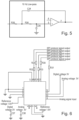
- the low-pass filtered voltage signal is converted into a second digital signal by a second analog-to-digital converter as illustrated in FIG. 6 , wherein the second analog-to-digital converter may adopt a model of ADS 1120, but the present disclosure is not limited thereto.
- the second analog-to-digital converter transmits the second digital signal to a micro-control unit through an SPI protocol to obtain functional near infrared data of the user's brain, and the micro-control unit transmits the functional near infrared data of the user's brain to a data processing device through a Bluetooth module for processing to obtain a functional near infrared spectrogram of the user's brain.
- the data of the user's brain may be transmitted to a host computer through a Wi-Fi module, a Zigbee module and/or a Bluetooth module, and the host computer processes the data of the user's brain and obtains the EEG and the functional near infrared data of the user's brain.
- a Wi-Fi module a Wi-Fi module
- a Zigbee module a Zigbee module
- a Bluetooth module a Bluetooth module
- step S104 the user's EEG and functional near infrared spectrogram are combined and analyzed to obtain the activity situation of the user's brain, thereby improving the accuracy of monitoring of the user's brain through the multimodal monitoring technology.
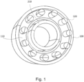
- the multimodal brain function signal acquisition device and method of the present disclosure dispose the near infrared signal acquisition device and the EEG signal acquisition device on the same cap, wherein the EEG signal of the user's brain is acquired by the EEG signal acquisition device, and the current signal of the user's brain is acquired by the near infrared signal acquisition device for processing to obtain the user's EEG and functional near infrared data, which are analyzed to obtain the activity situation of the same brain part of the user at the same time.
- the EEG and the functional near infrared data it is helpful to understand activity situations of the user's brain more accurately.
- the near infrared signal acquisition device and the EEG signal acquisition device are on the same cap, it is helpful to acquire the photoelectrical signals of the same brain part simultaneously, so that the detection and analysis of the same brain part are more accurate.
- the reflective coating on the inner wall of the light guide column can completely reflect the unabsorbed near infrared light to the photodiode, which is helpful for the photodiode to convert the unabsorbed near infrared light into current signals, and ensures the accuracy of the acquisition result of the near infrared signal acquisition device.
- the present disclosure further provides an improved EEG signal acquisition device.
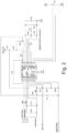
- the improved EEG signal acquisition device in addition to the support member 110 and the plurality of acquisition tentacles 120, the improved EEG signal acquisition device further includes an acquisition electrode module, a reference electrode module, a right-leg driving electrode module and an EEG signal output module.
- the first amplifier U2 having its input end accessing the electrical signal acquired by the acquisition electrode is a follower amplifier, which doubles the accessed signal to improve the impedance and isolate the interference.
- ELEC_IN represents an input end of the acquisition electrode module
- ANG_OUT represents an output end of the acquisition electrode module
- S_GND represents a signal ground
- VCC represents a power supply voltage
- AGND represents an analog ground
- Vref represents a third reference voltage.
- the other of the first amplifiers U2 has the input end connected to the output end of the second amplifier U1, and the output end connected to the input end of the second amplifier U1, so as to constitute a feedback circuit which is integrated to correct an input voltage bias.
- the EEG signal is weak, mainly at the mv level; if the test environment is in a strong electromagnetic environment, electromagnetic waves can easily interfere with the weak signal and drown it in noise; the EMG noise generated by exercise and the power frequency will also affect the signal.
- the solution improves the circuit from the source of the circuit design. Since the EEG signal is at the microvolt level and can be easily interfered by the environment, the signal is processed at the signal source in the present disclosure, and then the processed signal is transmitted to better shield the interference.
- the reference electrode module is configured to acquire an electrical signal at an earlobe based on a preset reference electrode, and includes a third amplifier U3, which has an input end accessing the electrical signal acquired by the reference electrode, and an output end connected to an output port of the reference electrode module to output a first reference voltage.
- ELEC_IN represents an input end of the reference electrode module
- Vref represents an output port of the reference electrode module
- S_GND represents a signal ground
- VCC represents a power supply voltage
- AGND represents an analog ground
- Vref represents a first reference voltage.
- a right-leg driving electrode module is configured to provide a driving voltage based on a preset right-leg driving electrode, and includes a fourth amplifier U4, which has an input end accessing a second reference voltage, and an output end connected to an output port of the right-leg driving electrode module.
- DRL represents an electrical signal output by the right-leg driving electrode module, i.e., a driving signal generated by the driving electrode.
- S GND represents a signal ground
- VCC represents a power supply voltage
- AGND represents an analog ground
- Vref represents a second reference voltage.
- the right-leg driving electrode module is configured to suppress a common-mode interference.
- the first reference voltage, the second reference voltage and the third reference voltage may be the same voltage parameter value.
- the EEG signal output module receives electrical signals output by the acquisition electrode module, the reference electrode module and the right-leg driving electrode module respectively, calculates, at each moment, a difference between voltage values of the electrical signals output by the acquisition electrode module and the reference electrode module, and a difference between voltage values of the electrical signals output by the acquisition electrode module and the right-leg driving electrode module respectively, and constructs a differential signal as an EEG signal based on the two differences.
- This solution adopted by the present disclosure is different from the prior art in which an electrical signal is output through a direct-driving electrode and then a differential signal is output.
- This solution adds a circuit for each electrode to further process the accessed electrical signal, thereby improving the anti-interference ability of the signal.
- this solution provides a feedback circuit for the acquisition electrode, so as to correct the input voltage bias and further improve the anti-interference ability of the signal.
- the first amplifier U2 with the input end connected to the output end of the second amplifier U1 is a feedback circuit amplifier
- a capacitor C2 is connected between an inverted input end and an output end of the feedback circuit amplifier
- an end of the capacitor C2 connected to the inverted input end of the feedback circuit amplifier is further connected to a resistor R8, and the capacitor C2 and the resistor R8 together constitute a feedback circuit of the acquisition electrode module.
- the feedback circuit is composed of the feedback circuit amplifier, the capacitor C2, the resistor R8, etc., so that the input voltage bias can be corrected, thereby further improving the anti-interference ability of the signal.
- the inverted input end of the feedback circuit amplifier is connected to a reference voltage supply end of the acquisition electrode module through the resistor R8, a non-inverted input end of the feedback circuit amplifier is connected to the reference voltage supply end of the acquisition electrode module through a resistor R7, and a resistor R3 is connected between the non-inverted input end of the feedback circuit amplifier and the output end of the second amplifier U1.
- a resistor R5 is connected between the output end of the feedback circuit amplifier and an inverted input end of the second amplifier U1.
- a loop is further disposed between the output end and the inverted input end of the second amplifier U1.
- the loop includes a resistor R4, a resistor R9, a resistor R6 and a capacitor C3, wherein one end of the resistor R4 is connected to the output end of the second amplifier U1, the resistor R9 and the capacitor C3 are connected in parallel, the other end of the resistor R4 is connected to one common end of the resistor R9 and the capacitor C3 connected in parallel, the other common end of the resistor R9 and the capacitor C3 connected in parallel is connected to one end of the resistor R6, and the other end of the resistor R6 is connected to the inverted input end of the second amplifier U1.
- the other common end of the resistor R9 and the capacitor C3 connected in parallel is further connected to the reference voltage supply end of the acquisition electrode module, so as to be provided with the third reference voltage.
- a non-inverted input end of the amplifier U3 of the reference electrode module accesses the electrical signal acquired by the reference electrode through the resistor R10, and an output end of the amplifier U3 outputs the first reference voltage through the resistor R11.
- the reference electrode module is configured to provide a reference calculation standard voltage, i.e., the first reference voltage, for signal calculation.
- a fifth pin of the amplifier U4 is supplied with a power supply voltage, and a capacitor C6 is connected in the connecting line with the analog ground; a second pin of amplifier U4 is connected to the analog ground; a first pin of the non-inverted input end of the amplifier U4 is connected to the analog ground.
- the reference electrode module further includes a resistor X1, which has one end connected to the analog ground, and the other end connected to one end of the resistor R12, and the other end of the resistor R12 is connected to the inverted input end of the amplifier U3.
- the error parameters of the capacitors and the resistors are calibrated in advance by the manufacturers.
- the acquisition electrode module, the reference electrode module and the right-leg driving electrode module in this solution have similar physical structures, which may include a probe, a circuit, a shielding cover and a shielding wire.
- the probe is connected to the circuit to input the acquired electrical signal thereto, the probe may be made of copper and silver plating, the probe is connected to the circuit through a base which may be made of cooper-plating silver or nickel-plating brass, and the base and the probe may be prepared by a computer numerical control (CNC) process to ensure the integration.
- the circuit structure is disposed on a circuit board, which may be connected to the base of the probe by welding.
- the shielding cover is a metal shell wrapping the parts above the electrode.
- the shielding wire is a shielding layer woven into a grid-shape with a characteristic impedance of 50 ohms.
- the structure of the electrode is a probe, i.e., a needle-type electrode.
- the electrode and the signal acquisition board are made together, the signal input is isolated by a designed follower circuit, and then it turns to a next stage of amplification circuit for processing.
- the reference electrode module circuit and the acquisition electrode module circuit acquire and process signals, and the right-leg driving electrode substantially filter out the common-mode signal.
- a higher common mode rejection ratio can be obtained through the gain of the amplifier circuit and by controlling the tolerances of components.
- the signal is output to the data processing end of the amplifier by ANG_OUT of the acquisition electrode module.
- the acquisition electrode, the reference electrode and the right-leg driving electrode in this solution all have power supplies and signal processing circuits, so that the common-mode noise can be suppressed and the input impedance can be increased.
- a total impedance balance formula is put forward, so that the calculated common-mode gain is close to zero.
- Another aspect of the present disclosure provides an improved EEG signal acquisition device, which includes an acquisition electrode module, a reference electrode module, a right-leg driving electrode module and an EEG signal output device.
- the right-leg driving electrode module is configured to provide a driving voltage based on a preset right-leg driving electrode, and includes a fourth amplifier U4, which has an input end connected to a second reference voltage, and an output end connected to an output port of the right-leg driving electrode module.
- the EEG signal output device receives the electrical signals output by the acquisition electrode, the reference electrode and the right-leg driving electrode respectively, calculates, at each moment, a difference between voltage values of the electrical signals output by the acquisition electrode and the reference electrode, and a difference between voltage values of the electrical signals output by the acquisition electrode and the right-leg driving electrode respectively, and constructs a differential signal as an EEG signal based on the two differences.
- the improved EEG signal acquisition device of the present disclosure adds a circuit for each electrode to further process the accessed electrical signal, thereby improving the anti-interference ability of the signal. Moreover, the improved EEG signal acquisition device of the present disclosure may be provided with a feedback circuit, so as to correct the input voltage bias and further improve the anti-interference ability of the signal.
- the improved EEG signal acquisition device of the present disclosure may also be used independently from the multimodal brain function signal acquisition device.
- the various exemplary components, systems, and methods described in conjunction with the embodiments disclosed herein can be implemented by hardware, software, or a combination thereof.
- the implementation mode depends on the specific application and design constraints of the technical solutions. Skilled persons can implement the described functions for each particular application using different methods, but such implementations should not be construed as going beyond the scope of the present disclosure.
- the hardware may be, for example, an electronic circuit, an application specific integrated circuit (ASIC), appropriate firmware, a plug-in, a function card, etc.
- ASIC application specific integrated circuit
- the elements of the present disclosure are programs or code segments that are used to perform required tasks.
- a program or code segment may be stored in a machine-readable medium, or transmitted in a transmission medium or a communication link by a data signal carried in a carrier wave.
Landscapes
- Health & Medical Sciences (AREA)
- Life Sciences & Earth Sciences (AREA)
- Physics & Mathematics (AREA)
- Engineering & Computer Science (AREA)
- Molecular Biology (AREA)
- General Health & Medical Sciences (AREA)
- Veterinary Medicine (AREA)
- Public Health (AREA)
- Animal Behavior & Ethology (AREA)
- Biophysics (AREA)
- Pathology (AREA)
- Biomedical Technology (AREA)
- Heart & Thoracic Surgery (AREA)
- Medical Informatics (AREA)
- Surgery (AREA)
- Neurology (AREA)
- Psychiatry (AREA)
- Signal Processing (AREA)
- Physiology (AREA)
- Spectroscopy & Molecular Physics (AREA)
- Psychology (AREA)
- Artificial Intelligence (AREA)
- Computer Vision & Pattern Recognition (AREA)
- Optics & Photonics (AREA)
- Power Engineering (AREA)
- Chemical & Material Sciences (AREA)
- Dispersion Chemistry (AREA)
- Neurosurgery (AREA)
- Measurement And Recording Of Electrical Phenomena And Electrical Characteristics Of The Living Body (AREA)
Applications Claiming Priority (2)
| Application Number | Priority Date | Filing Date | Title |
|---|---|---|---|
| CN202211726776.2A CN116584888A (zh) | 2022-12-30 | 2022-12-30 | 一种多模态脑功能信号采集装置及方法 |
| CN202211726822.9A CN116584953B (zh) | 2022-12-30 | 2022-12-30 | 一种改进型脑电信号采集系统及装置 |
Publications (3)
| Publication Number | Publication Date |
|---|---|
| EP4393376A1 true EP4393376A1 (de) | 2024-07-03 |
| EP4393376C0 EP4393376C0 (de) | 2025-05-21 |
| EP4393376B1 EP4393376B1 (de) | 2025-05-21 |
Family
ID=88745945
Family Applications (1)
| Application Number | Title | Priority Date | Filing Date |
|---|---|---|---|
| EP23208600.9A Active EP4393376B1 (de) | 2022-12-30 | 2023-11-08 | Multimodale gehirnfunktionssignalerfassungsvorrichtung und verfahren |
Country Status (3)
| Country | Link |
|---|---|
| US (1) | US20240215902A1 (de) |
| EP (1) | EP4393376B1 (de) |
| ES (1) | ES3031428T3 (de) |
Cited By (1)
| Publication number | Priority date | Publication date | Assignee | Title |
|---|---|---|---|---|
| CN119791683A (zh) * | 2025-01-18 | 2025-04-11 | 北京航空航天大学 | 高信噪比干电极脑电信号采集系统 |
Families Citing this family (3)
| Publication number | Priority date | Publication date | Assignee | Title |
|---|---|---|---|---|
| CN119961731A (zh) * | 2025-01-18 | 2025-05-09 | 安徽大学 | 一种脑机接口的信号采集及处理装置及脑机接口系统 |
| CN120128095B (zh) * | 2025-05-12 | 2025-09-19 | 小舟科技有限公司 | Eeg前置放大电路及脑机接口设备 |
| CN120203570B (zh) * | 2025-05-28 | 2025-09-02 | 哈尔滨工业大学(深圳)(哈尔滨工业大学深圳科技创新研究院) | 基于多模态数据的运动功能康复预测方法、系统、终端及存储介质 |
Citations (4)
| Publication number | Priority date | Publication date | Assignee | Title |
|---|---|---|---|---|
| FR2899089A1 (fr) * | 2006-03-28 | 2007-10-05 | Univ Picardie Jules Verne Etab | Dispositif de capteurs des signaux de l'activite cerebrale |
| KR20140089973A (ko) * | 2013-01-08 | 2014-07-16 | 한림대학교 산학협력단 | 의료용 센서 부착장치 |
| CN106618599A (zh) * | 2015-08-22 | 2017-05-10 | 由国峰 | 一种可穿戴式功能近红外光谱成像系统前端 |
| CN115054242A (zh) * | 2022-05-23 | 2022-09-16 | 哈工大机器人(合肥)国际创新研究院 | 用于混合脑机接口的光电极探头及采集帽 |
Family Cites Families (5)
| Publication number | Priority date | Publication date | Assignee | Title |
|---|---|---|---|---|
| JP3725156B2 (ja) * | 1995-01-03 | 2005-12-07 | ノン−インヴェイシヴ テクノロジイ,インク. | 生物組織の生体内検査用の光学カプラ |
| EP3184043A1 (de) * | 2015-12-22 | 2017-06-28 | IMEC vzw | Sensor, system und halteanordnung für biosignalaktivitätsmessung |
| US10799161B2 (en) * | 2016-04-04 | 2020-10-13 | Technische Universität Berlin | Biosignal acquisition device and system, method for acquisition of biosignals |
| WO2019000088A1 (en) * | 2017-06-26 | 2019-01-03 | The University Of British Columbia | ELECTROENCEPHALOGRAPHIC DEVICE AND DEVICE FOR MONITORING A SUBJECT USING NEAR-INFRARED SPECTROSCOPY |
| CN107137079B (zh) * | 2017-06-28 | 2020-12-08 | 京东方科技集团股份有限公司 | 基于脑信号控制设备的方法、其控制设备及人机交互系统 |
-
2023
- 2023-11-08 EP EP23208600.9A patent/EP4393376B1/de active Active
- 2023-11-08 US US18/504,543 patent/US20240215902A1/en active Pending
- 2023-11-08 ES ES23208600T patent/ES3031428T3/es active Active
Patent Citations (4)
| Publication number | Priority date | Publication date | Assignee | Title |
|---|---|---|---|---|
| FR2899089A1 (fr) * | 2006-03-28 | 2007-10-05 | Univ Picardie Jules Verne Etab | Dispositif de capteurs des signaux de l'activite cerebrale |
| KR20140089973A (ko) * | 2013-01-08 | 2014-07-16 | 한림대학교 산학협력단 | 의료용 센서 부착장치 |
| CN106618599A (zh) * | 2015-08-22 | 2017-05-10 | 由国峰 | 一种可穿戴式功能近红外光谱成像系统前端 |
| CN115054242A (zh) * | 2022-05-23 | 2022-09-16 | 哈工大机器人(合肥)国际创新研究院 | 用于混合脑机接口的光电极探头及采集帽 |
Non-Patent Citations (1)
| Title |
|---|
| XU JIAWEI ET AL: "A 665 [mu]W Silicon Photomultiplier-Based NIRS/EEG/EIT Monitoring ASIC for Wearable Functional Brain Imaging", IEEE TRANSACTIONS ON BIOMEDICAL CIRCUITS AND SYSTEMS, IEEE, US, vol. 12, no. 6, 31 December 2018 (2018-12-31), pages 1267 - 1277, XP011695342, ISSN: 1932-4545, [retrieved on 20190101], DOI: 10.1109/TBCAS.2018.2883289 * |
Cited By (1)
| Publication number | Priority date | Publication date | Assignee | Title |
|---|---|---|---|---|
| CN119791683A (zh) * | 2025-01-18 | 2025-04-11 | 北京航空航天大学 | 高信噪比干电极脑电信号采集系统 |
Also Published As
| Publication number | Publication date |
|---|---|
| US20240215902A1 (en) | 2024-07-04 |
| EP4393376C0 (de) | 2025-05-21 |
| ES3031428T3 (en) | 2025-07-08 |
| EP4393376B1 (de) | 2025-05-21 |
Similar Documents
| Publication | Publication Date | Title |
|---|---|---|
| EP4393376B1 (de) | Multimodale gehirnfunktionssignalerfassungsvorrichtung und verfahren | |
| Seok et al. | Motion artifact removal techniques for wearable EEG and PPG sensor systems | |
| US12011275B2 (en) | Method and apparatus for wide-band phase gradient signal acquisition | |
| Chi et al. | Wireless non-contact cardiac and neural monitoring | |
| Sawan et al. | Wireless recording systems: from noninvasive EEG-NIRS to invasive EEG devices | |
| Guo et al. | Development of a multi-channel compact-size wireless hybrid sEMG/NIRS sensor system for prosthetic manipulation | |
| von Lühmann et al. | M3BA: a mobile, modular, multimodal biosignal acquisition architecture for miniaturized EEG-NIRS-based hybrid BCI and monitoring | |
| Safaie et al. | Toward a fully integrated wireless wearable EEG-NIRS bimodal acquisition system | |
| Guermandi et al. | A driving right leg circuit (DgRL) for improved common mode rejection in bio-potential acquisition systems | |
| US20050043608A1 (en) | Method and apparatus for non-contact monitoring of cellular bioactivity | |
| KR101669436B1 (ko) | 사용자의 상태를 관리하는 머리착용형 장치 및 사용자의 상태를 관리하는 방법 | |
| Matthews et al. | Novel hybrid bioelectrodes for ambulatory zero-prep EEG measurements using multi-channel wireless EEG system | |
| Jiang et al. | IEMS: An IoT-empowered wearable multimodal monitoring system in neurocritical care | |
| Jakab et al. | Novel wireless electroencephalography system with a minimal preparation time for use in emergencies and prehospital care | |
| CN119837506B (zh) | 电生理及血液动力学多模态智能可穿戴系统及数据评估方法 | |
| CA3120321A1 (en) | Contactless electrode for sensing physiological electrical activity | |
| CN113100776A (zh) | 一种融合肌电和心电信号的疲劳监测系统及方法 | |
| Zhao et al. | Signal quality and electrode-skin impedance evaluation in the context of wearable electroencephalographic systems | |
| Nyni et al. | Wireless health monitoring system for ECG, EMG and EEG detecting | |
| Cui et al. | A wireless integrated EEG–fNIRS system for brain function monitoring | |
| CN106691375A (zh) | 一种近红外光谱成像系统 | |
| Rakhmatulin et al. | Low-cost brain computer interface for everyday use | |
| CN117752341B (zh) | 一体式脑信号采集装置、采集方法及采集电路 | |
| Mihajlović et al. | Noninvasive wearable brain sensing | |
| CN116584888A (zh) | 一种多模态脑功能信号采集装置及方法 |
Legal Events
| Date | Code | Title | Description |
|---|---|---|---|
| PUAI | Public reference made under article 153(3) epc to a published international application that has entered the european phase |
Free format text: ORIGINAL CODE: 0009012 |
|
| STAA | Information on the status of an ep patent application or granted ep patent |
Free format text: STATUS: REQUEST FOR EXAMINATION WAS MADE |
|
| 17P | Request for examination filed |
Effective date: 20231108 |
|
| AK | Designated contracting states |
Kind code of ref document: A1 Designated state(s): AL AT BE BG CH CY CZ DE DK EE ES FI FR GB GR HR HU IE IS IT LI LT LU LV MC ME MK MT NL NO PL PT RO RS SE SI SK SM TR |
|
| GRAP | Despatch of communication of intention to grant a patent |
Free format text: ORIGINAL CODE: EPIDOSNIGR1 |
|
| STAA | Information on the status of an ep patent application or granted ep patent |
Free format text: STATUS: GRANT OF PATENT IS INTENDED |
|
| RIC1 | Information provided on ipc code assigned before grant |
Ipc: A61B 5/384 20210101ALI20250107BHEP Ipc: A61B 5/31 20210101ALI20250107BHEP Ipc: A61B 5/291 20210101ALI20250107BHEP Ipc: A61B 5/265 20210101ALI20250107BHEP Ipc: A61B 5/1455 20060101ALI20250107BHEP Ipc: A61B 5/00 20060101AFI20250107BHEP |
|
| INTG | Intention to grant announced |
Effective date: 20250123 |
|
| GRAS | Grant fee paid |
Free format text: ORIGINAL CODE: EPIDOSNIGR3 |
|
| GRAA | (expected) grant |
Free format text: ORIGINAL CODE: 0009210 |
|
| STAA | Information on the status of an ep patent application or granted ep patent |
Free format text: STATUS: THE PATENT HAS BEEN GRANTED |
|
| RAP1 | Party data changed (applicant data changed or rights of an application transferred) |
Owner name: KINGFAR INTERNATIONAL INC. Owner name: NANJING KINGFAR HEALTH TECHNOLOGY INC. |
|
| AK | Designated contracting states |
Kind code of ref document: B1 Designated state(s): AL AT BE BG CH CY CZ DE DK EE ES FI FR GB GR HR HU IE IS IT LI LT LU LV MC ME MK MT NL NO PL PT RO RS SE SI SK SM TR |
|
| REG | Reference to a national code |
Ref country code: GB Ref legal event code: FG4D |
|
| REG | Reference to a national code |
Ref country code: CH Ref legal event code: EP |
|
| REG | Reference to a national code |
Ref country code: IE Ref legal event code: FG4D |
|
| U01 | Request for unitary effect filed |
Effective date: 20250526 |
|
| U07 | Unitary effect registered |
Designated state(s): AT BE BG DE DK EE FI FR IT LT LU LV MT NL PT RO SE SI Effective date: 20250603 |
|
| REG | Reference to a national code |
Ref country code: ES Ref legal event code: FG2A Ref document number: 3031428 Country of ref document: ES Kind code of ref document: T3 Effective date: 20250708 |
|
| PG25 | Lapsed in a contracting state [announced via postgrant information from national office to epo] |
Ref country code: NO Free format text: LAPSE BECAUSE OF FAILURE TO SUBMIT A TRANSLATION OF THE DESCRIPTION OR TO PAY THE FEE WITHIN THE PRESCRIBED TIME-LIMIT Effective date: 20250821 |
|
| PG25 | Lapsed in a contracting state [announced via postgrant information from national office to epo] |
Ref country code: PL Free format text: LAPSE BECAUSE OF FAILURE TO SUBMIT A TRANSLATION OF THE DESCRIPTION OR TO PAY THE FEE WITHIN THE PRESCRIBED TIME-LIMIT Effective date: 20250521 |
|
| PG25 | Lapsed in a contracting state [announced via postgrant information from national office to epo] |
Ref country code: HR Free format text: LAPSE BECAUSE OF FAILURE TO SUBMIT A TRANSLATION OF THE DESCRIPTION OR TO PAY THE FEE WITHIN THE PRESCRIBED TIME-LIMIT Effective date: 20250521 |
|
| PG25 | Lapsed in a contracting state [announced via postgrant information from national office to epo] |
Ref country code: RS Free format text: LAPSE BECAUSE OF FAILURE TO SUBMIT A TRANSLATION OF THE DESCRIPTION OR TO PAY THE FEE WITHIN THE PRESCRIBED TIME-LIMIT Effective date: 20250821 |
|
| PG25 | Lapsed in a contracting state [announced via postgrant information from national office to epo] |
Ref country code: IS Free format text: LAPSE BECAUSE OF FAILURE TO SUBMIT A TRANSLATION OF THE DESCRIPTION OR TO PAY THE FEE WITHIN THE PRESCRIBED TIME-LIMIT Effective date: 20250921 |
|
| U1N | Appointed representative for the unitary patent procedure changed after the registration of the unitary effect |
Representative=s name: LORENZ SEIDLER GOSSEL PART. MBB; DE |
|
| U20 | Renewal fee for the european patent with unitary effect paid |
Year of fee payment: 3 Effective date: 20251125 |
|
| PG25 | Lapsed in a contracting state [announced via postgrant information from national office to epo] |
Ref country code: SM Free format text: LAPSE BECAUSE OF FAILURE TO SUBMIT A TRANSLATION OF THE DESCRIPTION OR TO PAY THE FEE WITHIN THE PRESCRIBED TIME-LIMIT Effective date: 20250521 |
|
| PG25 | Lapsed in a contracting state [announced via postgrant information from national office to epo] |
Ref country code: CZ Free format text: LAPSE BECAUSE OF FAILURE TO SUBMIT A TRANSLATION OF THE DESCRIPTION OR TO PAY THE FEE WITHIN THE PRESCRIBED TIME-LIMIT Effective date: 20250521 |
|
| PG25 | Lapsed in a contracting state [announced via postgrant information from national office to epo] |
Ref country code: SK Free format text: LAPSE BECAUSE OF FAILURE TO SUBMIT A TRANSLATION OF THE DESCRIPTION OR TO PAY THE FEE WITHIN THE PRESCRIBED TIME-LIMIT Effective date: 20250521 |
|
| PGFP | Annual fee paid to national office [announced via postgrant information from national office to epo] |
Ref country code: ES Payment date: 20251201 Year of fee payment: 3 |
|
| PLBE | No opposition filed within time limit |
Free format text: ORIGINAL CODE: 0009261 |
|
| STAA | Information on the status of an ep patent application or granted ep patent |
Free format text: STATUS: NO OPPOSITION FILED WITHIN TIME LIMIT |
|
| REG | Reference to a national code |
Ref country code: CH Ref legal event code: L10 Free format text: ST27 STATUS EVENT CODE: U-0-0-L10-L00 (AS PROVIDED BY THE NATIONAL OFFICE) Effective date: 20260402 |
|
| 26N | No opposition filed |
Effective date: 20260224 |