EP4393385B1 - Vorrichtung zur erfassung und verarbeitung eines photoelektrischen physiologischen signals - Google Patents
Vorrichtung zur erfassung und verarbeitung eines photoelektrischen physiologischen signals Download PDFInfo
- Publication number
- EP4393385B1 EP4393385B1 EP23203020.5A EP23203020A EP4393385B1 EP 4393385 B1 EP4393385 B1 EP 4393385B1 EP 23203020 A EP23203020 A EP 23203020A EP 4393385 B1 EP4393385 B1 EP 4393385B1
- Authority
- EP
- European Patent Office
- Prior art keywords
- signal
- light
- light source
- digital
- physiological
- Prior art date
- Legal status (The legal status is an assumption and is not a legal conclusion. Google has not performed a legal analysis and makes no representation as to the accuracy of the status listed.)
- Active
Links
Images

Classifications
-
- A—HUMAN NECESSITIES
- A61—MEDICAL OR VETERINARY SCIENCE; HYGIENE
- A61B—DIAGNOSIS; SURGERY; IDENTIFICATION
- A61B5/00—Measuring for diagnostic purposes; Identification of persons
- A61B5/02—Detecting, measuring or recording for evaluating the cardiovascular system, e.g. pulse, heart rate, blood pressure or blood flow
- A61B5/024—Measuring pulse rate or heart rate
- A61B5/02416—Measuring pulse rate or heart rate using photoplethysmograph signals, e.g. generated by infrared radiation
- A61B5/02427—Details of sensor
-
- A—HUMAN NECESSITIES
- A61—MEDICAL OR VETERINARY SCIENCE; HYGIENE
- A61B—DIAGNOSIS; SURGERY; IDENTIFICATION
- A61B5/00—Measuring for diagnostic purposes; Identification of persons
- A61B5/145—Measuring characteristics of blood in vivo, e.g. gas concentration or pH-value ; Measuring characteristics of body fluids or tissues, e.g. interstitial fluid or cerebral tissue
- A61B5/1455—Measuring characteristics of blood in vivo, e.g. gas concentration or pH-value ; Measuring characteristics of body fluids or tissues, e.g. interstitial fluid or cerebral tissue using optical sensors, e.g. spectral photometrical oximeters
- A61B5/14551—Measuring characteristics of blood in vivo, e.g. gas concentration or pH-value ; Measuring characteristics of body fluids or tissues, e.g. interstitial fluid or cerebral tissue using optical sensors, e.g. spectral photometrical oximeters for measuring blood gases
- A61B5/14552—Details of sensors specially adapted therefor
-
- A—HUMAN NECESSITIES
- A61—MEDICAL OR VETERINARY SCIENCE; HYGIENE
- A61B—DIAGNOSIS; SURGERY; IDENTIFICATION
- A61B5/00—Measuring for diagnostic purposes; Identification of persons
- A61B5/72—Signal processing specially adapted for physiological signals or for diagnostic purposes
-
- A—HUMAN NECESSITIES
- A61—MEDICAL OR VETERINARY SCIENCE; HYGIENE
- A61B—DIAGNOSIS; SURGERY; IDENTIFICATION
- A61B5/00—Measuring for diagnostic purposes; Identification of persons
- A61B5/72—Signal processing specially adapted for physiological signals or for diagnostic purposes
- A61B5/7225—Details of analogue processing, e.g. isolation amplifier, gain or sensitivity adjustment, filtering, baseline or drift compensation
Definitions
- the present application relates to a technical field of physiological signal acquisition, and, in particular, to a photoelectric physiological signal acquiring and processing device.
- FIG. 3 A physiological signal acquisition technology in existing technologies is shown in FIG. 3 , in which a voltage divider circuit is composed of a fixed resistance value resistance and a photodiode.
- the photodiode receives a varied optical signal
- the voltage divider circuit receives a varied current to obtain a varied voltage signal.
- the voltage signal obtained from the voltage divider resistance is output to an analog-to-digital device through a circuit that integrates filtering and amplification, and then to a microprocessing unit, where the physiological signal is regained.
- Wavelength and intensity of the light used in the physiological signal acquisition in the physiological acquisition device are preset.
- the technical problem present in the existing technology is that, a reverse current generated by the photodiode is different from the preset value due to a simultaneous irradiation of the light of other wavelengths on the photodiode, thereby interfering with signal acquisition.
- an interference light source with a wavelength quite different from that of the preset light source in conjunction with the photodiode, it was found that the photodiode cannot filter out all other lights than a light having desired specific radiation frequency band, still suffering certain interference.
- the filtering device can only achieve an attenuate at a certain rate regarding the light beyond a cutoff frequency, rather than completely filtering out the interference light. Furthermore, a method of introducing the filtering device into the circuit requires knowing a luminous frequency of the interference light source in advance to determine the cutoff frequency of the filtering device on the circuit. If the frequency of the light emitted by the interference light source is similar to the physiological signal of the human body, the interference light can not be removed by introducing the filtering device into the circuit.
- KAO YUNG-HUA ET AL in "Towards maximizing the sensing accuracy of an cuffless, optical blood pressure sensor using a high-order front-end filter", MICROSYSTEM TECHNOLOGIES, BERLIN, DE, vol. 24, no. 11, 6 April 2018 (2018-04-06), pages 4621-4630, XP036614678 ,ISSN: 0946-7076, DOI: 10.1007/S00542-018-3877-3 [retrieved on 2018-04-06 ] describes a high-order filter as part of an analog front-end circuit for an optical, cuffless photoplethysmography (PPG) sensor is developed to maximize the sensing accuracy of measured blood pressures (BPs).
- PPG photoplethysmography
- the BP device consists physicallyof light emitting diodes and photo-diodes (PDs) to sense the dynamic change of intravascular blood volume based on the known principle of PPG and then calculate the BP based on reflective pule transient time in a PPG signal.
- the photoplethysmography (PPG) signal acquired by the PDs are expected to be processed by an excellent front-end circuitry toreduce its noise and DC offset but without much distortion to obtain accurate BP prediction.
- This front-end is accomplishedherein by a transimpedance amplifier, a critical high-order band-pass filter and a programmable gain amplifier, which isfollowed by microprocessor and a wireless module.
- the band-pass filter is optimized with a passband from 0.2 to 7.2 Hz, where the low-pass is in a 4th order while the high-pass is in 2nd order.
- the low-pass is designed for reducing noisedincluding those due to ambient lighting, while the high-pass is for reducing DC drifting caused mainly by breathing and/orsubject slow motion. 46 subjects were tested with the designed high-order filters in comparison with reference device.
- a physiological data monitoring system measures at least one physiological characteristic wherein the physiological data monitoring system comprises a sensor unit and a monitoring unit in data communication with the sensor unit.
- the monitoring unit has a sonification module that comprises one programmable sound generator module to produce a plurality of signals indicative of a physiological parameter and a memory module for storing a plurality of control parameters for managing the programmable sound generator module, wherein the plurality of signals produced have a plurality of frequencies modified in accordance with at least one physiological data value.
- the patent application US 20150196257A1 discloses a system and method for signal processing to remove unwanted noise components including: (i) wavelength-independent motion artifacts such as tissue, bone and skin effects, and (ii) wavelength-dependent motion artifact/noise components such as venous blood pulsation and movement due to various sources including muscle pump, respiratory pump and physical perturbation.
- a pulse wave sensor which includes a light sensor unit arranged to irradiate a living body with light from a light emitting unit and to detect reflected light or transmitted light from the living body by a light receiving unit, so as to generate a current signal corresponding to received light intensity, a pulse drive unit arranged to turn on and off the light emitting unit at a predetermined frame frequency and duty, a transimpedance amplifier arranged to convert the current signal into a voltage signal, and a mounting determination unit arranged to perform mounting determination by comparing an OFF voltage signal obtained by the transimpedance amplifier during an OFF period of the light emitting unit with a predetermined first threshold voltage.
- the patent US 9220409B2 discloses a processing circuitry for processing a physiological signal such as a light signal attenuated by a subject.
- the physiological signal may include a desired component and an undesired component.
- a first filtering operation may be performed to remove at least a portion of the undesired component and a second filtering operation may be performed to reduce an undesired distortion introduced by the first filter.
- the transfer function of the second filter may be substantially the inverse of the transfer function of the first filter.
- One or more physiological parameters may be determined based on the filtered physiological signal.
- the patent CN 102512178B discloses a blood oxygen measurement device and method.
- the device comprises: a photocurrent signal acquisition unit, a signal conversion unit, an ambient light signal filtering unit, a voltage signal amplifying unit, an analog-to-digital conversion unit, a waveform signal extraction unit, a noise analysis unit, a waveform processing unit, and a blood oxygen data calculation unit are connected in sequence according to the signal flow direction, and the ambient light signal filtering unit is connected to the signal conversion unit and is used to filter out the interference of the ambient light signal.
- the patent application US 20160296129A1 discloses a biological information detection apparatus, which includes a sensor having a light emitter that radiates light to a subject and a light receiver that receives light from the subject, and a contact part to be in contact with the subject. Supposing that light power from the light emitter passing through a living body and entering the light receiver is PS and a distance from the light receiver to an end portion of the contact part is rN, and light power of disturbance light from outside of the end portion passing through the living body and entering the light receiver is PN(rN) as a function of rN, an attenuation rate ⁇ of the disturbance light is set to satisfy rN ⁇ 10 mm and ⁇ ⁇ PS/ ⁇ PN(rN) ⁇ 1000 ⁇ .
- the patent US 5807267A provide the user with a reliable heart rate monitor that is a completely self contained unit and is capable of providing accurate readings while the wearer is moving about.
- the use of piezoelectric sensing elements eliminates the power drain caused by LEDs and similar devices.
- the sensing element mounting means disclosed herein is devised to greatly reduce the noise introduced into the pulse signal by body motion.
- the use of optical sensors in a staring mode and optical sensors in a pulsed mode is also presented.
- the effects of noise are further reduced by employing digital signal processing algorithms to find the heart pulse intermixed with noise signals and present the heart pulse rate in beats per minute on a display.
- the resulting device permits the visual monitoring of the heart pulse rate in a human body in a consistent, error-free manner.
- Such a device and method allow the enhancement of the performance of the PPG sensors compared to conventional apparatus and methods.
- the presented sensor and methodology have been integrated into a prototype device for noninvasive, continuous, wearable, remote and mobile monitoring of human vital signs, such as heart rate, oxygen saturation, blood pressure, respiration rate, etc. This small device allows the user to read, store, process and transmit all the measurements made using the PPG optical sensor and the electronic unit to a remote location.
- the patent application WO 2011117780A1 discloses a method of and device for monitoring a vital parameter of a patient by emitting light onto tissue of the patient with at least one light source and collecting light which is transmitted through the tissue and/or which is reflected from the tissue.
- the emitted light is multiplexed according to a predefined multiplexing scheme having a plurality of multiplexing channels, and the collected light is detected according to the predefined multiplexing scheme, resulting in a plurality of detection channels.
- At least one of the multiplexing channels is arranged to be a dark multiplexing channel for which no light is emitted by the at least one light source, resulting in a dark detection channel, and the signal of this dark detection channel is used for generating a reference signal for reducing interference in the signal of at least one of the other detection channels.
- connection in the article can not only refer to a direct connection, but also to an indirect connection with an intermediate object.
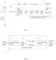
- the present application provides a photoelectric physiological signal acquiring and processing device, which includes a light source 1, a photoelectric sensing device 3, an acquisition circuit 4, an analog-to-digital device 5, and a microprocessing unit 6.
- a light source 1 a photoelectric sensing device 3
- an acquisition circuit 4 an analog-to-digital device 5
- a microprocessing unit 6 Light having a specific wavelength and a light intensity emitted by the light source 1 and required for acquiring a physiological signal is transmitted through or reflected by a human physiological signal acquisition site before being irradiated on the photoelectric sensing device 3.
- the photoelectric sensing device 3 converts an optical signal into a current signal and outputs the current signal to the acquisition circuit 4.
- the current signal is converted into a processed voltage signal by the acquisition circuit 4, and the voltage signal is output to the analog-to-digital device 5.
- the voltage signal is converted into a digital signal by the analog-to-digital device 5, and the digital signal is output to the microprocessing unit 6.
- a data signal is processed by the microprocessing unit 6 to obtain the physiological signal.
- the physiological signal can be a pulse signal or a blood oxygen signal.
- the human physiological signal acquisition site refers to a skin that can be irradiated by the light emitted by the light source 1 at any point in the human body.
- the light source 1 is configured to emit a light of a specific wavelength and light intensity required for acquiring the physiological signal; and the light source 1 can use a single light source or multiple light sources to emit the light.
- the light emitted by the light source 1 includes one or more light rays, including those having specific wavelength and light intensity required for the physiological signal acquisition.
- the wavelength of the light emitted by the light source 1 is a preset light wavelength suitable for the physiological signal acquisition, which is selected according to a wavelength range of a visible spectrum.
- the acquisition circuit 4 is configured for filtering and amplifying the varied current signal to obtain a processed varied voltage signal.
- the acquisition circuit 4 includes a current-to-voltage conversion module 41, a filtering device 42, and an amplification circuit 43.
- the current-to-voltage conversion module 41 converts a current signal into a voltage signal and outputs the voltage signal to the filtering device 42.
- the filtering device 42 filters the voltage signal and outputs a filtered voltage signal to the amplification circuit 43.
- the amplification circuit 43 amplifies the filtered voltage signal and outputs the amplified voltage signal to the analog-to-digital device 5.
- the current-to-voltage conversion module 41 is a trans-impedance amplifier; the filtering device 42 is a band-pass filter which only allows the passing through of an electrical signal having a specific frequency band that is generated by irradiating the light having the specific wavelength and light intensity emitted by the light source 1 for acquiring the physiological signal on the photoelectric sensing device 3. Due to a possible presence of an interference light other than the light emitted by the light source 1 in the optical signal acquired by a photoelectric converter, there may also be a current signal converted from the interference light present in a converted current signal.
- the trans-impedance amplifier to process the varied current signal, only current-to-voltage conversion is performed, that is, converting a varied current signal into a varied voltage signal, without amplifying the varied current signal, thereby avoiding amplifying the interference signal during signal conversion. Since there may still be the voltage signal converted from the interfering light present in the voltage signal formed by a conversion of the trans-impedance amplifier, the varied voltage signal is firstly filtered through the band-pass filter firstly, so as to further filter out the voltage signal converted from the interference signal in the varied voltage signal, and then a filtered voltage signal is amplified by the amplification circuit 43 to obtain a processed varied voltage signal. This avoids a problem of simultaneously amplifying the interference signal in an circuit with integrated filtering and amplification.
- a frequency of the pulse signal is in a range of 0.1-40Hz, and a spectrum is in a range of 0-20Hz. Therefore, a passband of the band-pass filter is in a range of 0.1-20Hz, which ensures that the pulse signal can pass through and other interference signals will be attenuated.
- the microprocessing unit 6 is configured to receive the digital signal from the analog-to-digital device 5 and regain a corresponding acquired physiological signal from the received digital signal.
- the photoelectric physiological signal acquiring and processing device is configured to acquire the pulse signal.
- the photoelectric sensing device 3 adopts a photodiode
- the light source 1 adopts a light emitting diode to emit a light having a specific wavelength and light intensity required for acquiring the pulse signal.
- the light source 1 is closely attached to a position on human skin where light rays transmitted through or reflected by a human pulse signal acquisition site irradiates, so as to acquire the light transmitted through or reflected by a human pulse signal acquisition site, so as to minimize an acquisition of a signal from an environmental light as much as possible.
- the photodiode converts an acquired varied optical signal into a varied current signal, the varied current signal is converted into a varied voltage signal via the trans-impedance amplifier, the varied voltage signal is filtered through the band-pass filter, and the filtered voltage signal is amplified by the amplification circuit 43 to obtain a processed varied voltage signal.
- the varied voltage signal is converted into a corresponding digital signal through an analog-to-digital converter and transmitted to the microprocessing unit 6, the microprocessing unit 6 regains the acquired pulse signal according to the obtained digital signal.
- a specific principle includes utilizing the converted voltage signal to obtain a corresponding PPG waveform (photoplethysmography), thereby obtaining a corresponding pulse signal.
- a spectral response range of the photodiode only refers to the wavelength range of a most sensitive spectral response of the photodiode, it cannot completely filter out the light of other wavelengths outside the spectral response range. Therefore, the light of different wavelengths emitted by the light source 1 will interfere with the physiological signal acquisition, resulting in inaccurate acquisition of physiological signal data.
- the existing technology can only achieve a certain degree of attenuation of the optical signals that generate interference regarding a problem of mutual interference between multiple optical signals of different wavelengths, and cannot completely filter out the interference signal, so it cannot effectively solve the interference problem mentioned above. Referring to FIG. 1 and FIG.
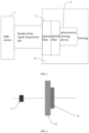
- the photoelectric physiological signal acquiring and processing device mentioned above further includes an optical filtering unit 2, which closely attaches and covers the photoelectric sensing device 3.
- the optical filtering unit 2 adopts an optical filter, in which a number of the optical filter may not necessarily be two layers, and, instead, can be selected as having more than one layer of closely connected optical filters according to an usage scenario of the photoelectric physiological signal acquiring and processing device.
- an optical filter By filtering out an ambient light, an impact of the light of other wavelengths than the specific wavelength set for acquiring the physiological signal on the physiological signal acquisition is eliminated.
- an band range that allows the light passing through each layer optical filter of a multi-layer optical filter includes the wavelength of the light required for the physiological signal acquisition.
- a refractive index of a single-layer optical filter is generally around 92%.
- the single-layer filter can be selected to shield the interference light.
- the single-layer filter may not be able to completely shield the light of other wavelengths required for the physiological signal acquisition, therefore, the multi-layer filters can be selected to better shield an influence of other lights beyond a required wavelength, such as a double-layer filter, a three-layer filter, etc.
- a principle of the optical filtering unit 2 is to prepare the unit by adding special dyes to a plastic or a glass substrate or plate an optical film on its surface, so as to attenuate or absorb certain light bands in a light wave, or to accurately select a small range of the light wave to pass through, while a reflector may absorb other unwanted wave bands.
- a main wavelength selected for a selection of the optical filtering unit 2 as an example, when different lights of the wavelengths are irradiated on the optical filtering unit 2, only the lights from the small range of radiation wave bands near the main wavelength is allowed to pass through, while the lights of other wave bands are absorbed or reflected.
- a shading rate of the optical filtering unit 2 is generally around 92%, and an use of multi-layer optical filtering unit 2 can improve the shading rate and better shield an impact of other wavelengths of the light outside the passband of the optical filtering unit 2.
- the photodiode is based on the peak wavelength of the selected photodiode.
- the lights of the different wavelengths emitted by the light source 1 are irradiated on the optical filter, and the peak wavelength of the photodiode matches the main wavelength of a corresponding optical filter, so that the wavelength range of the light that can pass through the optical filter is within the spectral response range of a corresponding photodiode, the optical filter and the photodiode used in combination serve as a secondary shielding for the interference light, thereby significantly reducing or even avoiding the interference light outside the spectral response range of the photodiode from irradiating on the photodiode, affecting a reverse current generated by the photodiode.
- the selection of the optical filtering unit 2 and the photoelectric sensing device 3 are correspondingly selected so that the wavelength range of the light that can pass through the optical filtering unit 2 is within the spectral response range of the photoelectric sensing device 3.
- a selection standard for setting the photodiode is the peak wavelength of 530nm ⁇ 10nm
- the selection standard of the corresponding optical filter is the main wavelength of 530nm.
- the optical filter only allows the green light with the wavelength of around 530nm to pass through, and the green light passing through the optical filter is within the spectral response range of the corresponding photodiode, thereby directly preventing the light from other radiation wave bands from irradiating on the photodiode and ensuring an accuracy of the physiological signal acquisition.
- the optical filtering unit 2 is selected as a band-pass optical filter
- the photoelectric sensing device 3 is selected as the photodiode.
- the specific wavelength and corresponding light intensity of the light used to acquire the pulse signal are determined, and types of the band-pass optical filter and photodiode according to the wavelength of the light emitted by the light source 1 are selected, so that only the light of the specific wavelength is allowed to pass through.
- the light emitting diode is used to emit the lights of the specific wavelength and the light intensity for acquiring the pulse signal, the light emitted by light source 1 irradiates on the human body at a location suitable for acquiring the pulse signal, such as an earlobe or a finger.
- the obtained digital signal can be transmitted to the microprocessing unit 6 through the trans-impedance amplifier, the filtering device 42, the amplification circuit 43, and the analog-to-digital device 5 in sequence, and the microprocessing unit 6 can regain a acquired pulse signal according to the obtained digital signal.
- the photoelectric physiological signal acquiring and processing device mentioned above further includes a power controller 7, which controls a switch of the light source 1.
- the power controller 7 controls the light source 1 to turn on
- the light source 1 emits the light
- the microprocessing unit 6 receives a first digital signal
- the optical signal acquired by the photoelectric converter corresponding to the first digital signal includes the light emitted by the light source 1 and the interference light in the environment.
- the microprocessing unit 6 When the power controller 7 controls the light source 1 to turn off, the light source 1 does not emit the light, and the microprocessing unit 6 receives a second digital signal, at this time, the optical signal acquired by the photoelectric converter corresponding to the second digital signal includes the interference light in the environment; the microprocessing unit 6 processes a difference between the first digital signal and the second digital signal to obtain the physiological signal.
- the digital signal corresponding to the interference light in the environment is subtracting from the light emitted by the light source 1 and the digital signal corresponding to the interference light in the environment acquired by the photoelectric converter, thereby eliminating the impact of the ambient light with the same wavelength as the set light for acquiring the physiological signal on the physiological signal acquisition.
- An application environment of the photoelectric physiological signal acquiring and processing device should avoid the environment where the ambient light is too intense and a flashing frequency is too fast, ensuring a filtering efficiency of the optical filtering unit 2 for the ambient light, and ensuring the accuracy of acquiring the same wavelength of the light in the ambient light as the set light for acquiring the physiological signal.
- the photoelectric physiological signal acquiring and processing device mentioned above further includes a housing 8, which is wrapped at a position outside the photoelectric sensing device 3 that is not irradiated by the light emitted by the light source 1 and transmitted through or reflected light through the human physiological signal acquisition site.
- a size of the optical filtering unit 2 is larger than that of the photodiode, and the photodiode and the optical filtering unit 2 are closely attached together.
- the housing 8 completely covers a position outside of the optical filtering unit 2 and the photodiode receiving projected or reflected light, ensuring that the photodiode does not receive the light signals of other wavelengths as much as possible, thereby acquiring more accurate physiological signals.
- the exemplary components, systems, and methods described in conjunction with the disclosed embodiments can be executed in the hardware, software, or a combination of the two. Whether to execute it in the hardware or software depends on a specific application and design constraints of the technical solution. Professional and technical personnel can use different methods to achieve the described functions for each specific application, but such implementation should not be considered beyond the scope of the present application.
- the hardware it can be, for example, electronic circuits, application specific integrated circuits (ASICs), appropriate firmware, plugins, function cards, etc.
- ASICs application specific integrated circuits
- the elements of the present application are programs or code segments configured to execute the required tasks.
- the programs or the code segments can be stored in the machine readable media, or transmitted on transmission medium or communication links through the data signals carried by carriers.
Landscapes
- Health & Medical Sciences (AREA)
- Life Sciences & Earth Sciences (AREA)
- Physics & Mathematics (AREA)
- Engineering & Computer Science (AREA)
- Public Health (AREA)
- Surgery (AREA)
- Veterinary Medicine (AREA)
- General Health & Medical Sciences (AREA)
- Animal Behavior & Ethology (AREA)
- Biophysics (AREA)
- Pathology (AREA)
- Biomedical Technology (AREA)
- Heart & Thoracic Surgery (AREA)
- Medical Informatics (AREA)
- Molecular Biology (AREA)
- Physiology (AREA)
- Signal Processing (AREA)
- Psychiatry (AREA)
- Computer Vision & Pattern Recognition (AREA)
- Artificial Intelligence (AREA)
- Spectroscopy & Molecular Physics (AREA)
- Optics & Photonics (AREA)
- Cardiology (AREA)
- Power Engineering (AREA)
- Measurement Of The Respiration, Hearing Ability, Form, And Blood Characteristics Of Living Organisms (AREA)
- Investigating Or Analysing Materials By Optical Means (AREA)
- Measuring Pulse, Heart Rate, Blood Pressure Or Blood Flow (AREA)
Claims (10)
- Vorrichtung zur Erfassung und Verarbeitung photoelektrischer physiologischer Signale, umfassend: eine Lichtquelle (1), eine photoelektrische Erfassungsvorrichtung (3), eine Erfassungsschaltung (4), eine Analog-Digital-Vorrichtung (5) und eine Mikroprozessoreinheit (6);wobei Licht mit einer bestimmten Wellenlänge und Lichtintensität, das von der Lichtquelle (1) zur Erfassung eines physiologischen Signals emittiert wird, durch eine Stelle zur Erfassung eines menschlichen physiologischen Signals übertragen oder von dieser reflektiert wird und auf die photoelektrische Erfassungsvorrichtung (3) gestrahlt wird; die photoelektrische Erfassungsvorrichtung (3) wandelt ein optisches Signal in ein Stromsignal um und gibt das Stromsignal an die Erfassungsschaltung (4) aus; das Stromsignal wird von der Erfassungsschaltung (4) in ein verarbeitetes Spannungssignal umgewandelt, und das verarbeitete Spannungssignal wird an die Analog-Digital-Vorrichtung (5) ausgegeben; das verarbeitete Spannungssignal wird von der Analog-Digital-Vorrichtung (5) in ein digitales Signal umgewandelt, und das digitale Signal wird an die Mikroprozessoreinheit (6) ausgegeben; und das Datensignal wird von der Mikroprozessoreinheit (6) verarbeitet, um das physiologische Signal zu erhalten; unddie Erfassungsschaltung (4) umfasst ein Strom-Spannungs-Wandlermodul (41), eine Filtereinrichtung (42) und eine Verstärkungsschaltung (43); das Strom-Spannungs-Wandlermodul wandelt das Stromsignal in das verarbeitete Spannungssignal um und gibt das verarbeitete Spannungssignal an die Filtereinrichtung (42) aus; die Filtereinrichtung (42) filtert das Spannungssignal und gibt ein gefiltertes Spannungssignal an die Verstärkungsschaltung (43) aus; und die Verstärkungsschaltung (43) verstärkt das gefilterte Spannungssignal und gibt ein verstärktes Spannungssignal an die Analog-Digital-Vorrichtung (5) aus,wobei die Vorrichtung ferner eine optische Filtereinheit (2) umfasst, die an der photoelektrischen Erfassungsvorrichtung (3) angebracht ist und diese abdeckt; undwobei die optische Filtereinheit (2) und die photoelektrische Erfassungsvorrichtung (3) entsprechend ausgewählt sind, so dass ein Wellenlängenbereich des durch die optische Filtereinheit (2) hindurchtretenden Lichts innerhalb eines spektralen Ansprechbereichs der photoelektrischen Erfassungsvorrichtung (3) liegt,wobei das Strom-Spannungs-Wandlermodul (41) ein Transimpedanzverstärker ist und der Transimpedanzverstärker so ausgelegt ist, dass er ein verändertes Stromsignal in ein verändertes Spannungssignal umwandelt, ohne das veränderte Stromsignal zu verstärken.
- Vorrichtung nach Anspruch 1, dadurch gekennzeichnet, dass die optische Filtereinheit (2) ein optischer Filter mit einer oder mehreren Schichten ist, je nach Einsatzszenario der Vorrichtung zur Erfassung und Verarbeitung photoelektrischer physiologischer Signale.
- Vorrichtung nach Anspruch 1, ferner einen Leistungsregler (7) umfassend, der zur Steuerung eines Schalters der Lichtquelle (1) eingerichtet ist.
- Vorrichtung nach Anspruch 3, dadurch gekennzeichnet, dass, wenn der Leistungsregler (7) die Lichtquelle (1) zum Einschalten steuert, die Lichtquelle (1) das Licht abgibt und die Mikroprozessoreinheit (6) ein erstes digitales Signal empfängt; wobei, wenn der Leistungsregler (7) die Lichtquelle (1) zum Ausschalten steuert, die Lichtquelle (1) kein Licht abgibt und die Mikroprozessoreinheit (6) ein zweites digitales Signal empfängt; und wobei die Mikroprozessoreinheit (6) so konfiguriert ist, dass sie eine Differenz zwischen dem ersten digitalen Signal und dem zweiten digitalen Signal verarbeitet, um das physiologische Signal zu erhalten.
- Vorrichtung nach Anspruch 3, dadurch gekennzeichnet, dass der Leistungsregler (7) ein Multiplexer ist, der Schaltbetätigungen der Lichtquelle (1) bzw. der Mikroprozessoreinheit (6) steuert.
- Vorrichtung nach Anspruch 1, dadurch gekennzeichnet, dass die photoelektrische Sensoreinrichtung (2) eine Photodiode ist.
- Vorrichtung nach Anspruch 1, die ferner ein Gehäuse (8) umfasst, wobei das Gehäuse (8) außerhalb der photoelektrischen Erfassungsvorrichtung (3) an einer Stelle angebracht ist, die außerhalb der Einstrahlung des von der Lichtquelle (1) emittierten Lichts liegt, das durch den Ort der Erfassung des menschlichen physiologischen Signals hindurchgelassen oder von ihm reflektiert wird.
- Vorrichtung nach Anspruch 1, dadurch gekennzeichnet, dass das von der Lichtquelle (1) emittierte Licht einen oder mehrere Lichtstrahlen mit der für die Erfassung physiologischer Signale erforderlichen spezifischen Wellenlänge und Lichtintensität umfasst.
- Vorrichtung nach Anspruch 1, dadurch gekennzeichnet, dass die Lichtquelle (1) eine einzelne Lichtquelle (1) oder mehrere Lichtquellen (1) umfasst.
- Vorrichtung nach Anspruch 6, dadurch gekennzeichnet, dass die Lichtquelle (1) grünes Licht zur Erfassung des physiologischen Signals aussendet, dass die Photodiode eine Photodiode mit einer Zentralwellenlänge von 530 nm ± 10 nm ist und dass der optische Filter entsprechend ein optischer Filter mit einer Hauptwellenlänge von 530 nm ist.
Applications Claiming Priority (2)
| Application Number | Priority Date | Filing Date | Title |
|---|---|---|---|
| CN202223604859.2U CN218899438U (zh) | 2022-12-31 | 2022-12-31 | 一种生理信号采集装置 |
| CN202223605197.0U CN218899435U (zh) | 2022-12-31 | 2022-12-31 | 一种光电生理信号采集处理装置 |
Publications (3)
| Publication Number | Publication Date |
|---|---|
| EP4393385A1 EP4393385A1 (de) | 2024-07-03 |
| EP4393385B1 true EP4393385B1 (de) | 2025-07-02 |
| EP4393385C0 EP4393385C0 (de) | 2025-07-02 |
Family
ID=88373685
Family Applications (1)
| Application Number | Title | Priority Date | Filing Date |
|---|---|---|---|
| EP23203020.5A Active EP4393385B1 (de) | 2022-12-31 | 2023-10-11 | Vorrichtung zur erfassung und verarbeitung eines photoelektrischen physiologischen signals |
Country Status (3)
| Country | Link |
|---|---|
| US (1) | US12527501B2 (de) |
| EP (1) | EP4393385B1 (de) |
| ES (1) | ES3036364T3 (de) |
Citations (1)
| Publication number | Priority date | Publication date | Assignee | Title |
|---|---|---|---|---|
| US6931268B1 (en) * | 1995-06-07 | 2005-08-16 | Masimo Laboratories, Inc. | Active pulse blood constituent monitoring |
Family Cites Families (12)
| Publication number | Priority date | Publication date | Assignee | Title |
|---|---|---|---|---|
| US5807267A (en) * | 1994-06-01 | 1998-09-15 | Advanced Body Metrics Corporation | Heart pulse monitor |
| US5638816A (en) * | 1995-06-07 | 1997-06-17 | Masimo Corporation | Active pulse blood constituent monitoring |
| US6947780B2 (en) * | 2003-03-31 | 2005-09-20 | Dolphin Medical, Inc. | Auditory alarms for physiological data monitoring |
| WO2011117780A1 (en) * | 2010-03-23 | 2011-09-29 | Koninklijke Philips Electronics N.V. | Interference reduction in monitoring a vital parameter of a patient |
| CN102512178B (zh) * | 2011-12-23 | 2014-04-09 | 深圳市理邦精密仪器股份有限公司 | 一种血氧测量装置 |
| US9220409B2 (en) * | 2012-05-31 | 2015-12-29 | Covidien Lp | Optical instrument with ambient light removal |
| US20130324809A1 (en) * | 2012-05-31 | 2013-12-05 | Nellcor Puritan Bennett Llc | Methods and systems for power optimization in a medical device |
| US9568362B2 (en) * | 2012-12-19 | 2017-02-14 | Viavi Solutions Inc. | Spectroscopic assembly and method |
| US9918666B2 (en) * | 2014-01-13 | 2018-03-20 | The Board Of Regents, The University Of Texas System | Systems and methods for physiological signal enhancement and biometric extraction using non-invasive optical sensors |
| JP6407979B2 (ja) * | 2014-05-02 | 2018-10-17 | ローム株式会社 | 脈波センサ、及び脈波計測モジュール |
| JP2016198294A (ja) * | 2015-04-10 | 2016-12-01 | セイコーエプソン株式会社 | 生体情報検出装置及び電子機器 |
| US11602277B2 (en) * | 2017-01-16 | 2023-03-14 | Hoya Corporation | Endoscope system and image display device |
-
2023
- 2023-10-11 EP EP23203020.5A patent/EP4393385B1/de active Active
- 2023-10-11 ES ES23203020T patent/ES3036364T3/es active Active
- 2023-10-13 US US18/379,908 patent/US12527501B2/en active Active
Patent Citations (1)
| Publication number | Priority date | Publication date | Assignee | Title |
|---|---|---|---|---|
| US6931268B1 (en) * | 1995-06-07 | 2005-08-16 | Masimo Laboratories, Inc. | Active pulse blood constituent monitoring |
Also Published As
| Publication number | Publication date |
|---|---|
| US12527501B2 (en) | 2026-01-20 |
| US20240215874A1 (en) | 2024-07-04 |
| EP4393385A1 (de) | 2024-07-03 |
| EP4393385C0 (de) | 2025-07-02 |
| ES3036364T3 (en) | 2025-09-18 |
Similar Documents
| Publication | Publication Date | Title |
|---|---|---|
| EP2958485B1 (de) | Marker mit lichtemissionsbereich zur verwendung bei der bestimmung von lebenszeicheninformationen | |
| US9220409B2 (en) | Optical instrument with ambient light removal | |
| JP6525890B2 (ja) | 対象者のバイタルサイン情報を決定するためのシステム及び方法 | |
| US9462976B2 (en) | Methods and systems for determining a probe-off condition in a medical device | |
| US9560995B2 (en) | Methods and systems for determining a probe-off condition in a medical device | |
| Patterson et al. | A flexible, low noise reflective PPG sensor platform for ear-worn heart rate monitoring | |
| US8315682B2 (en) | Integrated pulse oximetry sensor | |
| US20130303921A1 (en) | System and Method for Measurement of Physiological Data with Light Modulation | |
| US20180064399A1 (en) | Imaging systems including multi-tap demodulation pixels for biometric measurements | |
| JP2019518547A (ja) | バイタルサイン検出に関するシステム及び方法 | |
| US20140180042A1 (en) | Methods and Systems for Detecting a Sensor Off Condition Using A Reference Ambient Characteristic | |
| JP2001025462A (ja) | 生体信号検出装置 | |
| EP3277172B1 (de) | Optisches analysesystem und -verfahren | |
| WO2013103854A1 (en) | Systems and methods for determining physiological information using autocorrelation with gaps | |
| Mouradian et al. | Continuous wearable health monitoring using novel PPG optical sensor and device | |
| US8398557B2 (en) | Spread-spectrum method for determining physiological parameters | |
| US20140275882A1 (en) | Methods and Systems for Determining a Probe-Off Condition in a Medical Device | |
| EP4393385B1 (de) | Vorrichtung zur erfassung und verarbeitung eines photoelektrischen physiologischen signals | |
| US11633116B2 (en) | System and method for interference and motion detection from dark periods | |
| Shimizu | Optical biotelemetry | |
| Shimizu | Optical biotelemetry | |
| Sadaghiani et al. | Low-Power Wearable for PPG Sensing in No-LED and Low-Intensity LED Modes | |
| CN119073941A (zh) | 穿戴式设备及心率的测量方法 | |
| US9936885B1 (en) | Apparatus for ambient noise cancellation in PPG sensors | |
| CN118382391A (zh) | 光学传感器模块 |
Legal Events
| Date | Code | Title | Description |
|---|---|---|---|
| PUAI | Public reference made under article 153(3) epc to a published international application that has entered the european phase |
Free format text: ORIGINAL CODE: 0009012 |
|
| STAA | Information on the status of an ep patent application or granted ep patent |
Free format text: STATUS: EXAMINATION IS IN PROGRESS |
|
| 17P | Request for examination filed |
Effective date: 20231011 |
|
| AK | Designated contracting states |
Kind code of ref document: A1 Designated state(s): AL AT BE BG CH CY CZ DE DK EE ES FI FR GB GR HR HU IE IS IT LI LT LU LV MC ME MK MT NL NO PL PT RO RS SE SI SK SM TR |
|
| GRAP | Despatch of communication of intention to grant a patent |
Free format text: ORIGINAL CODE: EPIDOSNIGR1 |
|
| STAA | Information on the status of an ep patent application or granted ep patent |
Free format text: STATUS: GRANT OF PATENT IS INTENDED |
|
| INTG | Intention to grant announced |
Effective date: 20250221 |
|
| GRAS | Grant fee paid |
Free format text: ORIGINAL CODE: EPIDOSNIGR3 |
|
| GRAA | (expected) grant |
Free format text: ORIGINAL CODE: 0009210 |
|
| STAA | Information on the status of an ep patent application or granted ep patent |
Free format text: STATUS: THE PATENT HAS BEEN GRANTED |
|
| RAP1 | Party data changed (applicant data changed or rights of an application transferred) |
Owner name: NANJING KINGFAR HEALTH TECHNOLOGY INC. Owner name: KINGFAR INTERNATIONAL INC. |
|
| AK | Designated contracting states |
Kind code of ref document: B1 Designated state(s): AL AT BE BG CH CY CZ DE DK EE ES FI FR GB GR HR HU IE IS IT LI LT LU LV MC ME MK MT NL NO PL PT RO RS SE SI SK SM TR |
|
| REG | Reference to a national code |
Ref country code: GB Ref legal event code: FG4D |
|
| REG | Reference to a national code |
Ref country code: CH Ref legal event code: EP |
|
| REG | Reference to a national code |
Ref country code: DE Ref legal event code: R096 Ref document number: 602023004492 Country of ref document: DE |
|
| REG | Reference to a national code |
Ref country code: IE Ref legal event code: FG4D |
|
| U01 | Request for unitary effect filed |
Effective date: 20250718 |
|
| U07 | Unitary effect registered |
Designated state(s): AT BE BG DE DK EE FI FR IT LT LU LV MT NL PT RO SE SI Effective date: 20250725 |
|
| REG | Reference to a national code |
Ref country code: ES Ref legal event code: FG2A Ref document number: 3036364 Country of ref document: ES Kind code of ref document: T3 Effective date: 20250918 |
|
| U20 | Renewal fee for the european patent with unitary effect paid |
Year of fee payment: 3 Effective date: 20251028 |
|
| PG25 | Lapsed in a contracting state [announced via postgrant information from national office to epo] |
Ref country code: IS Free format text: LAPSE BECAUSE OF FAILURE TO SUBMIT A TRANSLATION OF THE DESCRIPTION OR TO PAY THE FEE WITHIN THE PRESCRIBED TIME-LIMIT Effective date: 20251102 |
|
| PG25 | Lapsed in a contracting state [announced via postgrant information from national office to epo] |
Ref country code: NO Free format text: LAPSE BECAUSE OF FAILURE TO SUBMIT A TRANSLATION OF THE DESCRIPTION OR TO PAY THE FEE WITHIN THE PRESCRIBED TIME-LIMIT Effective date: 20251002 |
|
| PG25 | Lapsed in a contracting state [announced via postgrant information from national office to epo] |
Ref country code: HR Free format text: LAPSE BECAUSE OF FAILURE TO SUBMIT A TRANSLATION OF THE DESCRIPTION OR TO PAY THE FEE WITHIN THE PRESCRIBED TIME-LIMIT Effective date: 20250702 |
|
| PG25 | Lapsed in a contracting state [announced via postgrant information from national office to epo] |
Ref country code: GR Free format text: LAPSE BECAUSE OF FAILURE TO SUBMIT A TRANSLATION OF THE DESCRIPTION OR TO PAY THE FEE WITHIN THE PRESCRIBED TIME-LIMIT Effective date: 20251003 |
|
| PG25 | Lapsed in a contracting state [announced via postgrant information from national office to epo] |
Ref country code: CZ Free format text: LAPSE BECAUSE OF FAILURE TO SUBMIT A TRANSLATION OF THE DESCRIPTION OR TO PAY THE FEE WITHIN THE PRESCRIBED TIME-LIMIT Effective date: 20250702 |
|
| PG25 | Lapsed in a contracting state [announced via postgrant information from national office to epo] |
Ref country code: PL Free format text: LAPSE BECAUSE OF FAILURE TO SUBMIT A TRANSLATION OF THE DESCRIPTION OR TO PAY THE FEE WITHIN THE PRESCRIBED TIME-LIMIT Effective date: 20250702 |
|
| PG25 | Lapsed in a contracting state [announced via postgrant information from national office to epo] |
Ref country code: RS Free format text: LAPSE BECAUSE OF FAILURE TO SUBMIT A TRANSLATION OF THE DESCRIPTION OR TO PAY THE FEE WITHIN THE PRESCRIBED TIME-LIMIT Effective date: 20251002 |
|
| PGFP | Annual fee paid to national office [announced via postgrant information from national office to epo] |
Ref country code: ES Payment date: 20251217 Year of fee payment: 3 |
|
| PG25 | Lapsed in a contracting state [announced via postgrant information from national office to epo] |
Ref country code: SM Free format text: LAPSE BECAUSE OF FAILURE TO SUBMIT A TRANSLATION OF THE DESCRIPTION OR TO PAY THE FEE WITHIN THE PRESCRIBED TIME-LIMIT Effective date: 20250702 |