EP4393413A2 - Endeffektorkomponente für chirurgisches klammergerät mit spitze mit variierendem biegewinkel - Google Patents
Endeffektorkomponente für chirurgisches klammergerät mit spitze mit variierendem biegewinkel Download PDFInfo
- Publication number
- EP4393413A2 EP4393413A2 EP24175364.9A EP24175364A EP4393413A2 EP 4393413 A2 EP4393413 A2 EP 4393413A2 EP 24175364 A EP24175364 A EP 24175364A EP 4393413 A2 EP4393413 A2 EP 4393413A2
- Authority
- EP
- European Patent Office
- Prior art keywords
- placement tip
- end effector
- tip
- distal
- placement
- Prior art date
- Legal status (The legal status is an assumption and is not a legal conclusion. Google has not performed a legal analysis and makes no representation as to the accuracy of the status listed.)
- Granted
Links
Images


Classifications
-
- A—HUMAN NECESSITIES
- A61—MEDICAL OR VETERINARY SCIENCE; HYGIENE
- A61B—DIAGNOSIS; SURGERY; IDENTIFICATION
- A61B17/00—Surgical instruments, devices or methods
- A61B17/068—Surgical staplers, e.g. containing multiple staples or clamps
- A61B17/072—Surgical staplers, e.g. containing multiple staples or clamps for applying a row of staples in a single action, e.g. the staples being applied simultaneously
- A61B17/07207—Surgical staplers, e.g. containing multiple staples or clamps for applying a row of staples in a single action, e.g. the staples being applied simultaneously the staples being applied sequentially
-
- A—HUMAN NECESSITIES
- A61—MEDICAL OR VETERINARY SCIENCE; HYGIENE
- A61B—DIAGNOSIS; SURGERY; IDENTIFICATION
- A61B17/00—Surgical instruments, devices or methods
- A61B17/068—Surgical staplers, e.g. containing multiple staples or clamps
- A61B17/072—Surgical staplers, e.g. containing multiple staples or clamps for applying a row of staples in a single action, e.g. the staples being applied simultaneously
- A61B2017/07214—Stapler heads
- A61B2017/07257—Stapler heads characterised by its anvil
-
- A—HUMAN NECESSITIES
- A61—MEDICAL OR VETERINARY SCIENCE; HYGIENE
- A61B—DIAGNOSIS; SURGERY; IDENTIFICATION
- A61B90/00—Instruments, implements or accessories specially adapted for surgery or diagnosis and not covered by any of the groups A61B1/00 - A61B50/00, e.g. for luxation treatment or for protecting wound edges
- A61B90/08—Accessories or related features not otherwise provided for
- A61B2090/0801—Prevention of accidental cutting or pricking
- A61B2090/08021—Prevention of accidental cutting or pricking of the patient or his organs
-
- A—HUMAN NECESSITIES
- A61—MEDICAL OR VETERINARY SCIENCE; HYGIENE
- A61B—DIAGNOSIS; SURGERY; IDENTIFICATION
- A61B90/00—Instruments, implements or accessories specially adapted for surgery or diagnosis and not covered by any of the groups A61B1/00 - A61B50/00, e.g. for luxation treatment or for protecting wound edges
- A61B90/08—Accessories or related features not otherwise provided for
- A61B2090/0807—Indication means
Definitions
- endoscopic surgical instruments may be preferred over traditional open surgical devices since a smaller incision may reduce the post-operative recovery time and complications. Consequently, some endoscopic surgical instruments may be suitable for placement of a distal end effector at a desired surgical site through the cannula of a trocar. These distal end effectors may engage tissue in a number of ways to achieve a diagnostic or therapeutic effect (e.g., endocutter, grasper, cutter, stapler, clip applier, access device, drug/gene therapy delivery device, and energy delivery device using ultrasound, RF, laser, etc.). Endoscopic surgical instruments may include a shaft between the end effector and a handle portion, which is manipulated by the clinician.
- Such a shaft may enable insertion to a desired depth and rotation about the longitudinal axis of the shaft, thereby facilitating positioning of the end effector within the patient. Positioning of an end effector may be further facilitated through inclusion of one or more articulation joints or features, enabling the end effector to be selectively articulated or otherwise deflected relative to the longitudinal axis of the shaft.
- endoscopic surgical instruments include surgical staplers. Some such staplers are operable to clamp down on layers of tissue, cut through the clamped layers of tissue, and drive staples through the layers of tissue to substantially seal the severed layers of tissue together near the severed ends of the tissue layers.
- surgical staplers are disclosed in U.S. Pat. No. 4,805,823, entitled “Pocket Configuration for Internal Organ Staplers,” issued February 21, 1989 ; U.S. Pat. No. 5,415,334, entitled “Surgical Stapler and Staple Cartridge,” issued May 16, 1995 ; U.S. Pat. No. 5,465,895, entitled “Surgical Stapler Instrument,” issued November 14, 1995 ; U.S. Pat. No.
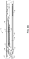
- FIGS. 1-7 depict an exemplary surgical stapling and severing instrument (10) that is sized for insertion, in a non-articulated state as depicted in FIG. 1 , through a trocar cannula to a surgical site in a patient for performing a surgical procedure.
- a trocar may be inserted in a patient's abdomen, between two of the patient's ribs, or elsewhere.
- instrument (10) is used without a trocar.
- instrument (10) may be inserted directly through a thoracotomy or other type of incision.
- Instrument (10) of the present example includes a handle portion (20) connected to a shaft (22).
- articulation joint (11) and/or articulation control (13) are/is constructed and operable in accordance with at least some of the teachings of U.S. Pat. No. 9,186,142, entitled “Surgical Instrument End Effector Articulation Drive with Pinion and Opposing Racks,” issued November 17, 2015 , the disclosure of which is incorporated by reference herein.
- Articulation joint (11) may also be constructed and operable in accordance with at least some of the teachings of U.S. Pat. No. 9,795,379, entitled “Surgical Instrument with Multi-Diameter Shaft,” issued October 24, 2017 , the disclosure of which is incorporated by reference herein.
- Other suitable forms that articulation joint (11) and articulation control (13) may take will be apparent to those of ordinary skill in the art in view of the teachings herein.
- Handle portion (20) includes a pistol grip (24) and a closure trigger (26).
- Closure trigger (26) is pivotable toward pistol grip (24) to cause clamping, or closing, of the anvil (18) toward lower jaw (16) of end effector (12).
- Such closing of anvil (18) is provided through a closure tube (32) and a closure ring (33), which both longitudinally translate relative to handle portion (20) in response to pivoting of closure trigger (26) relative to pistol grip (24).
- Closure tube (32) extends along the length of shaft (22); and closure ring (33) is positioned distal to articulation joint (11).
- Articulation joint (11) is operable to communicate/transmit longitudinal movement from closure tube (32) to closure ring (33).
- Firing beam cap (44) slidably engages a lower surface of lower jaw (16) by having firing beam (14) extend through lower jaw slot (45) (shown in FIG. 4B ) that is formed through lower jaw (16).
- Middle pin (46) slidingly engages a top surface of lower jaw (16), cooperating with firing beam cap (44). Thereby, firing beam (14) affirmatively spaces end effector (12) during firing.
- a wedge sled (41) and a plurality of staple drivers (43) are captured between cartridge body (70) and tray (74), with wedge sled (41) being located proximal to staple drivers (43).
- Wedge sled (41) is movable longitudinally within staple cartridge (37); while staple drivers (43) are movable vertically within staple cartridge (37).
- Staples (47) are also positioned within cartridge body (70), above corresponding staple drivers (43).
- each staple (47) is driven vertically within cartridge body (70) by a staple driver (43) to drive staple (47) out through an associated staple aperture (51).
- wedge sled (41) presents inclined cam surfaces that urge staple drivers (43) upwardly as wedge sled (41) is driven distally through staple cartridge (37).
- staple cartridge (37) is constructed and operable in accordance with at least some of the teachings of U.S. Pat. No. 9,517,065, entitled “Integrated Tissue Positioning and Jaw Alignment Features for Surgical Stapler,” issued December 13, 2016 , the disclosure of which is incorporated by reference herein.
- staple cartridge (37) may be constructed and operable in accordance with at least some of the teachings of U.S. Pat. No. 9,808,248, entitled “Installation Features for Surgical Instrument End Effector Cartridge,” issued November 7, 2017 , the disclosure of which is incorporated by reference herein.
- Other suitable forms that staple cartridge (37) may take will be apparent to those of ordinary skill in the art in view of the teachings herein.
- firing beam (14) is then advanced in engagement with anvil (18) by having upper pin (38) enter longitudinal anvil slot (42).
- a pusher block (80) (shown in FIG. 5 ) is located at the distal end of firing beam (14), and is configured to engage wedge sled (41) such that wedge sled (41) is pushed distally by pusher block (80) as firing beam (14) is advanced distally through staple cartridge (37) when firing trigger (28) is actuated.
- FIGS. 4A-4B depicts firing beam (14) fully distally translated after completing severing and stapling of tissue.
- end effector (12) is withdrawn from the trocar after the first stroke is complete, spent staple cartridge (37) is replaced with a new staple cartridge, and end effector (12) is then again inserted through the trocar to reach the stapling site for further cutting and stapling. This process may be repeated until the desired amount of cuts and staples (47) have been provided.
- Anvil (18) may need to be closed to facilitate insertion and withdrawal through the trocar; and anvil (18) may need to be opened to facilitate replacement of staple cartridge (37).
- firing beam (14) may be configured in accordance with at least some of the teachings of U.S. Pat. No. 8,453,914 , the disclosure of which is incorporated by reference herein; and/or in accordance with at least some of the teachings of U.S. Pat. No. 8,453,914 , the disclosure of which is also incorporated by reference herein.
- Other suitable components, features, and configurations for providing motorization of firing beam (14) will be apparent to those of ordinary skill in the art in view of the teachings herein. It should also be understood that some other versions may provide manual driving of firing beam (14), such that a motor may be omitted.
- firing beam (14) may be actuated in accordance with at least some of the teachings of any other patent/publication reference cited herein.
- end effector (12) it may be desirable to provide the user with better visualization of end effector (12).
- end effector (12) as end effector (12) is inserted into a surgical site, the user may rotate shaft (22) of instrument (10) during the procedure. As a result, end effector (12) also rotates. As end effector (12) rotates, it may be desirable for the user to have visual access to the surgical site. For instance, the user may wish to see the interface or contact between tissue (90) and end effector (12). Since end effector (12) may be rotated about the longitudinal axis (LA) relative to handle portion (20), the user may view the surgical site such that lower jaw (16) of end effector is visible rather than anvil (18).
- LA longitudinal axis
- end effector (12) could be rotated such that when the user views end effector (12), anvil (18) is visible by the user. It may be desirable to provide visibility of the surgical site for the user beyond what is possible in instrument (10) of FIG. 1 . For instance, in the case of some surgical procedures where fluid carrying vessels are transected and stapled, it may be desirable to have visual confirmation that anvil (18) and lower jaw (16) completely cover the vessel to be cut, such that the vessel may be fully cut and stapled in one single actuation. In other words, the user may wish to avoid cutting and stapling only a portion of a vessel.
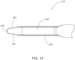
- FIG. 8 depicts an exemplary end effector (212) comprising an anvil (218) and a lower jaw (216). It will be appreciated that end effector (212) may be used in place of end effector (12) of instrument (10). End effector (212) may be integrally formed with instrument (10) or in the alternative may be interchangeable with end effector (12) of instrument (10).
- Anvil (218) as can be seen in FIGS. 8-10 has an elongated shape where the distal portion of anvil (218) angles toward cartridge (237).
- the distal portion of anvil (218) angles toward cartridge (237) such that the distal most tip (219) of anvil (218) extends distally longitudinally further than cartridge (237).
- distal tip (219) may extend to a distance longitudinally equal to cartridge (237) or proximal relative to the distal most point on cartridge (237).
- anvil (218) angles toward cartridge (237) through a gentle slope.
- anvil (218) includes sides (241) that taper as they approach the distal most tip (219) of anvil (218).
- anvil (218) is shaped in FIG. 8 similarly to an inverted ski tip.
- the angled shape of anvil (218) may provide easier insertion of end effector (212) into a surgical site.
- the gentle slope or inverted ski tip shape of anvil (218) may provide an atraumatic tissue deflection surface as anvil (218) contacts or moves through tissue.
- Such atraumatic tissue deflection may include urging tissue (e.g., a large vessel) proximally into the space between anvil (218) and lower jaw (216) as anvil (218) closes toward lower jaw (216).
- anvil (218) may also provide better maneuverability of end effector (212) and better visibility of the distal end of end effector (212) in relation to anatomical structures at the surgical site.
- Other suitable variations of anvil (218) will be apparent to one of ordinary skill in the art in view of the teachings herein.
- Cartridge (237) is operable to hold staples similar to staples (47) shown in FIG. 4A for driving into tissue.
- the distal end of cartridge (237) has a triangular profile.
- the distal end of cartridge (237) comprises an upper tapered surface (239) and a lower tapered surface (238).
- the distal end of cartridge (237) comprises a tapered side surface (243) on each side.
- each tapered side surface (243) of cartridge (237) generally aligns with the taper presented by sides (241) of anvil (218).
- Viewing angle ( ⁇ ) may establish the relative visibility that a user has regarding distal tip (219).
- the user can see in front of distal tip (219) along any line of sight that passes through the intersection of sight line (240) and longitudinal axis (LA) within viewing angle ( ⁇ ).
- viewing angle ( ⁇ ) defines an angle greater than 90 degrees.
- viewing angle ( ⁇ ) defines an angle greater than 135 degrees.
- the tapered shape of anvil (218) may also provide more accessible viewing of distal tip (219) or substantially adjacent distal tip (219).
- the taper of anvil (218) along with lower tapered surface (238) of cartridge (237) may further promote easy insertion of end effector (212) into tissue in an atraumatic manner.
- lower tapered surface (238) and the tapered shape of anvil (218) may provide a lead-in, guiding the rest of end effector (212) into the trocar.
- visibility and maneuverability can be enhanced by the tapered design for both sides (241) of anvil (218) and each side (243) of cartridge (237).
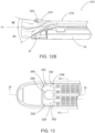
- instrument (310) comprises an end effector (312) having an anvil (318) that has an angled distal tip (319). Furthermore, distal tip (319) of anvil (318) is elastically deformable. In this manner, and as shown best in FIGS. 12A and 12B , angled distal tip (319) is operable to elastically deform from a first angled position to a second position.
- the second position for angled distal tip (319) may be substantially straight in some versions, but may be angled to a degree (e.g., slightly above or slightly below the longitudinal axis (A1)) in other versions.
- end effectors having bent or angled elastic deformable tips also referred to as placement tips, such as those described above with respect to end effectors (312, 412)
- the deformable tips can deflect during use.
- the elastic deformable tip can be located on the anvil, like with anvil (318).
- the elastic deformable tip can be located on the cartridge.
- end effectors (12, 212, 312, 412) described above are discussed as including a lower jaw (16, 216) opposite to the anvil (18, 218, 318), in some versions the end effectors comprise an upper jaw and a lower jaw, where the anvil may be located on either jaw, and the cartridge may be located on either jaw opposite the jaw with the anvil.
- the deflection of the deformable tip changes an angle of the deformable tip relative to a longitudinal axis defined by the jaw with which the deformable tip is located when comparing states when the end effector is in open versus closed states. In some versions that will be shown and described, the deflection of the deformable tip changes an angle of the deformable tip relative to the nose of the cartridge when the end effector is loaded or engages tissue versus when the end effector is not loaded or not engaged with tissue. In some versions that will be shown and described, the placement tip of one of the end effector jaws may adopt certain positions relative to the other of the end effector jaws when in deflected versus non-deflected states. In some versions that will be shown and described, the end effector components are configured with certain placement tip end and/or width profiles. Lastly, in some versions that will be shown and described, the end effector components are configured with certain underside surface configurations and/or gaps.
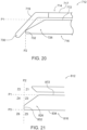
- lower jaw (516) comprises a nose portion (526) at a distal end of lower jaw (516).
- nose portion (526) comprises a top surface (528) that defines a plane having a slope relative to a longitudinal axis (LA2) of lower jaw (516).
- a fifth angle ( ⁇ 1) is defined by the intersection of axis (A3) of placement tip (619) and axis (A4) of nose portion (626).
- fifth angle ( ⁇ 1) is defined by the intersection of a plane extending along underside surface (622) of placement tip (619) and a plane extending along top surface (628) of nose portion (626) when end effector (612) is in an unloaded state.
- an end (630) of placement tip (619) is located proximal to an end (632) of nose portion (626).
- end effector (612) comprises a placement tip (619) extending from the distal end of upper jaw (614).
- Placement tip (619) comprises a third angle ( ⁇ 5) with respect to the axis of body (617) of upper jaw (614), or longitudinal axis (LA3), when end effector (612) is in the closed and unloaded state.
- Placement tip (619) further comprises a fourth angle ( ⁇ 6) with respect to the axis of body (617) of upper jaw (614), when end effector (612) is in the closed position and loaded state, and fourth angle ( ⁇ 6) differs from third angle ( ⁇ 5).
- end effector (612) comprises placement tip (619) having an undeflected state and a deflected state. In the undeflected state placement tip (619) and nose portion (626) define fifth angle ( ⁇ 1), and in the deflected state placement tip (619) and nose portion (626) define sixth angle ( ⁇ 2) that differs from fifth angle ( ⁇ 1).
- placement tip (619) is configured to deflect when end effector (612) is loaded, and such deflection occurs in a manner where end (630) of placement tip (619) changes its relative placement or location with respect to end (632) of nose portion (626) of cartridge (637).
- end (630) is proximal to end (632) when end effector (612) is unloaded such that there is an absence of tissue between upper jaw (614) and lower jaw (616).
- end (630) moves distally such that end (630) is distal to end (632).
- End effector (712) is configured for use with instruments (10, 310) and/or for robotic use as described above.
- End effector (712) comprises upper jaw (714) and lower jaw (716).
- Lower jaw (716) comprises nose portion (726) and end (732).
- Lower jaw (716) further comprises deck (772).
- Upper jaw (714) comprises a body (717) and a placement tip (719).
- Placement tip (719) has a bent or angled configuration and is elastically deformable as described above. Placement tip (719) comprises end (730) at its distal-most portion.
- a first reference plane (P1) is defined by deck (772), and generally extends parallel with a longitudinal axis of lower jaw (716).
- a second reference plane (P2) passes through end (732) of nose portion (726) such that second reference plane (P2) is orthogonal to first reference plane (P1).
- the location or placement of end (732) of placement tip (719) can be shown and described relative to first reference plane (P1) and second reference plane (P2).
- the location or placement of end (730) of placement tip (719) can be described as being proximal to, even with, or distal to end (732) of nose portion (726) of lower jaw (716) as illustrated by second reference plane (P2).
- the location or placement of end (730) of placement tip (719) can be described as being above, even with, or below deck (772) of lower jaw (716) as illustrated by first reference plane (P1).
- end effector (812) is configured for use with instruments (10, 310) and/or for robotic use as described above.
- end effector (812) of FIG. 21 also comprises first reference plane (P1) and second reference plane (P2).
- a third reference plane (P3) is defined by and extends along a bottom surface (834) of lower jaw (816).
- Third reference plane (P3) in the present example is parallel with first reference plane (P1) and also orthogonal to second reference plane (P2).
- a first zone (Z1) is shown as the region above deck (872) of lower jaw (816) (corresponding with first reference plane (P1)) and proximal to end (832) of nose portion (826) (corresponding with second reference plane (P2)).
- a second zone (Z2) is shown as the region above deck (872) of lower jaw (816) (corresponding with first reference plane (P1)) and distal to end (832) of nose portion (826) (corresponding with second reference plane (P2)).
- a third zone (Z3) is shown as the region below deck (872) of lower jaw (816) (corresponding with first reference plane (P1)) yet above bottom surface (834) of lower jaw (816) (corresponding with third reference plane (P3)), and proximal to end (832) of nose portion (826) (corresponding with second reference plane (P2)).
- a fourth zone (Z4) is shown as the region below deck (872) of lower jaw (816) (corresponding with first reference plane (P1)) yet above bottom surface (834) of lower jaw (816) (corresponding with third reference plane (P3)), and distal to end (832) of nose portion (826) (corresponding with second reference plane (P2)).
- a fifth zone (Z5) is shown as the region below bottom surface (834) of lower jaw (816) (corresponding with third reference plane (P3)), and proximal to end (832) of nose portion (826) (corresponding with second reference plane (P2)).
- a sixth zone (Z6) is shown as the region below bottom surface (834) of lower jaw (816) (corresponding with third reference plane (P3)), and distal to end (832) of nose portion (826) (corresponding with second reference plane (P2)).
- End effector (912) is configured for use with instruments (10, 310) and/or for robotic use as described above.
- End effector (912) comprises an upper jaw (914) and a lower jaw (916).
- Upper jaw (914) comprises a body (917) and a placement tip (919).
- placement tip (919) comprises an end (930).
- placement tip (919) has a bent or angled configuration.
- placement tip (919) extends through first zone (Z1), and the location of end (930) of placement tip (919) is in third zone (Z3).
- end effector (912) when end effector (912) is in a closed and loaded state that the location of end (930) of placement tip (919) may deflect yet remain in third zone (Z3).
- placement tip (919) may deflect such that end (930) of placement tip (919) changes its location in the closed and loaded state to another one of the zones.
- End effector (1012) is configured for use with instruments (10, 310) and/or for robotic use as described above.
- End effector (1012) comprises an upper jaw (1014) and a lower jaw (1016).
- Upper jaw (1014) comprises a body (1017) and a placement tip (1019).
- placement tip (1019) comprises an end (1030).
- placement tip (1019) has a curved configuration. With the illustrated configuration, placement tip (1019) extends through first zone (Z1), and the location of end (1030) of placement tip (1019) is in third zone (Z3).
- end effector (1012) when end effector (1012) is in a closed and loaded state that the location of end (1030) of placement tip (1019) may deflect yet remain in third zone (Z3).
- placement tip (1019) may deflect such that end (1030) of placement tip (1019) changes its location in the closed and loaded state to another one of the zones.
- end effector (1112) when end effector (1112) is in a closed and loaded state that the location of end (1130) of placement tip (1119) may deflect yet remain in fourth zone (Z4).
- placement tip (1119) may deflect such that end (1130) of placement tip (1119) changes its location in the closed and loaded state to another one of the zones.
- End effector (1212) is configured for use with instruments (10, 310) and/or for robotic use as described above.
- End effector (1212) comprises an upper jaw (1214) and a lower jaw (1216).
- Upper jaw (1214) comprises a body (1217) and a placement tip (1219).
- placement tip (1219) comprises an end (1230).
- placement tip (1219) has a curved configuration. With the illustrated configuration, placement tip (1219) extends through first, second, third, fourth, and sixth zones (Z1, Z2, Z3, Z4, Z6) and the location of end (1230) of placement tip (1219) is in fifth zone (Z5).
- end effector (1312) when end effector (1312) is in a closed and loaded state that the location of end (1330) of placement tip (1319) may deflect yet remain in sixth zone (Z6).
- placement tip (1319) may deflect such that end (1330) of placement tip (1319) changes its location in the closed and loaded state to another one of the zones.
- placement tip (1519) extends through first zone (Z1) and the location of end (1530) of placement tip (1519) is in third zone (Z3).
- end effector (1512) when end effector (1512) is in a closed and loaded state that the location of end (1530) of placement tip (1519) may deflect yet remain in third zone (Z3).
- placement tip (1519) may deflect such that end (1530) of placement tip (1519) changes its location in the closed and loaded state to another one of the zones.
- end effector (1512) defines a fourth reference plane (P4) based on the offset of body (1517) from step (1591) of placement tip (1519).
- placement tip (1519) comprises an underside surface (1522) that matches the profile of top surface (1528) and deck (1572) of lower jaw (1516).
- Placement tip (1519) defines pivot point (1524) where underside surface (1522) transitions from matching the profile of top surface (1528) of lower jaw (1516) to matching deck (1572) of lower jaw (1516).
- end effector (1512) defines a first distance (D1) as extending from pivot point (1524) proximally to the proximal-most end of step (1591).
- First distance (D1) can be consider as representing the length of placement tip (1519) that overlaps deck (1572) of lower jaw (1516).
- various ways to modify or alter end effector (1512) and first distance (D1) to achieve greater or smaller overlaps of placement tip (1519) and deck (1572) will be apparent to those of ordinary skill in the art.
- both end effectors are shown in closed and unloaded states.
- end effector (612) is shown in a closed and loaded state.
- placement tip (619) deflects such that the distal-most end of placement tip (619) is located mostly in second zone (Z2) with a smaller portion located in fourth zone (Z4).
- various ways to configure an end effector to locate an end of a placement tip in a desired position under various conditions i.e. open/closed and loaded/unloaded, will be apparent to those of ordinary skill in the art.
- FIGS. 23A-23F depict exemplary enlarged placement tip portions that show various distal end profiles for the placement tip.
- an end effector comprises a placement tip (1619).
- placement tip (1619) comprises a distal end (1630) having a round profile.
- Placement tip (1619) is configurable such that it may be positioned on either an upper jaw or lower jaw of the end effector.
- placement tip (1619) is configurable such that it may be part of an anvil or part of a staple cartridge.
- this round distal end profile of placement tip (1619) can be used with any of the placement tips of the end effectors described herein.
- this asymmetric distal end profile of placement tip (2119) can be used with any of the placement tips of the end effectors described herein. While several distal end profiles for placement tips of an end effector have been shown and described above, other distal end profiles for placement tips of an end effector will be apparent to those of ordinary skill in the art in view of the teachings herein.
- FIGS. 24A-24E depict exemplary enlarged placement tip portions that show various width profiles for the placement tip.
- an end effector comprises a placement tip (2219).
- placement tip (2219) comprises distal sides (2229) leading to distal end (2230) where distal sides (2229) define a width profile that is angled.
- Placement tip (2219) is configurable such that it may be positioned on either an upper jaw or lower jaw of the end effector.
- placement tip (2219) is configurable such that it may be part of an anvil or part of a staple cartridge.
- this angled width profile of placement tip (2219) can be used with any of the placement tips of the end effectors described herein.
- FIG. 24C depicts an end effector comprising a placement tip (2419).
- placement tip (2419) comprises distal sides (2429) leading to distal end (2430) where distal sides (2429) define a width profile that is asymmetric such that distal sides (2429) are not symmetrically oriented, and in this instance are angled to varying degrees.
- Placement tip (2419) is configurable such that it may be positioned on either an upper jaw or lower jaw of the end effector.
- placement tip (2419) is configurable such that it may be part of an anvil or part of a staple cartridge. In view of the teachings herein, it will be apparent to those of ordinary skill in the art that this asymmetric width profile of placement tip (2419) can be used with any of the placement tips of the end effectors described herein.
- FIG. 24D depicts an end effector comprising a placement tip (2519).
- placement tip (2519) comprises distal sides (2529) leading to distal end (2530) where distal sides (2529) define a width profile that is scalloped with distal end (2530) centered along the longitudinal axis of placement tip (2519).
- one of distal sides (2529) has a curvature that is concave while the other has a curvature that is convex.
- Placement tip (2519) is configurable such that it may be positioned on either an upper jaw or lower jaw of the end effector.
- FIG. 24E depicts an end effector comprising a placement tip (2619).
- placement tip (2619) comprises distal sides (2629) leading to distal end (2630) where distal sides (2629) define a width profile having bump-outs or lateral protrusions (2631) on each side.
- a jaw (2616) of end effector opposite placement tip (2619) is shown in phantom.
- the bump-outs (2631) extend outward from jaw (2616), whereas the remaining width of placement tip (2619) is narrower than the width of jaw (2616).
- bump-outs (2631) are not required to extend out from the width of jaw (2616) in all versions.
- placement tip (2619) is configured to provide resistance when moving the instrument with the end effector and placement tip (2619) in and out of a site. Additionally, bump-outs (2631) are configured to dilate an aperture larger when placement tip (2619) passes therethrough.
- Placement tip (2619) is configurable such that it may be positioned on either an upper jaw or lower jaw of the end effector. Furthermore, placement tip (2619) is configurable such that it may be part of an anvil or part of a staple cartridge. In view of the teachings herein, it will be apparent to those of ordinary skill in the art that this width profile of placement tip (2619) having bump-outs (2631) on each side can be used with any of the placement tips of the end effectors described herein.
- FIG. 25 depicts an enlarged top view of a placement tip (2719) of an end effector, with the placement tip (2719) having a distal end (2730) with an angled and pointed profile and with the placement tip (2719) having distal sides (2729) defining a width profile that angled.
- placement tip (2719) illustrates a combination of the angled and pointed distal end profile of placement tip (1719) of FIG. 23B , with the angled width profile of placement tip (2219) of FIG. 24A .
- various combinations of distal end profiles and width profiles will be apparent to those of ordinary skill in the art.
- Placement tip (2719) further illustrates the relationship between the profile at distal end (2730) compared to the width profile defined by distal sides (2729).
- placement tips extend from a body of one of an upper jaw or lower jaw of an end effector.
- placement tip (2719) is understood to have a shorter longitudinal dimension, or length, than the body of the jaw from which it extends.
- placement tip (2719) can be understood to have a length characterized by the sum of a first length (L1) and a second length (L2).
- first length (L1) is substantially greater than second length (L2).
- second length (L2) is substantially greater than first length (L2).
- Placement tip (2719) further illustrates an example where a plane defined by one of symmetrical distal sides (2729) in combination with another plane defined by one of a proximal sides (2733), form an angle ( ⁇ 1).
- angle ( ⁇ 1) increases as the width profile defined by distal sides (2729) becomes more angular or steeper.
- angle ( ⁇ 1) decreases.
- Placement tip (2719) also illustrates an example where a plane defined tangent to the distal-most portion of distal end (2730) in combination with a plane defined by one of sides (2735) of distal end (2730), forms an angle ( ⁇ 2).
- angle ( ⁇ 2) increases as the sides (2735) of distal end (2730) become more angular or steeper.
- angle ( ⁇ 2) decreases.
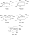
- FIG. 26A depicts end effector (2812) comprising upper jaw (2814) and lower jaw (2816).
- Upper jaw (2814) comprises body (2817) and placement tip (2819) extending distally from body (2817).
- Placement tip (2819) has a bent or angled configuration and comprises an underside surface (2822) that is flat.
- underside surface (2822) is also parallel with a top surface (2828) on nose portion (2826) of lower jaw (2816). In this manner, when end effector (2812) is closed and unloaded, underside surface (2822) can contact top surface (2828).
- FIG. 26B depicts end effector (2912) comprising upper jaw (2914) and lower jaw (2916).
- Upper jaw (2914) comprises body (2917) and placement tip (2919) extending distally from body (2917).
- Placement tip (2919) has a curved configuration and comprises underside surface (2922) that is curved.
- lower jaw (2916) comprises nose portion (2926) with a tapered top surface (2928). The curvature of underside surface (2922) in combination with the tapered top surface (2928) of nose portion (2926) provides placement tip (2919) with point contact when end effector (2912) is closed and unloaded, as opposed to greater contact area as with end effector (2812) shown and described above.
- FIG. 26C depicts end effector (3012) comprising upper jaw (3014) and lower jaw (3016).
- Upper jaw (3014) comprises body (3017) and placement tip (3019) extending distally from body (3017).
- Placement tip (3019) has a straight configuration and comprises an underside surface (3022) that is straight.
- Placement tip (3019) is configured as elastically deformable as described above. In this manner, underside surface (3022) of placement tip (3019) extends along the same plane as an underside surface (3020) of body (3017) of upper jaw (3014).
- lower jaw (3016) comprises nose portion (3026) with a tapered top surface (3028). The straight configuration of underside surface (3022), in combination with the tapered top surface (3028) of nose portion (3026), eliminates placement tip (3019) contact with tapered top surface (3028) when end effector (3012) is closed and unloaded.
- FIG. 26D depicts end effector (3112) comprising upper jaw (3114) and lower jaw (3116).
- Upper jaw (3114) comprises body (3117) and placement tip (3119) extending distally from body (3117).
- Placement tip (3119) has a curved configuration and comprises an underside surface (3122) that is multi-angled. Placement tip (3119) is configured as elastically deformable as described above.
- lower jaw (3116) comprises nose portion (3126) with a tapered top surface (3128). The multi-angled nature of underside surface (3122) in combination with the tapered top surface (3128) of nose portion (3126) provides placement tip (3119) with point contact when end effector (3112) is closed and unloaded, as opposed to greater contact area as with end effector (3112) shown and described above.
- FIG. 26E depicts end effector (3212) comprising upper jaw (3214) having dual positions and lower jaw (3216).
- Upper jaw (3214) comprises body (3217) and placement tip (3219) extending distally from body (3217).
- Placement tip (3219) has a bent or angled configuration when end effector (3212) is open and unloaded as shown in phantom in FIG. 26E .
- Placement tip (3219) comprises an underside surface (3222) that includes a curved protrusion (3231). Placement tip (3219) is configured as elastically deformable as described above.
- lower jaw (3216) comprises nose portion (3226) with a tapered top surface (3228) as well as deck (3272).
- the curved protrusion (3231) of underside surface (3222) of placement tip (3219) is configured to act as a pivot structure such that placement tip (3219) pivots from its bent or angled orientation shown in phantom to a straight, or at least less bent or angled, orientation in response to curved protrusion (3231) contacting a structure such as deck (3272) when end effector (3212) is closed and without tissue between jaws (3214, 3216), or tissue when end effector (3212) is closed and loaded with tissue between jaws (3214, 3216).
- the various end effectors described herein provide visualization and guidance features as described above. Additionally, the ability of the placement tips to deflect or elastically deform can provide benefits in use during procedure where marching may be required or beneficial. In addition to the ability of the placement tips to elastically deform, the presence or absence of a gap between the placement tip and the opposite jaw's surface can impact visualization and marching. For instance, in some versions with little or no gap, the ability of the placement tip to elastically deform enables use of the end effector in marching procedures.
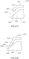
- FIGS. 27A and 27B depict portions of end effectors that illustrate exemplary gaps and their configurations.
- FIG. 27A depicts an enlarged side view of a distal portion of an end effector (3312), showing a gap (3340) between a placement tip (3319) of an upper jaw (3314) and a nose portion (3326) of a lower jaw (3316).
- end effector (3312) is shown in a closed and unloaded state.
- Placement tip (3319) comprises underside surface (3322) that is generally parallel with a top surface (3320) of nose portion (3326) of lower jaw (3316).
- gap (3340) is generally of uniform size along underside surface (3322) of placement tip (3319) and top surface (3320) of nose portion (3326).
- end effector (3312) is configured for use in procedures where marching is desired.
- FIG. 27B depicts an enlarged side view of a distal portion of an end effector (3412), showing a gap (3440) between a distal end (3430) of a placement tip (3419) of an upper jaw (3414) and a nose portion (3426) of a lower jaw (3416).
- Placement tip (3419) is bent or angled and with end effector (3412) closed and unloaded as shown, end (3430) contacts or nearly contacts a top surface (3420) of nose portion (3426) of lower jaw (3416).
- gap (3440) is either very small, or in the case where jaws (3414, 3416) touch, gap (3440) is absent altogether.
- gap (3440) increases in size as gap (3440) extends proximally.
- end effector (3412) is configured for use in procedures where marching is desired.
- An apparatus comprises a body, a shaft extending from the body, wherein the shaft defines a longitudinal axis, and an end effector in communication with the shaft, wherein the end effector is operable to compress, staple, and cut tissue.
- the end effector comprises a pair of jaws, wherein at least one of the jaws is operable to move relative to the other jaw between an open position and a closed position, a cartridge configured to hold one or more staples, wherein the cartridge selectively connects with a first jaw of the pair of jaws, an anvil configured to be contacted by the one or more staples of the cartridge, wherein a second jaw of the pair of jaws comprises the anvil, and a placement tip that is elastically deformable.
- the placement tip extends distally from a select one of the pair of jaws, wherein the placement tip defines a first angle with respect to an axis of the select one of the jaws from which the placement tip extends when the end effector is in the open position, and a second angle with respect the axis of the select one of the jaws from which the placement tip extends when the end effector is in a closed position.
- the second angle differs from the first angle.
- Example 1 The apparatus of Example 1, wherein the placement tip extends distally from the anvil.
- the placement tip comprises a shape selected from the group comprising straight, curved, bent, angled, and combinations thereof.
- the placement tip extends distally from a select one of the pair of jaws, wherein the placement tip defines a first angle with respect to a surface of a portion of the jaw opposite to the select one of the jaws from which the placement tip extends when the placement tip is in a first undeflected state, and a second angle with respect to the surface of the portion of the jaw opposite to the select one of the jaws from which the placement tip extends when the placement tip is in a second deflected state.
- the second angle differs from the first angle.
Landscapes
- Health & Medical Sciences (AREA)
- Life Sciences & Earth Sciences (AREA)
- Surgery (AREA)
- Heart & Thoracic Surgery (AREA)
- Engineering & Computer Science (AREA)
- Biomedical Technology (AREA)
- Nuclear Medicine, Radiotherapy & Molecular Imaging (AREA)
- Medical Informatics (AREA)
- Molecular Biology (AREA)
- Animal Behavior & Ethology (AREA)
- General Health & Medical Sciences (AREA)
- Public Health (AREA)
- Veterinary Medicine (AREA)
- Surgical Instruments (AREA)
Applications Claiming Priority (2)
| Application Number | Priority Date | Filing Date | Title |
|---|---|---|---|
| US16/035,856 US11564684B2 (en) | 2017-02-17 | 2018-07-16 | Surgical stapling end effector component with tip having varying bend angle |
| EP19186224.2A EP3597117B1 (de) | 2018-07-16 | 2019-07-15 | Endeffektorkomponente für chirurgisches klammergerät mit spitze mit variierendem biegewinkel |
Related Parent Applications (1)
| Application Number | Title | Priority Date | Filing Date |
|---|---|---|---|
| EP19186224.2A Division EP3597117B1 (de) | 2018-07-16 | 2019-07-15 | Endeffektorkomponente für chirurgisches klammergerät mit spitze mit variierendem biegewinkel |
Publications (3)
| Publication Number | Publication Date |
|---|---|
| EP4393413A2 true EP4393413A2 (de) | 2024-07-03 |
| EP4393413A3 EP4393413A3 (de) | 2024-09-04 |
| EP4393413B1 EP4393413B1 (de) | 2026-04-22 |
Family
ID=67297013
Family Applications (2)
| Application Number | Title | Priority Date | Filing Date |
|---|---|---|---|
| EP24175364.9A Active EP4393413B1 (de) | 2018-07-16 | 2019-07-15 | Endeffektorkomponente für chirurgisches klammergerät mit spitze mit variierendem biegewinkel |
| EP19186224.2A Active EP3597117B1 (de) | 2018-07-16 | 2019-07-15 | Endeffektorkomponente für chirurgisches klammergerät mit spitze mit variierendem biegewinkel |
Family Applications After (1)
| Application Number | Title | Priority Date | Filing Date |
|---|---|---|---|
| EP19186224.2A Active EP3597117B1 (de) | 2018-07-16 | 2019-07-15 | Endeffektorkomponente für chirurgisches klammergerät mit spitze mit variierendem biegewinkel |
Country Status (4)
| Country | Link |
|---|---|
| EP (2) | EP4393413B1 (de) |
| JP (1) | JP7494162B2 (de) |
| CN (1) | CN112672699B (de) |
| WO (1) | WO2020016721A1 (de) |
Families Citing this family (1)
| Publication number | Priority date | Publication date | Assignee | Title |
|---|---|---|---|---|
| CN119867849A (zh) * | 2025-01-20 | 2025-04-25 | 江苏科曼医疗科技有限公司 | 抵钉座、切换工具和外科器械 |
Citations (49)
| Publication number | Priority date | Publication date | Assignee | Title |
|---|---|---|---|---|
| US4805823A (en) | 1988-03-18 | 1989-02-21 | Ethicon, Inc. | Pocket configuration for internal organ staplers |
| US5415334A (en) | 1993-05-05 | 1995-05-16 | Ethicon Endo-Surgery | Surgical stapler and staple cartridge |
| US5465895A (en) | 1994-02-03 | 1995-11-14 | Ethicon Endo-Surgery, Inc. | Surgical stapler instrument |
| US5597107A (en) | 1994-02-03 | 1997-01-28 | Ethicon Endo-Surgery, Inc. | Surgical stapler instrument |
| US5632432A (en) | 1994-12-19 | 1997-05-27 | Ethicon Endo-Surgery, Inc. | Surgical instrument |
| US5704534A (en) | 1994-12-19 | 1998-01-06 | Ethicon Endo-Surgery, Inc. | Articulation assembly for surgical instruments |
| US5792135A (en) | 1996-05-20 | 1998-08-11 | Intuitive Surgical, Inc. | Articulated surgical instrument for performing minimally invasive surgery with enhanced dexterity and sensitivity |
| US5814055A (en) | 1995-09-19 | 1998-09-29 | Ethicon Endo-Surgery, Inc. | Surgical clamping mechanism |
| US5817084A (en) | 1993-05-14 | 1998-10-06 | Sri International | Remote center positioning device with flexible drive |
| US5878193A (en) | 1992-08-10 | 1999-03-02 | Computer Motion, Inc. | Automated endoscope system for optimal positioning |
| US6231565B1 (en) | 1997-06-18 | 2001-05-15 | United States Surgical Corporation | Robotic arm DLUs for performing surgical tasks |
| US6364888B1 (en) | 1996-09-09 | 2002-04-02 | Intuitive Surgical, Inc. | Alignment of master and slave in a minimally invasive surgical apparatus |
| US6783524B2 (en) | 2001-04-19 | 2004-08-31 | Intuitive Surgical, Inc. | Robotic surgical tool with ultrasound cauterizing and cutting instrument |
| US6978921B2 (en) | 2003-05-20 | 2005-12-27 | Ethicon Endo-Surgery, Inc. | Surgical stapling instrument incorporating an E-beam firing mechanism |
| US7143923B2 (en) | 2003-05-20 | 2006-12-05 | Ethicon Endo-Surgery, Inc. | Surgical stapling instrument having a firing lockout for an unclosed anvil |
| US7303108B2 (en) | 2003-09-29 | 2007-12-04 | Ethicon Endo-Surgery, Inc. | Surgical stapling instrument incorporating a multi-stroke firing mechanism with a flexible rack |
| US7367485B2 (en) | 2004-06-30 | 2008-05-06 | Ethicon Endo-Surgery, Inc. | Surgical stapling instrument incorporating a multistroke firing mechanism having a rotary transmission |
| US7380696B2 (en) | 2003-05-20 | 2008-06-03 | Ethicon Endo-Surgery, Inc. | Articulating surgical stapling instrument incorporating a two-piece E-beam firing mechanism |
| US7380695B2 (en) | 2003-05-20 | 2008-06-03 | Ethicon Endo-Surgery, Inc. | Surgical stapling instrument having a single lockout mechanism for prevention of firing |
| US7404508B2 (en) | 2005-07-26 | 2008-07-29 | Ethicon Endo-Surgery, Inc. | Surgical stapling and cutting device |
| US7434715B2 (en) | 2003-09-29 | 2008-10-14 | Ethicon Endo-Surgery, Inc. | Surgical stapling instrument having multistroke firing with opening lockout |
| US7524320B2 (en) | 1998-12-08 | 2009-04-28 | Intuitive Surgical, Inc. | Mechanical actuator interface system for robotic surgical tools |
| US7644848B2 (en) | 2006-01-31 | 2010-01-12 | Ethicon Endo-Surgery, Inc. | Electronic lockouts and surgical instrument including same |
| US7691098B2 (en) | 2001-06-29 | 2010-04-06 | Intuitive Surgical, Inc. | Platform link wrist mechanism |
| US7721930B2 (en) | 2006-11-10 | 2010-05-25 | Thicon Endo-Surgery, Inc. | Disposable cartridge with adhesive for use with a stapling device |
| US7806891B2 (en) | 1998-11-20 | 2010-10-05 | Intuitive Surgical Operations, Inc. | Repositioning and reorientation of master/slave relationship in minimally invasive telesurgery |
| US8210411B2 (en) | 2008-09-23 | 2012-07-03 | Ethicon Endo-Surgery, Inc. | Motor-driven surgical cutting instrument |
| US8408439B2 (en) | 2007-06-22 | 2013-04-02 | Ethicon Endo-Surgery, Inc. | Surgical stapling instrument with an articulatable end effector |
| US8453914B2 (en) | 2009-12-24 | 2013-06-04 | Ethicon Endo-Surgery, Inc. | Motor-driven surgical cutting instrument with electric actuator directional control assembly |
| US8479969B2 (en) | 2007-01-10 | 2013-07-09 | Ethicon Endo-Surgery, Inc. | Drive interface for operably coupling a manipulatable surgical tool to a robot |
| US8573465B2 (en) | 2008-02-14 | 2013-11-05 | Ethicon Endo-Surgery, Inc. | Robotically-controlled surgical end effector system with rotary actuated closure systems |
| US8573461B2 (en) | 2008-02-14 | 2013-11-05 | Ethicon Endo-Surgery, Inc. | Surgical stapling instruments with cam-driven staple deployment arrangements |
| US8602288B2 (en) | 2008-09-23 | 2013-12-10 | Ethicon Endo-Surgery. Inc. | Robotically-controlled motorized surgical end effector system with rotary actuated closure systems having variable actuation speeds |
| US8616431B2 (en) | 2007-06-04 | 2013-12-31 | Ethicon Endo-Surgery, Inc. | Shiftable drive interface for robotically-controlled surgical tool |
| US8783541B2 (en) | 2003-05-20 | 2014-07-22 | Frederick E. Shelton, IV | Robotically-controlled surgical end effector system |
| US8800838B2 (en) | 2005-08-31 | 2014-08-12 | Ethicon Endo-Surgery, Inc. | Robotically-controlled cable-based surgical end effectors |
| US20140239037A1 (en) | 2013-02-28 | 2014-08-28 | Ethicon Endo-Surgery, Inc. | Staple forming features for surgical stapling instrument |
| US8820605B2 (en) | 2006-01-31 | 2014-09-02 | Ethicon Endo-Surgery, Inc. | Robotically-controlled surgical instruments |
| US8844789B2 (en) | 2006-01-31 | 2014-09-30 | Ethicon Endo-Surgery, Inc. | Automated end effector component reloading system for use with a robotic system |
| US9186142B2 (en) | 2013-02-28 | 2015-11-17 | Ethicon Endo-Surgery, Inc. | Surgical instrument end effector articulation drive with pinion and opposing racks |
| US9301759B2 (en) | 2006-03-23 | 2016-04-05 | Ethicon Endo-Surgery, Llc | Robotically-controlled surgical instrument with selectively articulatable end effector |
| US9517065B2 (en) | 2013-02-28 | 2016-12-13 | Ethicon Endo-Surgery, Llc | Integrated tissue positioning and jaw alignment features for surgical stapler |
| US20170086823A1 (en) | 2015-09-29 | 2017-03-30 | Ethicon Endo-Surgery, Llc | Surgical stapling instrument with shaft release, powered firing, and powered articulation |
| US9622746B2 (en) | 2013-02-28 | 2017-04-18 | Ethicon Endo-Surgery, Llc | Distal tip features for end effector of surgical instrument |
| US9717497B2 (en) | 2013-02-28 | 2017-08-01 | Ethicon Llc | Lockout feature for movable cutting member of surgical instrument |
| US9795379B2 (en) | 2013-02-28 | 2017-10-24 | Ethicon Llc | Surgical instrument with multi-diameter shaft |
| US9808248B2 (en) | 2013-02-28 | 2017-11-07 | Ethicon Llc | Installation features for surgical instrument end effector cartridge |
| US9839421B2 (en) | 2013-02-28 | 2017-12-12 | Ethicon Llc | Jaw closure feature for end effector of surgical instrument |
| US9913642B2 (en) | 2014-03-26 | 2018-03-13 | Ethicon Llc | Surgical instrument comprising a sensor system |
Family Cites Families (7)
| Publication number | Priority date | Publication date | Assignee | Title |
|---|---|---|---|---|
| US20040243151A1 (en) * | 2003-04-29 | 2004-12-02 | Demmy Todd L. | Surgical stapling device with dissecting tip |
| US8136711B2 (en) * | 2006-09-08 | 2012-03-20 | Tyco Healthcare Group Lp | Dissection tip and introducer for surgical instrument |
| US8403196B2 (en) * | 2006-09-08 | 2013-03-26 | Covidien Lp | Dissection tip and introducer for surgical instrument |
| US9936952B2 (en) * | 2014-02-03 | 2018-04-10 | Covidien Lp | Introducer assembly for a surgical fastener applying apparatus |
| WO2017083129A1 (en) * | 2015-11-13 | 2017-05-18 | Intuitive Surgical Operations, Inc. | Stapler anvil with compliant tip |
| US10639035B2 (en) * | 2016-12-21 | 2020-05-05 | Ethicon Llc | Surgical stapling instruments and replaceable tool assemblies thereof |
| US10828031B2 (en) * | 2017-02-17 | 2020-11-10 | Ethicon Llc | Surgical stapler with elastically deformable tip |
-
2019
- 2019-07-12 WO PCT/IB2019/055980 patent/WO2020016721A1/en not_active Ceased
- 2019-07-12 JP JP2021502529A patent/JP7494162B2/ja active Active
- 2019-07-12 CN CN201980059137.5A patent/CN112672699B/zh active Active
- 2019-07-15 EP EP24175364.9A patent/EP4393413B1/de active Active
- 2019-07-15 EP EP19186224.2A patent/EP3597117B1/de active Active
Patent Citations (51)
| Publication number | Priority date | Publication date | Assignee | Title |
|---|---|---|---|---|
| US4805823A (en) | 1988-03-18 | 1989-02-21 | Ethicon, Inc. | Pocket configuration for internal organ staplers |
| US5878193A (en) | 1992-08-10 | 1999-03-02 | Computer Motion, Inc. | Automated endoscope system for optimal positioning |
| US5415334A (en) | 1993-05-05 | 1995-05-16 | Ethicon Endo-Surgery | Surgical stapler and staple cartridge |
| US5817084A (en) | 1993-05-14 | 1998-10-06 | Sri International | Remote center positioning device with flexible drive |
| US5465895A (en) | 1994-02-03 | 1995-11-14 | Ethicon Endo-Surgery, Inc. | Surgical stapler instrument |
| US5597107A (en) | 1994-02-03 | 1997-01-28 | Ethicon Endo-Surgery, Inc. | Surgical stapler instrument |
| US5632432A (en) | 1994-12-19 | 1997-05-27 | Ethicon Endo-Surgery, Inc. | Surgical instrument |
| US5673840A (en) | 1994-12-19 | 1997-10-07 | Ethicon Endo-Surgery, Inc. | Surgical instrument |
| US5704534A (en) | 1994-12-19 | 1998-01-06 | Ethicon Endo-Surgery, Inc. | Articulation assembly for surgical instruments |
| US5814055A (en) | 1995-09-19 | 1998-09-29 | Ethicon Endo-Surgery, Inc. | Surgical clamping mechanism |
| US5792135A (en) | 1996-05-20 | 1998-08-11 | Intuitive Surgical, Inc. | Articulated surgical instrument for performing minimally invasive surgery with enhanced dexterity and sensitivity |
| US6364888B1 (en) | 1996-09-09 | 2002-04-02 | Intuitive Surgical, Inc. | Alignment of master and slave in a minimally invasive surgical apparatus |
| US6231565B1 (en) | 1997-06-18 | 2001-05-15 | United States Surgical Corporation | Robotic arm DLUs for performing surgical tasks |
| US7806891B2 (en) | 1998-11-20 | 2010-10-05 | Intuitive Surgical Operations, Inc. | Repositioning and reorientation of master/slave relationship in minimally invasive telesurgery |
| US7524320B2 (en) | 1998-12-08 | 2009-04-28 | Intuitive Surgical, Inc. | Mechanical actuator interface system for robotic surgical tools |
| US6783524B2 (en) | 2001-04-19 | 2004-08-31 | Intuitive Surgical, Inc. | Robotic surgical tool with ultrasound cauterizing and cutting instrument |
| US7691098B2 (en) | 2001-06-29 | 2010-04-06 | Intuitive Surgical, Inc. | Platform link wrist mechanism |
| US6978921B2 (en) | 2003-05-20 | 2005-12-27 | Ethicon Endo-Surgery, Inc. | Surgical stapling instrument incorporating an E-beam firing mechanism |
| US7380696B2 (en) | 2003-05-20 | 2008-06-03 | Ethicon Endo-Surgery, Inc. | Articulating surgical stapling instrument incorporating a two-piece E-beam firing mechanism |
| US7380695B2 (en) | 2003-05-20 | 2008-06-03 | Ethicon Endo-Surgery, Inc. | Surgical stapling instrument having a single lockout mechanism for prevention of firing |
| US8783541B2 (en) | 2003-05-20 | 2014-07-22 | Frederick E. Shelton, IV | Robotically-controlled surgical end effector system |
| US7143923B2 (en) | 2003-05-20 | 2006-12-05 | Ethicon Endo-Surgery, Inc. | Surgical stapling instrument having a firing lockout for an unclosed anvil |
| US7000818B2 (en) | 2003-05-20 | 2006-02-21 | Ethicon, Endo-Surger, Inc. | Surgical stapling instrument having separate distinct closing and firing systems |
| US7434715B2 (en) | 2003-09-29 | 2008-10-14 | Ethicon Endo-Surgery, Inc. | Surgical stapling instrument having multistroke firing with opening lockout |
| US7303108B2 (en) | 2003-09-29 | 2007-12-04 | Ethicon Endo-Surgery, Inc. | Surgical stapling instrument incorporating a multi-stroke firing mechanism with a flexible rack |
| US7367485B2 (en) | 2004-06-30 | 2008-05-06 | Ethicon Endo-Surgery, Inc. | Surgical stapling instrument incorporating a multistroke firing mechanism having a rotary transmission |
| US7404508B2 (en) | 2005-07-26 | 2008-07-29 | Ethicon Endo-Surgery, Inc. | Surgical stapling and cutting device |
| US8800838B2 (en) | 2005-08-31 | 2014-08-12 | Ethicon Endo-Surgery, Inc. | Robotically-controlled cable-based surgical end effectors |
| US8844789B2 (en) | 2006-01-31 | 2014-09-30 | Ethicon Endo-Surgery, Inc. | Automated end effector component reloading system for use with a robotic system |
| US8820605B2 (en) | 2006-01-31 | 2014-09-02 | Ethicon Endo-Surgery, Inc. | Robotically-controlled surgical instruments |
| US7644848B2 (en) | 2006-01-31 | 2010-01-12 | Ethicon Endo-Surgery, Inc. | Electronic lockouts and surgical instrument including same |
| US9301759B2 (en) | 2006-03-23 | 2016-04-05 | Ethicon Endo-Surgery, Llc | Robotically-controlled surgical instrument with selectively articulatable end effector |
| US7721930B2 (en) | 2006-11-10 | 2010-05-25 | Thicon Endo-Surgery, Inc. | Disposable cartridge with adhesive for use with a stapling device |
| US8479969B2 (en) | 2007-01-10 | 2013-07-09 | Ethicon Endo-Surgery, Inc. | Drive interface for operably coupling a manipulatable surgical tool to a robot |
| US8616431B2 (en) | 2007-06-04 | 2013-12-31 | Ethicon Endo-Surgery, Inc. | Shiftable drive interface for robotically-controlled surgical tool |
| US8408439B2 (en) | 2007-06-22 | 2013-04-02 | Ethicon Endo-Surgery, Inc. | Surgical stapling instrument with an articulatable end effector |
| US8573461B2 (en) | 2008-02-14 | 2013-11-05 | Ethicon Endo-Surgery, Inc. | Surgical stapling instruments with cam-driven staple deployment arrangements |
| US8573465B2 (en) | 2008-02-14 | 2013-11-05 | Ethicon Endo-Surgery, Inc. | Robotically-controlled surgical end effector system with rotary actuated closure systems |
| US8210411B2 (en) | 2008-09-23 | 2012-07-03 | Ethicon Endo-Surgery, Inc. | Motor-driven surgical cutting instrument |
| US8602288B2 (en) | 2008-09-23 | 2013-12-10 | Ethicon Endo-Surgery. Inc. | Robotically-controlled motorized surgical end effector system with rotary actuated closure systems having variable actuation speeds |
| US8453914B2 (en) | 2009-12-24 | 2013-06-04 | Ethicon Endo-Surgery, Inc. | Motor-driven surgical cutting instrument with electric actuator directional control assembly |
| US9517065B2 (en) | 2013-02-28 | 2016-12-13 | Ethicon Endo-Surgery, Llc | Integrated tissue positioning and jaw alignment features for surgical stapler |
| US9186142B2 (en) | 2013-02-28 | 2015-11-17 | Ethicon Endo-Surgery, Inc. | Surgical instrument end effector articulation drive with pinion and opposing racks |
| US20140239037A1 (en) | 2013-02-28 | 2014-08-28 | Ethicon Endo-Surgery, Inc. | Staple forming features for surgical stapling instrument |
| US9622746B2 (en) | 2013-02-28 | 2017-04-18 | Ethicon Endo-Surgery, Llc | Distal tip features for end effector of surgical instrument |
| US9717497B2 (en) | 2013-02-28 | 2017-08-01 | Ethicon Llc | Lockout feature for movable cutting member of surgical instrument |
| US9795379B2 (en) | 2013-02-28 | 2017-10-24 | Ethicon Llc | Surgical instrument with multi-diameter shaft |
| US9808248B2 (en) | 2013-02-28 | 2017-11-07 | Ethicon Llc | Installation features for surgical instrument end effector cartridge |
| US9839421B2 (en) | 2013-02-28 | 2017-12-12 | Ethicon Llc | Jaw closure feature for end effector of surgical instrument |
| US9913642B2 (en) | 2014-03-26 | 2018-03-13 | Ethicon Llc | Surgical instrument comprising a sensor system |
| US20170086823A1 (en) | 2015-09-29 | 2017-03-30 | Ethicon Endo-Surgery, Llc | Surgical stapling instrument with shaft release, powered firing, and powered articulation |
Also Published As
| Publication number | Publication date |
|---|---|
| WO2020016721A1 (en) | 2020-01-23 |
| EP3597117C0 (de) | 2024-05-15 |
| JP2021530304A (ja) | 2021-11-11 |
| EP3597117A1 (de) | 2020-01-22 |
| JP7494162B2 (ja) | 2024-06-03 |
| EP3597117B1 (de) | 2024-05-15 |
| CN112672699B (zh) | 2024-06-18 |
| EP4393413A3 (de) | 2024-09-04 |
| BR112021000557A2 (pt) | 2021-04-06 |
| CN112672699A (zh) | 2021-04-16 |
| EP4393413B1 (de) | 2026-04-22 |
Similar Documents
| Publication | Publication Date | Title |
|---|---|---|
| US11992212B2 (en) | Surgical stapling end effector component with tip having varying bend angle | |
| US12446876B2 (en) | Method of surgical stapling with end effector component having a curved tip | |
| US20250169816A1 (en) | Method of surgical stapling with end effector component having a curved tip | |
| EP3363384B1 (de) | Chirurgisches klammergerät mit kooperierenden funktionen distalen spitzen am amboss und klammermagazin | |
| EP3363378B1 (de) | Chirurgisches klammergerät mit gebogener ambossspitze, abgewinkelter klammerpatronenspitze und gewebegreifmerkmalen | |
| US10828031B2 (en) | Surgical stapler with elastically deformable tip | |
| EP3363385B1 (de) | Chirurgisches klammergerät mit einführbarer distaler ambossspitze | |
| US11103244B2 (en) | Surgical stapling end effector jaw with tip deflecting toward other jaw | |
| EP4393413B1 (de) | Endeffektorkomponente für chirurgisches klammergerät mit spitze mit variierendem biegewinkel | |
| EP3597118A1 (de) | Verfahren zum chirurgischen klammern mit endeffektorkomponente mit einer gekrümmten spitze | |
| EP3597121B1 (de) | Endeffektorbacke für chirurgisches klammergerät mit zur anderen backe hin ablenkender spitze |
Legal Events
| Date | Code | Title | Description |
|---|---|---|---|
| PUAI | Public reference made under article 153(3) epc to a published international application that has entered the european phase |
Free format text: ORIGINAL CODE: 0009012 |
|
| STAA | Information on the status of an ep patent application or granted ep patent |
Free format text: STATUS: THE APPLICATION HAS BEEN PUBLISHED |
|
| AC | Divisional application: reference to earlier application |
Ref document number: 3597117 Country of ref document: EP Kind code of ref document: P |
|
| AK | Designated contracting states |
Kind code of ref document: A2 Designated state(s): AL AT BE BG CH CY CZ DE DK EE ES FI FR GB GR HR HU IE IS IT LI LT LU LV MC MK MT NL NO PL PT RO RS SE SI SK SM TR |
|
| PUAL | Search report despatched |
Free format text: ORIGINAL CODE: 0009013 |
|
| AK | Designated contracting states |
Kind code of ref document: A3 Designated state(s): AL AT BE BG CH CY CZ DE DK EE ES FI FR GB GR HR HU IE IS IT LI LT LU LV MC MK MT NL NO PL PT RO RS SE SI SK SM TR |
|
| RIC1 | Information provided on ipc code assigned before grant |
Ipc: A61B 17/072 20060101AFI20240730BHEP |
|
| STAA | Information on the status of an ep patent application or granted ep patent |
Free format text: STATUS: REQUEST FOR EXAMINATION WAS MADE |
|
| 17P | Request for examination filed |
Effective date: 20250304 |
|
| GRAP | Despatch of communication of intention to grant a patent |
Free format text: ORIGINAL CODE: EPIDOSNIGR1 |
|
| STAA | Information on the status of an ep patent application or granted ep patent |
Free format text: STATUS: GRANT OF PATENT IS INTENDED |
|
| INTG | Intention to grant announced |
Effective date: 20250820 |
|
| GRAS | Grant fee paid |
Free format text: ORIGINAL CODE: EPIDOSNIGR3 |
|
| GRAA | (expected) grant |
Free format text: ORIGINAL CODE: 0009210 |
|
| STAA | Information on the status of an ep patent application or granted ep patent |
Free format text: STATUS: THE PATENT HAS BEEN GRANTED |
|
| AC | Divisional application: reference to earlier application |
Ref document number: 3597117 Country of ref document: EP Kind code of ref document: P |
|
| AK | Designated contracting states |
Kind code of ref document: B1 Designated state(s): AL AT BE BG CH CY CZ DE DK EE ES FI FR GB GR HR HU IE IS IT LI LT LU LV MC MK MT NL NO PL PT RO RS SE SI SK SM TR |
|
| REG | Reference to a national code |
Ref country code: CH Ref legal event code: F10 Free format text: ST27 STATUS EVENT CODE: U-0-0-F10-F00 (AS PROVIDED BY THE NATIONAL OFFICE) Effective date: 20260422 Ref country code: GB Ref legal event code: FG4D |