EP4393419A2 - Applicateur d'agrafes - Google Patents
Applicateur d'agrafes Download PDFInfo
- Publication number
- EP4393419A2 EP4393419A2 EP24175773.1A EP24175773A EP4393419A2 EP 4393419 A2 EP4393419 A2 EP 4393419A2 EP 24175773 A EP24175773 A EP 24175773A EP 4393419 A2 EP4393419 A2 EP 4393419A2
- Authority
- EP
- European Patent Office
- Prior art keywords
- configuration
- activation lever
- handle
- shaft
- deployment
- Prior art date
- Legal status (The legal status is an assumption and is not a legal conclusion. Google has not performed a legal analysis and makes no representation as to the accuracy of the status listed.)
- Pending
Links
Images


Classifications
-
- A—HUMAN NECESSITIES
- A61—MEDICAL OR VETERINARY SCIENCE; HYGIENE
- A61B—DIAGNOSIS; SURGERY; IDENTIFICATION
- A61B17/00—Surgical instruments, devices or methods
- A61B17/12—Surgical instruments, devices or methods for ligaturing or otherwise compressing tubular parts of the body, e.g. blood vessels or umbilical cord
- A61B17/128—Surgical instruments, devices or methods for ligaturing or otherwise compressing tubular parts of the body, e.g. blood vessels or umbilical cord for applying or removing clamps or clips
- A61B17/1285—Surgical instruments, devices or methods for ligaturing or otherwise compressing tubular parts of the body, e.g. blood vessels or umbilical cord for applying or removing clamps or clips for minimally invasive surgery
-
- A—HUMAN NECESSITIES
- A61—MEDICAL OR VETERINARY SCIENCE; HYGIENE
- A61B—DIAGNOSIS; SURGERY; IDENTIFICATION
- A61B17/00—Surgical instruments, devices or methods
- A61B2017/0023—Surgical instruments, devices or methods disposable
-
- A—HUMAN NECESSITIES
- A61—MEDICAL OR VETERINARY SCIENCE; HYGIENE
- A61B—DIAGNOSIS; SURGERY; IDENTIFICATION
- A61B17/00—Surgical instruments, devices or methods
- A61B17/00234—Surgical instruments, devices or methods for minimally invasive surgery
- A61B2017/00238—Type of minimally invasive operation
- A61B2017/00243—Type of minimally invasive operation cardiac
-
- A—HUMAN NECESSITIES
- A61—MEDICAL OR VETERINARY SCIENCE; HYGIENE
- A61B—DIAGNOSIS; SURGERY; IDENTIFICATION
- A61B17/00—Surgical instruments, devices or methods
- A61B2017/00367—Details of actuation of instruments, e.g. relations between pushing buttons, or the like, and activation of the tool, working tip, or the like
-
- A—HUMAN NECESSITIES
- A61—MEDICAL OR VETERINARY SCIENCE; HYGIENE
- A61B—DIAGNOSIS; SURGERY; IDENTIFICATION
- A61B17/00—Surgical instruments, devices or methods
- A61B2017/0046—Surgical instruments, devices or methods with a releasable handle; with handle and operating part separable
-
- A—HUMAN NECESSITIES
- A61—MEDICAL OR VETERINARY SCIENCE; HYGIENE
- A61B—DIAGNOSIS; SURGERY; IDENTIFICATION
- A61B17/00—Surgical instruments, devices or methods
- A61B2017/00477—Coupling
-
- A—HUMAN NECESSITIES
- A61—MEDICAL OR VETERINARY SCIENCE; HYGIENE
- A61B—DIAGNOSIS; SURGERY; IDENTIFICATION
- A61B17/00—Surgical instruments, devices or methods
- A61B17/28—Surgical forceps
- A61B17/29—Forceps for use in minimally invasive surgery
- A61B17/2909—Handles
- A61B2017/2912—Handles transmission of forces to actuating rod or piston
-
- A—HUMAN NECESSITIES
- A61—MEDICAL OR VETERINARY SCIENCE; HYGIENE
- A61B—DIAGNOSIS; SURGERY; IDENTIFICATION
- A61B17/00—Surgical instruments, devices or methods
- A61B17/28—Surgical forceps
- A61B17/29—Forceps for use in minimally invasive surgery
- A61B2017/2926—Details of heads or jaws
- A61B2017/2927—Details of heads or jaws the angular position of the head being adjustable with respect to the shaft
- A61B2017/2929—Details of heads or jaws the angular position of the head being adjustable with respect to the shaft with a head rotatable about the longitudinal axis of the shaft
Definitions
- the present disclosure is directed to medical instruments and devices, and, more specifically, to appliers that may be used to apply occlusion devices on anatomical structures, such as an occlusion clip on a left atrial appendage of a heart.
- an external force required to maintain the activation lever in the open activation lever configuration may be less than the external force required move the activation lever from the closed activation lever configuration to the open activation lever configuration.
- the external force required to maintain the activation lever in the open activation lever configuration may be less than about one half of the external force required move the activation lever from the closed activation lever configuration to the open activation lever configuration.
- An external force required move the activation lever from the closed activation lever configuration to the open activation lever configuration may be substantially constant for about 85% of a length of travel from the closed activation lever configuration to the open activation lever configuration.
- the activation lever may be pivotably disposed on the handle and/or the first jaw may be pivotably disposed on the end effector.
- the activation lever may be operatively coupled to the first jaw by an activation cable extending through the shaft.
- the shaft may be plastically deformable.
- the shaft may be plastically deformable up to an angle of at least about 45 degrees.
- It is a third aspect of the present disclosure to provide a medical instrument including a handle; a plastically deformable shaft mounted to and extending distally from the handle; and/or an end effector disposed distally on the shaft and configured to releasably receive an occlusion clip thereon.
- the shaft may be mounted to the handle such that the shaft is selectively rotatable relative to the handle.
- the shaft may include a proximally extending lock projection comprising a plurality of locking faces.
- the handle may include a locking spring arranged to elastically engage at least one of the locking faces. The elastic engagement of the locking spring and the locking faces may oppose rotation of the shaft relative to the handle but may allow such rotation when sufficient torque is applied to the shaft.
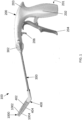
- end effector 400 may include jaws 402, 404, which may be configured to engage respective arms 1002, 1004 of occlusion clip 1000.
- One or both jaws 402, 404 and respective arms 1002, 1004 may be movable from a closed configuration in which jaws 402, 404 and arms 1002, 1004 are generally parallel ( FIG. 1 ) to an open configuration in which one jaw 402 and its associated arm 1002 is nonparallel relative to the other jaw 404 and its associated arm 1004 ( FIG. 2 ).
- activation lever 204 may shift clip applier 100 to the closed configuration ( FIG. 1 ).
- activation lever 204 may be biased away from grip 202, which may place clip applier 100 in the closed configuration ( FIG. 1 ) when external forces, such as from hand grasping of lever 204 and grip 202, are removed from activation lever 204.
- Portions of handle 200 may be constructed of one or more shells 201, 203.
- clip applier 100 may be returned to the open configuration by operating activation lever 204 ( FIGS. 2 and 3 ), repositioned, and returned to the closed configuration by operating activation lever 204 ( FIGS. 1 and 4 ).
- Deployment trigger 206 FIGS. 1 and 2 ) may be operated to deploy occlusion clip 1000, which may release occlusion clip 1000 from end effector 400.
- Clip applier 100 may be moved to withdraw end effector 400 from the anatomical structure 1100, leaving occlusion clip 1000 on occlusion site 1102 of the anatomical structure 1100 ( FIG. 5 ).
- Occlusion clip 1000 may remain as a permanent implant on anatomical structure 1100.
- anatomical structure 1100 may be occluded by clip 1000 without being punctured.
- an occlusion device applicator that may be both held and operated by one hand.
- a surgeon's left hand may be used to support the patient's heart while the surgeon's right hand may be used to hold, position, and/or actuate the occlusion device applicator.
- Some example clip appliers 100 may be configured to permit one-handed operation. Some example clip appliers 100 may be held in one hand, shifted between the open and closed configurations by the holding hand, and/or actuated to deploy occlusion clip 1000 by the holding hand. For example, some clip appliers 100 according to at least some aspects of the present disclosure may be configured for operation of activation lever 204 by one or more fingers of the holding hand. Some example clip appliers 100 according to at least some aspects of the present disclosure may be configured for operation of deployment trigger 206 by one finger, such as the holding hand's index finger.
- track follower 224 may be slidably disposed along a track 226 within handle 200.
- Track 226 may be formed by a first sidewall 228 spaced apart from a second sidewall 230 to slidably receive track follower 224 therebetween.
- first sidewall 228 and/or second sidewall 230 may be formed as part of handle 200 shell 201.
- First sidewall 228 and second sidewall 230 may define track 226 in a nonlinear shape, such as a generally curved, arcuate shape.
- Such movement may pull activation cable 210 generally proximally (e.g., generally away from end effector 400) through shaft 300.
- Such proximal movement of activation cable 210 may cause jaws 402, 404 of end effector 400 to move from the closed configuration ( FIG. 1 ) to the open configuration ( FIG. 2 ).
- Reducing and/or removing the user-applied proximal force applied to activation handle 204 may allow activation handle 204, track follower 224, and activation cable 210 to return to the closed configuration, such as by the action of torsion spring 215 and/or a closed-biased occlusion clip 1000.
- some occlusion device applicators may utilize a mechanical lock and/or a sustained user-applied force to hold an occlusion device (e.g., an occlusion clip) open while positioning the occlusion device on an anatomical structure, such as a LAA.
- an occlusion device e.g., an occlusion clip
- an anatomical structure such as a LAA.
- the present disclosure contemplates that while a mechanical lock may effectively hold the occlusion device open during positioning, such a mechanism may require a cumbersome unlocking action (e.g., disengaging an inconveniently located lock) to permit closure and/or deployment of the occlusion device.
- a cumbersome unlocking action e.g., disengaging an inconveniently located lock
- the length of linkage 212 between rivet 216 and track follower 224, the length of activation lever 204 between activation lever pivot journal 236 and rivet 216, and/or the location and/or shape of track 226 between first location 232 and second location 234 may affect the force that must be applied by a user over the travel of activation lever 204.
- the curvature of track 226 may be limited to cause a generally straighter motion of track follower 224 in portions of travel of activation lever 204 where forces are higher.
- varying the configuration of these various components may vary the force and distance output of the mechanism as activation lever 204 travels between the open configuration and closed configuration.
- Some example embodiments according to at least some aspects of the present disclosure may be configured to require less user-applied force on activation lever 204 near the end of its travel, such as when clip applier is near and/or in the open configuration.
- the pivot point of activation lever 204 activation lever pivot journal 236)
- the direction of activation cable 210 generally between fastener 220 and activation lever pivot journal 236, and track follower 224 may be nearly aligned as activation lever 204 approaches the open configuration, which may increase the mechanical advantage and/or reduce the required force on activation lever 204.
- a clip applier 100 may be configured to utilize a user-applied hold-open force to maintain the open configuration ( FIG. 2 ) that is less than the force required to shift to the open configuration ( FIG. 2 ) from the closed configuration ( FIG. 1 ).
- Some example clip appliers 100 may require application of a generally constant force to activation lever 204 to shift from the open configuration ( FIG. 1 ) toward the closed configuration ( FIG. 2 ) for a substantial portion (e.g., for about 85%) of the length of travel of activation lever 204. Then, for the travel remaining (e.g., about 15%), the force required to continue to the open configuration ( FIG. 2 ), and/or the force required to hold activation lever 204 in the open configuration ( FIG. 2 ), may be less than about half of the force required to begin the shift from closed configuration ( FIG. 1 ) to the open configuration ( FIG. 2 ).
- activation lever 204 may reach a hard stop when clip applier 100 is in the fully open configuration ( FIG. 2 ), which may indicate to the user that clip applier 100 is in the open configuration ( FIG. 2 ) and/or that no additional force or travel may be required. For example, as shown in FIGS. 2 and 7 , a proximal surface of activation lever 204 may contact a distal surface of grip 202.
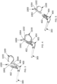
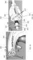
- jaw 402 may be pivotably mounted to a pivot pin 406, and jaw 404 may be pivotably mounted to a pivot pin 408.
- Pivot pins 406, 408 may be affixed to end effector 400 housing 410.
- End effector 400 housing 410 may include two mirror-image portions, one of which is not shown in FIG. 9 for clarity.
- Activation cable 210 may extend distally from handle 200 ( FIGS. 6 and 7 ), through shaft 300, and to a double-tackle pulley mechanism operatively disposed on the proximal portions 412, 414 of jaws 402, 404, respectively.
- Proximal movement of activation cable 210 may cause the length of the activation cable 210 extending between pulleys 416, 418 to decrease, thereby causing proximal ends 412, 414 of jaws 402, 404 to move toward one another.
- This movement of proximal ends 412, 414 of jaws 402, 404 toward one another may coincide with distal ends 420, 422, respectively, of jaws 402, 404 pivoting away from one another about to effectively open jaws 402, 404 and correspondingly opening occlusion clip 1000.
- Distal movement of activation cable 210 may cause the length of the activation cable 210 extending between pulleys 416, 418 to increase (such as by action of torsion spring 215 ( FIG. 8 ) and/or a closed-biased occlusion clip 1000), thereby allowing proximal ends 412, 414 of jaws 402, 404 to move away from one another.
- This movement of proximal ends 412, 414 of jaws 402, 404 apart may coincide with distal ends 420, 422, respectively, of jaws 402, 404 pivoting towards one another about to effectively close jaws 402, 404 and correspondingly closing occlusion clip 1000.
- arm 1004 of occlusion clip 1000 may be attached to jaw 404, such as by sutures 426, 428, which may be disposed proximally with respect to the center of the length of arm 1004 to cause the distal tips of occlusion clip 1000 close first when clip applier 100 ( FIGS. 1 and 2 ) is shifted from the open configuration ( FIG. 2 ) to the closed configuration ( FIG. 1 ).
- jaw opening mechanisms as known in the art, such as cams, gears, and/or linkages, in connection with example embodiments according to at least some aspects of the present disclosure. It is within the scope of the present disclosure utilize jaw opening mechanisms described in U.S. Patent Application Publication No. 2017/0014135, published January 19, 2017 , which is incorporated by reference.
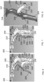
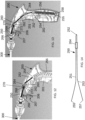
- FIGS. 11-13 are interior perspective views of an example handle 200 showing occlusion clip release components in before deployment, during deployment, and after deployment configurations, respectively, all according to at least some aspects of the present disclosure.
- Deployment trigger 206 may be actuated by a user pressing generally proximally on a trigger face 207.
- Deployment trigger 206 may be operatively coupled to jaws 402, 404 of end effector 400 ( FIGS. 1 and 2 ) by a deployment cable 250, which may extend from handle 200 to end effector 400 through a hollow channel extending through shaft 300.
- a proximal end 252 of deployment cable 250 may be coupled to a first end 254 of an elastic member, such as an extension spring 256.
- a second end 255 of extension spring 256 may be affixed to the interior of handle 200, such as at a boss 258 formed in shell 201.
- Deployment cable 250 may extend from first end 254 of extension spring 256, through a slot 260 in an anchoring plate 262, and to a cable stop, such as a crimp sleeve 264.
- Anchoring plate 262 may be fixedly mounted to shells 201, 203 by extending into anchoring plate slots 213, 215, respectively ( FIGS. 36 and 37 ).
- Slot 260 in anchoring plate 262 may be wider than deployment cable 250 and narrower than crimp sleeve 264, thereby allowing deployment cable 250 to pass through slot 260 while preventing crimp sleeve 264 from passing through slot 260.
- Crimp sleeve 264 may be fixedly attached to deployment cable 250, which may form a loop at proximal end 252 of deployment cable 250.
- Deployment cable 250 may extend distally from the crimp sleeve 264 through shaft 300 to end effector 400 ( FIGS. 1 and 2 ).
- extension spring 256 may be in a relaxed configuration and/or deployment cable 250 may be retracted proximally to a position in which crimp sleeve 264 has cleared anchoring plate 262.
- Deployment cable 250 may extend through slot 260 in anchoring plate 262 and/or through slot 268 in deployment trigger 206.
- deployment cable 250 may be retracted by the force of extension spring 256 about 5 cm (about 2 inches). Compare the position of crimp sleeve 264 in FIG. 11 and FIG. 13 , for example.
- deployment trigger 206, anchoring plate 262, and related components may be configured to reduce the likelihood of unintentional actuation, such as due to handling of the device.
- deployment trigger 206 may be located on handle 200 where it may be unlikely to be inadvertently actuated, deployment trigger 206 may be protected, such as by a trigger guard (see, e.g., FIG. 26 ), actuation of deployment trigger 206 may require removal or disabling a safety device (see, e.g., FIGS. 34 and 35 ), and/or the force and/or travel required actuate deployment trigger 206 may reduce the likelihood of unintentional actuation.
- a trigger guard see, e.g., FIG. 26
- actuation of deployment trigger 206 may require removal or disabling a safety device (see, e.g., FIGS. 34 and 35 )
- the force and/or travel required actuate deployment trigger 206 may reduce the likelihood of unintentional actuation.
- the amount of tensile force exerted on deployment cable 250 by spring 256 and/or the angle at which the proximal end of crimp sleeve 264 contacts the distal face of anchoring plate 262 may affect the force that must be applied to trigger face 207 to shift deployment trigger 206 to cause crimp sleeve 264 to clear anchoring plate 262.
- the depth of slot 260 in anchoring plate 262 and/or the angle of pull of deployment cable 250 on the proximal side of anchoring plate 262 may affect the distance that slot 268 of deployment trigger 206 must move to cause crimp sleeve 264 to clear anchoring plate 262.
- Some example embodiments according to at least some aspects of the present disclosure may provide tactile and/or audible indications that deployment trigger 206 and related components have been successfully actuated, thus releasing occlusion clip 1000 from end effector 400.
- inertia from extension spring 256 hitting its stop location may provide tactile and/or audible indications that the deployment mechanism has been actuated.
- Some example embodiments may include a noise-producing component, such as a bell.
- FIG. 14 is an elevation view of an example deployment cable 250 according to at least some aspects of the present disclosure.
- Deployment cable 250 may include a first strand 251 and/or a second strand 253 extending distally from crimp sleeve 264.
- deployment cable 250 may be constructed from a length of cable bent near its center to form a loop at proximal end 252 for attachment to extension spring 256 ( FIGS. 11-13 ).
- First strand 251 may extend through shaft 300 to jaw 402, ending at a first strand end 255.
- Second strand 253 may extend through shaft 300 to jaw 404, ending at a second strand end 257.
- deployment cables 250 including first strand 251 and second strand 253, pulling on proximal end 252 may cause first strand end 255 and second strand end 257 to move proximally generally in parallel.
- first strand 251 and second strand 253 of deployment cable 250 may extend distally from handle 200, through shaft 300, to end effector 400.
- the following description focuses on jaw 404 and second strand 253; however, jaw 402 and first strand 251 may be configured and operate in a substantially similar manner.
- deployment cable 250 is repositioned proximally (such as by actuating deployment trigger 206 to allow extension spring 256 to withdraw cable 250 proximally) and second strand 253 discontinues engagement with the suture loops 426, 428 that were previously concurrently attached to occlusion clip 1000 and jaw 404.
- suture loops 426, 428 may be pulled through respective openings 430, 432 toward arm 1004 to free arm 1004 of occlusion clip 1000 from jaw 404.
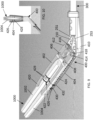
- FIG. 15 is a detailed perspective view of a distal portion of an example handle 200, according to at least some aspects of the present disclosure.
- FIG. 16 is a detailed perspective view of a proximal portion of an example shaft 300, according to at least some aspects of the present disclosure.
- FIG. 17 is a detailed internal perspective view of an example shaft 300 and handle 200 in a locked configuration, according to at least some aspects of the present disclosure.
- FIG. 18 is a detailed internal perspective view of an example shaft 300 and handle 200 in an unlocked configuration, according to at least some aspects of the present disclosure.
- FIG. 19 is an internal perspective view of a distal portion of an example handle with an example shaft in a rotated configuration, according to at least some aspects of the present disclosure.
- spring 316 may be at least partially extended and locking boss 312 of shaft rotation knob 302 may be at least partially engaged proximally within locking recess 276 of handle 200. Accordingly, rotation of shaft 300 relative to handle 200 may be prevented by the engagement of outwardly facing locking faces 314 of locking boss 312 with respective inwardly facing locking faces 278 of locking recess 276.
- proximal face 310 of shaft rotation knob 302 may contact distal face 274 of handle 200 when shaft rotation knob 302 is in the locked configuration.
- an example shaft rotation knob 302 may include a rotation limiting feature, such as a stop 324.
- Stop 324 may include one or more stop faces 326, 328, which may be disposed to engage a rotation limiting feature, such as generally longitudinally extending bar 282 disposed on handle 200 (e.g., on shell 201), when shaft rotation knob 302 is rotated a predefined maximum desired amount.
- stop face 326 may engage bar 282 and prevent further rotation when shaft rotation knob 302 is rotated about 90 degrees clockwise when looking distally.
- Stop face 328 may engage bar 282 and prevent further rotation when shaft rotation knob 302 is rotated about 90 degrees counterclockwise when looking distally.
- FIG. 21 is a detailed internal perspective view of alternative example occlusion clip release components in a during deployment configuration.
- crimp sleeve 264 on deployment cable 250 may be longitudinally slidably disposed within, but restrained laterally by, a fixed slot 284, which may be fixedly disposed inside handle 200A.
- a movable anchoring plate 286 including a slot 288 may be arranged to prevent proximal movement of crimp sleeve 264 in a before deployment configuration.
- crimp sleeve 264 may at least partially abut anchoring plate 286.
- a user-activated deployment trigger, such as deployment button 290 may be pivotably disposed on handle 200A and may be operatively coupled to anchoring plate 286.
- FIGS. 22-24 are perspective views, according to at least some aspects of the present disclosure, of alternative example locations and configurations for user-activated deployment triggers, such as deployment buttons 290A, 290B, 290C, which may operate substantially similarly to user-activated deployment button 290 described in connection with FIG. 21 or deployment trigger 206 ( FIGS. 11-13 ).
- deployment buttons 290A, 290B, 290C which may operate substantially similarly to user-activated deployment button 290 described in connection with FIG. 21 or deployment trigger 206 ( FIGS. 11-13 ).
- FIG. 25 is a perspective view of an alternative example clip applier 600 including a thumbwheel deployment cable retractor 602, according to at least some aspects of the present disclosure.
- a thumbwheel retractor mechanism may be used to retract deployment cable 250 in place of a mechanism including deployment trigger 206, anchoring plate 262, and extension spring 256 and related components.
- rotation of a thumbwheel 602 (such as by a user's thumb) may retract deployment cable 250.
- a thumbwheel mechanism may facilitate one-handed operation and/or may allow for improved control of the clip applier 600.
- FIG. 26 is a perspective view of an alternative example clip applier 604 including a lever actuated deployment cable retractor, according to at least some aspects of the present disclosure.
- clip applier 604 may include a deployment lever 606, which may be placed in an ergonomically appropriate location and/or which may be pivoted by a user to retract deployment cable 250.
- a pulley system may be used to increase the stroke length required to retract the cable past the suture loops.
- Some example embodiments including a lever actuated deployment cable retractor may facilitate one-handed operation and/or improved control of the clip applier 604.
- deployment lever 606 may be disposed in a location that may be protected from inadvertent operation by a trigger guard 608.
- a lever actuated deployment cable retractor may be used to retract deployment cable 250 in place of a mechanism including deployment trigger 206, anchoring plate 262, and extension spring 256 and related components.
- FIG. 27 is a perspective view of an alternative example clip applier 610 including a pull tab 612 deployment cable retractor, according to at least some aspects of the present disclosure.
- pull tab 612 may include a hole that can readily be manipulated, such as with one finger. Pull tab 612 may be actuated using a twisting motion to free (e.g., unlock) pull tab 612. For example, pull tab 612 may be rotated clockwise or counterclockwise by a predetermined amount, which may be about 45 to about 90 degrees. Then, pull tab 612 may be pulled proximally to withdraw deployment cable 250 and release the occlusion device. In some example embodiments, one or more ears of pull tab 612 may lock into the handle when pull tab 612 is in a locked configuration.
- FIG. 28 is a side elevation view of an alternative example clip applier 614 including a torsion spring cable retractor, according to at least some aspects of the present disclosure.
- Some example embodiments may operate generally similar to a retractable tape measure.
- a torsion spring 616 may be operatively coupled to a spool 618, which may receive deployment cable 250.
- Clip applier 614 may be provided with torsion spring 616 pre-torsioned so that spool 618 applies proximal tension on deployment cable 250.
- a retainer 620 may selectively prevent proximal withdrawal (e.g., retraction) of deployment cable 250 until retainer 620 is disengaged by a user, such as by pressing a deployment button 622.
- FIGS. 29-31 are side elevation views of example methods for attaching strands 251, 253 of deployment cable 250 to torsion spring 616, according to at least some aspects of the present disclosure.
- FIG. 29 illustrates attachment using a crimp plate 634, which may couple strands 251, 253 of deployment cable 250 to torsion spring 616.
- FIG. 30 illustrates attachment using solder 636, which may couple strands 251, 253 of deployment cable 250 to torsion spring 616.
- FIG. 31 illustrates attachment using a fastener 638 (such as a rivet or similar fastener), which may couple strands 251, 253 of deployment cable 250 to torsion spring 616.
- a fastener 638 such as a rivet or similar fastener
- safety tabs 624, 630 may be easily identifiable, such as by color or other markings.
- a safety tab 624, 630 may block operation of the clip deployment mechanism (in addition to blocking operation of the user-activated trigger or button), which may inhibit inadvertent actuation of the deployment mechanism due to inertia, such as if the clip applier is dropped.
- U.S. Patent No. 9,901,352 titled “Occlusion Clip” and incorporated herein by reference, describes example occlusion clips that may be used with at least some embodiments according to the present disclosure. Some example embodiments according to at least some aspects of the present disclosure may be configured for use with clips that are open-ended, closed-biased, and/or close tip-first. Some example embodiments may be used with closed-ended occlusion clips.
- Statement 6 The medical instrument of statement 1, wherein the activation lever is operatively coupled to the first jaw by an activation cable extending through the shaft.
- Statement 42 The medical instrument of statement 33, wherein the shaft comprises at least one of aluminum, copper, stainless steel, and polycarbonate.
- Statement 43 The medical instrument of statement 33, wherein the shaft is deformable up to an angle of at least about 45 degrees.
- Statement 49 The method of statement 47, further comprising, while positioning the occlusion clip adjacent to the occlusion site, maintaining the clip applier in the open configuration by continuing to apply the external force on the activation lever, the force required for maintaining the clip applier in the open configuration being less than the external force required for moving the activation lever from the closed activation lever configuration to the open activation lever configuration.
- Statement 65 The method of statement 60, further comprising, before positioning the occlusion clip adjacent to the occlusion site, plastically deforming the shaft.
- Statement 66 The method of statement 60, further comprising
Landscapes
- Health & Medical Sciences (AREA)
- Surgery (AREA)
- Life Sciences & Earth Sciences (AREA)
- Heart & Thoracic Surgery (AREA)
- Nuclear Medicine, Radiotherapy & Molecular Imaging (AREA)
- Vascular Medicine (AREA)
- Engineering & Computer Science (AREA)
- Biomedical Technology (AREA)
- Reproductive Health (AREA)
- Medical Informatics (AREA)
- Molecular Biology (AREA)
- Animal Behavior & Ethology (AREA)
- General Health & Medical Sciences (AREA)
- Public Health (AREA)
- Veterinary Medicine (AREA)
- Surgical Instruments (AREA)
Applications Claiming Priority (4)
| Application Number | Priority Date | Filing Date | Title |
|---|---|---|---|
| US201762586020P | 2017-11-14 | 2017-11-14 | |
| US201762611247P | 2017-12-28 | 2017-12-28 | |
| PCT/US2018/060955 WO2019099466A1 (fr) | 2017-11-14 | 2018-11-14 | Applicateur d'agrafes |
| EP18879321.0A EP3709901B1 (fr) | 2017-11-14 | 2018-11-14 | Applicateur d'agrafes |
Related Parent Applications (1)
| Application Number | Title | Priority Date | Filing Date |
|---|---|---|---|
| EP18879321.0A Division EP3709901B1 (fr) | 2017-11-14 | 2018-11-14 | Applicateur d'agrafes |
Publications (2)
| Publication Number | Publication Date |
|---|---|
| EP4393419A2 true EP4393419A2 (fr) | 2024-07-03 |
| EP4393419A3 EP4393419A3 (fr) | 2024-11-13 |
Family
ID=66431117
Family Applications (2)
| Application Number | Title | Priority Date | Filing Date |
|---|---|---|---|
| EP18879321.0A Active EP3709901B1 (fr) | 2017-11-14 | 2018-11-14 | Applicateur d'agrafes |
| EP24175773.1A Pending EP4393419A3 (fr) | 2017-11-14 | 2018-11-14 | Applicateur d'agrafes |
Family Applications Before (1)
| Application Number | Title | Priority Date | Filing Date |
|---|---|---|---|
| EP18879321.0A Active EP3709901B1 (fr) | 2017-11-14 | 2018-11-14 | Applicateur d'agrafes |
Country Status (5)
| Country | Link |
|---|---|
| US (4) | US11439406B2 (fr) |
| EP (2) | EP3709901B1 (fr) |
| JP (2) | JP7286641B2 (fr) |
| CN (2) | CN111712201B (fr) |
| WO (1) | WO2019099466A1 (fr) |
Families Citing this family (18)
| Publication number | Priority date | Publication date | Assignee | Title |
|---|---|---|---|---|
| EP3193790A4 (fr) | 2014-09-19 | 2018-10-03 | Flow Medtech, Inc. | Système de placement de dispositif d'occlusion d'appendice auriculaire gauche |
| US12239292B2 (en) | 2019-01-10 | 2025-03-04 | Atricure, Inc. | Clip application system and method |
| US12605176B2 (en) | 2019-01-23 | 2026-04-21 | Atricure, Inc. | Left atrial appendage manipulation and traction |
| CN112336403B (zh) * | 2019-08-06 | 2024-09-24 | 北京领健医疗科技有限公司 | 一种闭合器输送系统 |
| CN110522489A (zh) * | 2019-09-29 | 2019-12-03 | 山东威瑞外科医用制品有限公司 | 一种施夹钳器械 |
| US11273025B2 (en) | 2019-11-22 | 2022-03-15 | Pro Verum Limited | Expandable implant delivery device |
| US11602621B2 (en) | 2019-11-22 | 2023-03-14 | ProVerum Limited | Device for controllably deploying expandable implants |
| EP4061200B1 (fr) | 2019-11-22 | 2024-11-06 | Proverum Limited | Dispositif et procédé pour déployer des implants extensibles |
| US12213681B2 (en) | 2020-05-06 | 2025-02-04 | Atricure, Inc. | End effector positioning mechanism |
| US12426886B2 (en) | 2020-11-23 | 2025-09-30 | Eric William Schneeberger | Atrial appendage excluder |
| WO2022175835A1 (fr) * | 2021-02-17 | 2022-08-25 | Auris Health, Inc. | Commande de rouleau d'instrument |
| AU2022341186A1 (en) | 2021-09-13 | 2024-03-21 | Atricure, Inc. | Exclusion devices and related methods |
| CN121358439A (zh) | 2023-04-27 | 2026-01-16 | 普罗凡仑姆有限公司 | 用于部署可扩张植入物的器械和方法 |
| GB2629407A (en) * | 2023-04-27 | 2024-10-30 | Proverum Ltd | Device and method for deploying expandable implants |
| EP4704728A1 (fr) * | 2023-05-05 | 2026-03-11 | Edwards Lifesciences Corporation | Système pour pince d'appendice auriculaire gauche |
| US12446892B2 (en) | 2023-09-08 | 2025-10-21 | Atricure, Inc. | Dual side spring V-clip for surgical treatment of left atrial appendage |
| WO2025224620A1 (fr) * | 2024-04-25 | 2025-10-30 | Boston Scientific Medical Device Limited | Dispositifs médicaux et systèmes et procédés d'utilisation associés |
| CN118303953B (zh) * | 2024-06-11 | 2024-08-16 | 吉林省金博弘智能科技有限责任公司 | 一种手持手枪形多角度可弯曲手术器械 |
Citations (3)
| Publication number | Priority date | Publication date | Assignee | Title |
|---|---|---|---|---|
| US20170014135A1 (en) | 2015-07-14 | 2017-01-19 | Keith Edward Martin | Surgical tool |
| US20180036007A1 (en) | 2016-08-08 | 2018-02-08 | Atricure, Inc. | Robotic assisted clip applier |
| US9901352B2 (en) | 2014-12-12 | 2018-02-27 | Atricure, Inc. | Occlusion clip |
Family Cites Families (23)
| Publication number | Priority date | Publication date | Assignee | Title |
|---|---|---|---|---|
| US5287949A (en) * | 1988-03-04 | 1994-02-22 | Nhk Spring Co., Ltd. | Shaft locking device |
| US5240163A (en) | 1991-10-30 | 1993-08-31 | American Cyanamid Company | Linear surgical stapling instrument |
| US5582615A (en) | 1995-10-30 | 1996-12-10 | Pilling Weck, Incorporated | Handle for surgical clip applicator systems |
| US5776155A (en) * | 1996-12-23 | 1998-07-07 | Ethicon Endo-Surgery, Inc. | Methods and devices for attaching and detaching transmission components |
| US20010034536A1 (en) | 1997-09-25 | 2001-10-25 | Looper Anthony M. | Surgical device with malleable shaft |
| US6139563A (en) * | 1997-09-25 | 2000-10-31 | Allegiance Corporation | Surgical device with malleable shaft |
| US6350269B1 (en) | 1999-03-01 | 2002-02-26 | Apollo Camera, L.L.C. | Ligation clip and clip applier |
| US6270476B1 (en) * | 1999-04-23 | 2001-08-07 | Cryocath Technologies, Inc. | Catheter |
| EP1296604B1 (fr) * | 2000-04-27 | 2007-01-10 | Cryocath Technologies inc. | Catheter |
| US8172870B2 (en) | 2003-06-09 | 2012-05-08 | Microline Surgical, Inc. | Ligation clip applier |
| US7083075B2 (en) * | 2003-09-29 | 2006-08-01 | Ethicon Endo-Surgery, Inc. | Multi-stroke mechanism with automatic end of stroke retraction |
| AU2006264404B2 (en) * | 2005-07-06 | 2012-08-02 | I.B.I Israel Biomedical Innovations Ltd. | Surgical fasteners and fastening devices |
| US8795325B2 (en) | 2006-10-05 | 2014-08-05 | Covidien Lp | Handle assembly for articulated endoscopic instruments |
| WO2010011661A1 (fr) * | 2008-07-21 | 2010-01-28 | Atricure, Inc. | Appareil et procédés d'occlusion d'une structure anatomique |
| US8142451B2 (en) * | 2009-01-26 | 2012-03-27 | Microline Surgical, Inc. | Actuator and detachable connector of flexible clip applier |
| US9265486B2 (en) | 2011-08-15 | 2016-02-23 | Atricure, Inc. | Surgical device |
| US9282973B2 (en) | 2012-01-20 | 2016-03-15 | Atricure, Inc. | Clip deployment tool and associated methods |
| US8968311B2 (en) | 2012-05-01 | 2015-03-03 | Covidien Lp | Surgical instrument with stamped double-flag jaws and actuation mechanism |
| US20160038341A1 (en) | 2014-08-08 | 2016-02-11 | Acclarent, Inc. | Tympanostomy tube delivery device with elastomeric brake |
| US10166065B2 (en) * | 2014-12-03 | 2019-01-01 | Ethicon Llc | Devices and methods for clamping and cutting tissue |
| US10159491B2 (en) * | 2015-03-10 | 2018-12-25 | Covidien Lp | Endoscopic reposable surgical clip applier |
| US10631874B2 (en) * | 2015-07-15 | 2020-04-28 | Atricure, Inc. | Surgical tool |
| CA3001755A1 (fr) * | 2015-10-20 | 2017-04-27 | Lumendi Ltd. | Instruments medicaux permettant d'effectuer des interventions a effraction minimale |
-
2018
- 2018-11-14 CN CN201880086341.1A patent/CN111712201B/zh active Active
- 2018-11-14 JP JP2020526421A patent/JP7286641B2/ja active Active
- 2018-11-14 CN CN202410318588.9A patent/CN118203385A/zh active Pending
- 2018-11-14 EP EP18879321.0A patent/EP3709901B1/fr active Active
- 2018-11-14 WO PCT/US2018/060955 patent/WO2019099466A1/fr not_active Ceased
- 2018-11-14 EP EP24175773.1A patent/EP4393419A3/fr active Pending
- 2018-11-14 US US16/190,417 patent/US11439406B2/en active Active
-
2022
- 2022-07-28 US US17/875,582 patent/US12446893B2/en active Active
-
2023
- 2023-05-23 JP JP2023084809A patent/JP7817210B2/ja active Active
-
2025
- 2025-09-25 US US19/340,447 patent/US20260020862A1/en active Pending
- 2025-09-25 US US19/340,306 patent/US20260020861A1/en active Pending
Patent Citations (3)
| Publication number | Priority date | Publication date | Assignee | Title |
|---|---|---|---|---|
| US9901352B2 (en) | 2014-12-12 | 2018-02-27 | Atricure, Inc. | Occlusion clip |
| US20170014135A1 (en) | 2015-07-14 | 2017-01-19 | Keith Edward Martin | Surgical tool |
| US20180036007A1 (en) | 2016-08-08 | 2018-02-08 | Atricure, Inc. | Robotic assisted clip applier |
Also Published As
| Publication number | Publication date |
|---|---|
| CN111712201A (zh) | 2020-09-25 |
| US20220361886A1 (en) | 2022-11-17 |
| JP2021502855A (ja) | 2021-02-04 |
| JP7286641B2 (ja) | 2023-06-05 |
| US20260020862A1 (en) | 2026-01-22 |
| EP3709901B1 (fr) | 2024-06-12 |
| US20190142428A1 (en) | 2019-05-16 |
| US11439406B2 (en) | 2022-09-13 |
| WO2019099466A1 (fr) | 2019-05-23 |
| US20260020861A1 (en) | 2026-01-22 |
| JP7817210B2 (ja) | 2026-02-18 |
| EP3709901A1 (fr) | 2020-09-23 |
| CN111712201B (zh) | 2024-04-19 |
| US12446893B2 (en) | 2025-10-21 |
| EP3709901A4 (fr) | 2021-10-27 |
| JP2023099707A (ja) | 2023-07-13 |
| CN118203385A (zh) | 2024-06-18 |
| EP4393419A3 (fr) | 2024-11-13 |
Similar Documents
| Publication | Publication Date | Title |
|---|---|---|
| US12446893B2 (en) | Clip applier | |
| US10166038B2 (en) | Minimally invasive surgical assembly and methods | |
| JP7758774B2 (ja) | 腹腔鏡下縫合システム | |
| US9486238B2 (en) | Minimally invasive surgical clamps, assemblies and methods | |
| EP2967613B1 (fr) | Poignées de dispositif médical | |
| JP6067512B2 (ja) | 組織をクリップ留めするデバイス | |
| US9510824B2 (en) | Low profile medical device and related methods of use | |
| US9168050B1 (en) | End effector construction | |
| US9936943B1 (en) | Suture passing surgical device with atraumatic grasper preventing accidental perforations | |
| CN106456202A (zh) | 手术抓钳 | |
| CN103619270A (zh) | 组织牵开器组件 | |
| JP2014133130A (ja) | 外科手術クリップアプライヤ | |
| US11642189B2 (en) | Surgical instrument with fastener preload lock-out | |
| CN101478923B (zh) | 最小侵入性手术组件 | |
| JP7369624B2 (ja) | 縫合糸配置装置および方法 | |
| EP3468488A1 (fr) | Dispositif laparoscopique | |
| WO2017212040A1 (fr) | Dispositif laparoscopique | |
| CN112243362B (zh) | 缝合线穿引器装置及方法 |
Legal Events
| Date | Code | Title | Description |
|---|---|---|---|
| PUAI | Public reference made under article 153(3) epc to a published international application that has entered the european phase |
Free format text: ORIGINAL CODE: 0009012 |
|
| STAA | Information on the status of an ep patent application or granted ep patent |
Free format text: STATUS: THE APPLICATION HAS BEEN PUBLISHED |
|
| REG | Reference to a national code |
Ref country code: DE Ref legal event code: R079 Free format text: PREVIOUS MAIN CLASS: A61B0017290000 Ipc: A61B0017128000 |
|
| AC | Divisional application: reference to earlier application |
Ref document number: 3709901 Country of ref document: EP Kind code of ref document: P |
|
| AK | Designated contracting states |
Kind code of ref document: A2 Designated state(s): AL AT BE BG CH CY CZ DE DK EE ES FI FR GB GR HR HU IE IS IT LI LT LU LV MC MK MT NL NO PL PT RO RS SE SI SK SM TR |
|
| RIC1 | Information provided on ipc code assigned before grant |
Ipc: A61B 17/29 20060101ALN20240620BHEP Ipc: A61B 17/00 20060101ALN20240620BHEP Ipc: A61B 17/128 20060101AFI20240620BHEP |
|
| PUAL | Search report despatched |
Free format text: ORIGINAL CODE: 0009013 |
|
| AK | Designated contracting states |
Kind code of ref document: A3 Designated state(s): AL AT BE BG CH CY CZ DE DK EE ES FI FR GB GR HR HU IE IS IT LI LT LU LV MC MK MT NL NO PL PT RO RS SE SI SK SM TR |
|
| RIC1 | Information provided on ipc code assigned before grant |
Ipc: A61B 17/29 20060101ALN20241004BHEP Ipc: A61B 17/00 20060101ALN20241004BHEP Ipc: A61B 17/128 20060101AFI20241004BHEP |
|
| STAA | Information on the status of an ep patent application or granted ep patent |
Free format text: STATUS: REQUEST FOR EXAMINATION WAS MADE |
|
| 17P | Request for examination filed |
Effective date: 20250505 |
|
| STAA | Information on the status of an ep patent application or granted ep patent |
Free format text: STATUS: EXAMINATION IS IN PROGRESS |
|
| 17Q | First examination report despatched |
Effective date: 20260209 |