EP4393464A2 - Soin ou soin. chariot d'organisation - Google Patents
Soin ou soin. chariot d'organisation Download PDFInfo
- Publication number
- EP4393464A2 EP4393464A2 EP24176779.7A EP24176779A EP4393464A2 EP 4393464 A2 EP4393464 A2 EP 4393464A2 EP 24176779 A EP24176779 A EP 24176779A EP 4393464 A2 EP4393464 A2 EP 4393464A2
- Authority
- EP
- European Patent Office
- Prior art keywords
- corner post
- care
- adapter
- trolley
- connecting element
- Prior art date
- Legal status (The legal status is an assumption and is not a legal conclusion. Google has not performed a legal analysis and makes no representation as to the accuracy of the status listed.)
- Pending
Links
- 230000008520 organization Effects 0.000 title claims abstract description 31
- 239000000463 material Substances 0.000 claims description 3
- 239000002184 metal Substances 0.000 claims description 3
- 230000008878 coupling Effects 0.000 claims description 2
- 238000010168 coupling process Methods 0.000 claims description 2
- 238000005859 coupling reaction Methods 0.000 claims description 2
- 230000001066 destructive effect Effects 0.000 claims description 2
- 230000005291 magnetic effect Effects 0.000 claims description 2
- 230000000474 nursing effect Effects 0.000 description 6
- 239000000645 desinfectant Substances 0.000 description 2
- 229940127554 medical product Drugs 0.000 description 2
- 229910000831 Steel Inorganic materials 0.000 description 1
- 238000013016 damping Methods 0.000 description 1
- 238000011161 development Methods 0.000 description 1
- 230000018109 developmental process Effects 0.000 description 1
- 230000009977 dual effect Effects 0.000 description 1
- 230000000694 effects Effects 0.000 description 1
- 230000005294 ferromagnetic effect Effects 0.000 description 1
- 238000000034 method Methods 0.000 description 1
- 230000036316 preload Effects 0.000 description 1
- 239000010959 steel Substances 0.000 description 1
Images


Classifications
-
- A—HUMAN NECESSITIES
- A61—MEDICAL OR VETERINARY SCIENCE; HYGIENE
- A61G—TRANSPORT, PERSONAL CONVEYANCES, OR ACCOMMODATION SPECIALLY ADAPTED FOR PATIENTS OR DISABLED PERSONS; OPERATING TABLES OR CHAIRS; CHAIRS FOR DENTISTRY; FUNERAL DEVICES
- A61G12/00—Accommodation for nursing, e.g. in hospitals, not covered by groups A61G1/00 - A61G11/00, e.g. trolleys for transport of medicaments or food; Prescription lists
- A61G12/001—Trolleys for transport of medicaments, food, linen, nursing supplies
-
- A—HUMAN NECESSITIES
- A47—FURNITURE; DOMESTIC ARTICLES OR APPLIANCES; COFFEE MILLS; SPICE MILLS; SUCTION CLEANERS IN GENERAL
- A47B—TABLES; DESKS; OFFICE FURNITURE; CABINETS; DRAWERS; GENERAL DETAILS OF FURNITURE
- A47B31/00—Service or tea tables, trolleys, or wagons
- A47B2031/006—Medication carts
-
- B—PERFORMING OPERATIONS; TRANSPORTING
- B25—HAND TOOLS; PORTABLE POWER-DRIVEN TOOLS; MANIPULATORS
- B25H—WORKSHOP EQUIPMENT, e.g. FOR MARKING-OUT WORK; STORAGE MEANS FOR WORKSHOPS
- B25H1/00—Work benches; Portable stands or supports for positioning portable tools or work to be operated on thereby
- B25H1/08—Work benches; Portable stands or supports for positioning portable tools or work to be operated on thereby with provision for attachment of work holders
-
- B—PERFORMING OPERATIONS; TRANSPORTING
- B25—HAND TOOLS; PORTABLE POWER-DRIVEN TOOLS; MANIPULATORS
- B25H—WORKSHOP EQUIPMENT, e.g. FOR MARKING-OUT WORK; STORAGE MEANS FOR WORKSHOPS
- B25H1/00—Work benches; Portable stands or supports for positioning portable tools or work to be operated on thereby
- B25H1/10—Work benches; Portable stands or supports for positioning portable tools or work to be operated on thereby with provision for adjusting holders for tool or work
Definitions
- the corner post is not inserted at the side of the trolley, but in the corner profile of the trolley, and all the bracket elements and adapters mounted on the corner post can be pivoted horizontally to the center of the respective trolleys or inwards in order to line up the trolleys next to one another.
- a pre-tension against the corner post is provided on the connecting element of the bracket element and/or the adapter.
- the vertical extension of the connecting element is at least one tenth of the length of the bracket element, preferably at least one fifth, in order to ensure a sufficiently large clamping surface for the bracket element on the corner post.
- the bracket body can be connected to the connecting element, e.g. by snapping it into an undercut or additional steel pins, and can be separated from it if necessary. This means that bracket elements of different lengths can be used on the trolley for different application scenarios if required.
- the adapter also has two holding elements, namely the connecting element and the groove.
- the connecting element and the groove extend perpendicular to each other and are therefore intended for vertical storage on the one hand and horizontal storage on the other.
- the adapter can be mounted on the bracket element or cross bracket as well as on the corner post.
- the connecting element, and therefore also the relevant retaining element of the adapter, which can be used for vertical storage, is essentially U-shaped when viewed from above. This allows the adapter to be clipped onto a vertical corner post.
- the holding element of the adapter for horizontal attachment extends at an approximately right angle to the vertical holding element and has a U-shape in side view, namely a groove that is open at the bottom. This means that the desired care or organizational utensil can be fixed to both a horizontal and vertical part of the trolley using the adapter.
- the bracket element has a further connecting element which is connected to the end of the bracket element remote from the corner post and is connected to a further post which is in particular shorter than the corner post, wherein the further post ends above the trolley body or the worktop.
- the horizontal bracket element can also be referred to as a cross bracket in this embodiment.
- the medical staff can easily grasp the second post to pivot the bracket element or crossbar and thus pivot the crossbar.
- At least two corner posts are provided which extend vertically parallel to one another and can be fixed to the trolley body at least indirectly, and between which and on which at least one bracket element for attaching accessories to the care or organization trolley can be stored.
- the embodiment of the care or organization trolley 100 according to the invention shown has a trolley body 2, a corner profile 4 and a corner post 10.
- the trolley body 2 is in Fig.1 only partially shown schematically.
- the corner profile 4 has a fastening channel 6 which extends vertically and into which the corner post 10 engages and is fixed there.
- This embodiment of the care or organization trolley 100 also has a bracket element 20 and an adapter 30 for holding accessories.
- the bracket element 20 is mounted on the corner post 10 with a connecting element 22 made of plastic.
- the connecting element 22 of the bracket element 20 is optionally detachably connected to a bracket body 24 which extends in the longitudinal direction of the bracket element 20.
- the adapter 30 is mounted on or on the bracket element 20.
- the accessory 1 is attached to the adapter 30 with a fastening element 38 ( Fig.3 ) attached.
- the adapter 30 can be mounted on the bracket element 20 and the bracket element 20 can be mounted on the corner post 10 without tools by clamping it and can be separated from it without tools. This avoids incorrect assembly of the bracket element 20 and the adapter 30 as far as possible and at the same time speeds up the attachment of accessories to the trolley.
- bracket element 20 can be pivoted horizontally around the corner post 10.
- bracket element 20 can be swiveled horizontally inwards. This means that the accessory 1 no longer remains to the side of the trolley 100 during transport, but above the worktop 8, which prevents accidental side impacts.
- bracket element 20 improves the handling of care or organization carts.
- a well-known nursing and organisation cart has a rail system on the side of the cart body for attaching accessories, and it is almost impossible to line up the carts directly next to one another due to the rail system attached to the side with accessories stored on it.
- the corner posts 10 are inserted into the corner profile 4 of the carriage 100, and the bracket element 20 mounted on the corner post 10 can be pivoted horizontally inwards in order to leave the spaces at the sides of the carriage free for the carriage 100 to be lined up one after the other.
- the bracket element 20 can be stored in the longitudinal direction of the corner post 10 at any discrete location on the corner post 10
- the adapter 30 can be stored in the longitudinal direction of the bracket element 20 at any location on the bracket element 20.
- the corner post 10 has on its radially outer side a plurality of grooves 12 for forming the discrete locations, each of which extends horizontally around the corner post 10.
- the connecting element 22 of the bracket element 20 has a Fig.1 not shown projection, which fits into the groove 12 and forms a positive connection of the bracket element 20 with the corner post 10.
- the strength of the mounting of the bracket element 20 on the corner post 10 is significantly increased by this positive connection.
- this positive connection avoids vibrations of the bracket element 10 as far as possible, which vibrates during transport due to the leverage effect on the corner post 10 and possibly also due to its elastic connecting element 22 made of plastic.
- the adapter 30 on the bracket element 20 also contributes to this, which adapter 30 exerts a preload on the bracket element 20.
- the radially inward-facing projection of the bracket element 20 extends between two grooves 12 on the outside of the corner post 10, if necessary, and is not yet precisely engaged in the desired groove 12.
- a gap remains between the outside of the corner post 10 and the inside of the U-shaped connecting element 22.
- the connecting element 22 is then moved slightly upwards or downwards until the projection of the connecting element 22 engages in the desired groove 12.
- the outer diameter of the corner post 10 is, for example, approximately 2 mm larger than the inner diameter of the connecting element 22, a firm locking connection in combination with a stable clamp connection is possible.
- the bracket body 24 is a hollow profile made of light metal. This makes it possible to produce a sufficiently strong bracket with a low weight of the bracket element 22, the load-bearing capacity of which is optimized.
- the bracket body 24 can be easily connected to and separated from the connecting element 22 by plugging it in. This means that bracket elements 20 with different lengths can be used on the carriage 100 for different application scenarios.
- a groove-shaped receiving space 32 of the adapter 30 is provided.
- the receiving space 32 enables the adapter to be plugged onto the bracket element 20, in particular by clamping it.
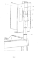
- Fig.2 the connection of the accessory part 1 with the adapter 30 is visible.
- the accessory part 1 is attached to the adapter 30 with two screws 34 via its fastening device 38 ( Fig.3 ) attached.
- the connecting element 22 of the bracket element 20 is clamped to the corner post 10 and is, in plan view, quasi horseshoe-shaped or essentially U-shaped.
- the connecting element has a wrap angle 26 which is in accordance with the Fig.2 In the embodiment shown, the angle of contact is approximately 240°. With such an angle of contact, a sufficiently large clamping surface is achieved. This ensures a release force of at least 10 KN, in particular at least 50 KN.
- the connecting element 22 is made of plastic and in this embodiment is approximately 7 cm high.
- Two side legs 36b of the groove 36 form a cuboid-shaped back element 37 of the adapter 30.
- Two internal threads are provided on the back element 37 for the screw connection with the accessory part 1 to form the fastening device 38.
- the adapter 30 is mounted directly on the corner post 10 by clamping.
- the adapter 30 therefore has a dual function in that it allows clamping directly to the corner post 10 or optionally to the bracket element 20, each for storing the accessory 1 attached to the adapter 30.
- the inner diameter of the connecting element 22 of the adapter 30 is slightly smaller than the outer diameter of the corner post 10.
- the adapter 30 has on its connecting element 22 a Fig.1 visible projection which, like the projection of the connecting element 22 of the bracket element 20, corresponds to the groove 12 of the corner post 10 and forms a positive locking connection of the adapter 30 with the corner post 10.
- the adapter 30 made of plastic can be pivoted around the corner post 10.
- the adapter 30 without the projection can be pivoted about a corner post 10 without grooves 12.
- a further embodiment of the care or organization trolley has a worktop 8 with a corner hole 9.
- the worktop 8 is partially made of plastic and is fixed to the trolley body by clamping it on.
- the corner hole 9 passes vertically through the worktop 8.
- the corner post 10 engages via the corner hole 9 of the worktop 8 into the fastening channel 6 of the corner profile 4.
- the surface area of the worktop 8 is larger than the upper surface of the trolley body which is adjacent to the corner profile 4.
- two further bracket elements 21 and 23 are mounted on the corner post 10.
- the bracket elements or cross brackets 20 and 21 each have a further connecting element 25, which is connected to the end of the cross brackets 20 and 21 that is remote from the corner post 10 and is connected to a further post 11 that is shorter than the corner post 10.
- the further connecting elements 25 are the same injection-molded parts as the connecting elements 22.
- the further post 11 ends above the trolley body or the worktop 8.
- the medical staff can easily grasp the second post 11, which ends above the trolley body or the worktop 8, and then exert a force inwards or outwards.
- the cross brackets 21 and 20 each have a projection for positive connection with the grooves 12 of the corner post 10, which are arranged adjacent to one another.
- Fig.6 another preferred embodiment of the trolley 100 is shown, which has two corner posts 10.
- the two corner posts 10 extend vertically parallel to one another and are fixed to the corner profiles 4 of the trolley 100 via the worktop 8. Between the two corner posts 10 and on them are mounted two crossbars 20 and 21, which lie parallel one above the other, for attaching accessories to the trolley 100.
Landscapes
- Health & Medical Sciences (AREA)
- Engineering & Computer Science (AREA)
- Biomedical Technology (AREA)
- Nursing (AREA)
- Life Sciences & Earth Sciences (AREA)
- Animal Behavior & Ethology (AREA)
- General Health & Medical Sciences (AREA)
- Public Health (AREA)
- Veterinary Medicine (AREA)
- Handcart (AREA)
- Accommodation For Nursing Or Treatment Tables (AREA)
Applications Claiming Priority (2)
| Application Number | Priority Date | Filing Date | Title |
|---|---|---|---|
| DE202018102153.2U DE202018102153U1 (de) | 2018-04-18 | 2018-04-18 | Pflege- bzw. Organisationswagen |
| EP19169533.7A EP3556337B1 (fr) | 2018-04-18 | 2019-04-16 | Chariot de soin ou d'organisation |
Related Parent Applications (1)
| Application Number | Title | Priority Date | Filing Date |
|---|---|---|---|
| EP19169533.7A Division EP3556337B1 (fr) | 2018-04-18 | 2019-04-16 | Chariot de soin ou d'organisation |
Publications (2)
| Publication Number | Publication Date |
|---|---|
| EP4393464A2 true EP4393464A2 (fr) | 2024-07-03 |
| EP4393464A3 EP4393464A3 (fr) | 2024-10-09 |
Family
ID=63372188
Family Applications (2)
| Application Number | Title | Priority Date | Filing Date |
|---|---|---|---|
| EP19169533.7A Active EP3556337B1 (fr) | 2018-04-18 | 2019-04-16 | Chariot de soin ou d'organisation |
| EP24176779.7A Pending EP4393464A3 (fr) | 2018-04-18 | 2019-04-16 | Soin ou soin. chariot d'organisation |
Family Applications Before (1)
| Application Number | Title | Priority Date | Filing Date |
|---|---|---|---|
| EP19169533.7A Active EP3556337B1 (fr) | 2018-04-18 | 2019-04-16 | Chariot de soin ou d'organisation |
Country Status (4)
| Country | Link |
|---|---|
| US (1) | US10792206B2 (fr) |
| EP (2) | EP3556337B1 (fr) |
| DE (1) | DE202018102153U1 (fr) |
| FR (1) | FR3080274B3 (fr) |
Families Citing this family (5)
| Publication number | Priority date | Publication date | Assignee | Title |
|---|---|---|---|---|
| DE202018102153U1 (de) * | 2018-04-18 | 2018-08-13 | Zarges Gmbh | Pflege- bzw. Organisationswagen |
| DE102019133806A1 (de) * | 2019-12-10 | 2021-06-10 | B.H. Mayer's Kunstprägeanstalt GmbH | Münze oder Medaille |
| US12546432B2 (en) * | 2022-12-01 | 2026-02-10 | Boston Scientific Scimed, Inc. | Mounting system for mounting a medical computer to a hospital boom assembly |
| US20240180661A1 (en) * | 2022-12-01 | 2024-06-06 | Boston Scientific Scimed, Inc. | Mounting enclosure for use with a medical cart |
| TWI822636B (zh) * | 2023-04-26 | 2023-11-11 | 吳崴駿 | 工具箱的套件 |
Family Cites Families (36)
| Publication number | Priority date | Publication date | Assignee | Title |
|---|---|---|---|---|
| US4595107A (en) * | 1984-11-13 | 1986-06-17 | Intermetro Industries Corp. | Utility cart |
| US4871141A (en) * | 1985-07-18 | 1989-10-03 | David Chen | Adjustable umbrella support |
| US4821988A (en) * | 1987-10-05 | 1989-04-18 | Jimenez Louis M | Catheter bag holder |
| US5058911A (en) * | 1990-03-29 | 1991-10-22 | Rudolph Hunter | Swivel tool tray |
| US5079802A (en) * | 1990-08-13 | 1992-01-14 | Bissell Inc. | Suction hose attachment clip and vacuum cleaning device using same |
| US5642557A (en) * | 1994-09-09 | 1997-07-01 | C J Distributors Limited | Panel display system |
| US5647420A (en) * | 1995-10-05 | 1997-07-15 | Michell; Steven | Cantilevered linear hand-held power tool attachment apparatus |
| US5971512A (en) * | 1996-09-23 | 1999-10-26 | Swan; Dana W. | Outrigger supported utility cart |
| US5960968A (en) * | 1998-06-23 | 1999-10-05 | Alltrend Co., Ltd. | Table with adjustable shelves |
| US6086073A (en) * | 1998-07-22 | 2000-07-11 | Suncast Corporation | Portable work center |
| US6079575A (en) * | 1999-01-20 | 2000-06-27 | Wang; Chang Chou | Multilayered rack assembly |
| USD426043S (en) * | 1999-08-26 | 2000-05-30 | International Business Corporation | Grilling counter |
| USD444603S1 (en) * | 2000-10-06 | 2001-07-03 | Royal Appliance Mfg. Co. | Tool holder for vacuum cleaner wand |
| DE20018317U1 (de) * | 2000-10-26 | 2001-02-22 | Doerrer, Christoph, Dipl.-Ing., 64293 Darmstadt | Visitenwagen |
| US20060101955A1 (en) * | 2004-11-17 | 2006-05-18 | Hung-Ming Chang | Composite wrench kit |
| US7243929B2 (en) * | 2005-04-21 | 2007-07-17 | Suchecki Glen R | Utility cart |
| US20120061529A1 (en) * | 2005-06-09 | 2012-03-15 | Hill Douglas C | Clip bracket |
| USD537331S1 (en) * | 2006-06-09 | 2007-02-27 | Hill Douglas C | Clip |
| EP1913920B1 (fr) * | 2006-10-19 | 2010-11-03 | Ondal Holding GmbH | Dispositif d'accouplement d'un chariot de transport avec une structure de panneau d'alimentation pour applications médicales |
| US20100007250A1 (en) * | 2008-01-10 | 2010-01-14 | Health Care Logistics | Medical services cart |
| US8678136B1 (en) * | 2008-08-30 | 2014-03-25 | Lori Hamilton | Tray |
| KR20100138315A (ko) * | 2009-06-25 | 2010-12-31 | 삼성광주전자 주식회사 | 호스 및 액세사리 겸용 홀더 및 이를 구비한 업라이트형 진공 청소기 |
| US20110068562A1 (en) * | 2009-09-18 | 2011-03-24 | Keffeler Mark G | Medication cart |
| US8839724B2 (en) * | 2010-08-20 | 2014-09-23 | Symmetry Medical Manufacturing, Inc. | Modular medical instrument table |
| US8333160B2 (en) * | 2010-09-14 | 2012-12-18 | Yun-Huei Lin | Detachable tool cart |
| USD660690S1 (en) * | 2011-03-14 | 2012-05-29 | Arcade International Limited | Clip |
| US9538864B2 (en) * | 2011-09-19 | 2017-01-10 | Stephanie Williams | Phlebotomist's utility rack with attachment features |
| US20170215579A1 (en) * | 2014-07-29 | 2017-08-03 | David James Cooper | Shelving System |
| USD776391S1 (en) * | 2015-03-24 | 2017-01-10 | Junk Bunk Inc. | Waste management cart with advertising panels |
| USD783890S1 (en) * | 2015-08-17 | 2017-04-11 | Moda LLC | Cove lighting fixture bracket |
| US9527205B1 (en) * | 2016-05-02 | 2016-12-27 | Yun-Huei Lin | Cart for storage of tools and parts |
| US10144123B1 (en) * | 2016-08-01 | 2018-12-04 | Linda J Freiheit | Air line plug connector device |
| US10188477B1 (en) * | 2017-10-10 | 2019-01-29 | Neonatal Product Group, Inc. | Mobile medical cart |
| DE202018101481U1 (de) * | 2018-03-16 | 2018-08-16 | Zarges Gmbh | Pflege- bzw. Organisationswagen und Klemmschiene |
| DE202018102153U1 (de) * | 2018-04-18 | 2018-08-13 | Zarges Gmbh | Pflege- bzw. Organisationswagen |
| USD884261S1 (en) * | 2019-02-18 | 2020-05-12 | Xiao Long | Flashlight holder |
-
2018
- 2018-04-18 DE DE202018102153.2U patent/DE202018102153U1/de active Active
- 2018-10-05 FR FR1859270A patent/FR3080274B3/fr active Active
-
2019
- 2019-04-16 EP EP19169533.7A patent/EP3556337B1/fr active Active
- 2019-04-16 EP EP24176779.7A patent/EP4393464A3/fr active Pending
- 2019-04-17 US US16/386,481 patent/US10792206B2/en active Active
Also Published As
| Publication number | Publication date |
|---|---|
| FR3080274A3 (fr) | 2019-10-25 |
| EP3556337C0 (fr) | 2024-05-22 |
| EP4393464A3 (fr) | 2024-10-09 |
| US10792206B2 (en) | 2020-10-06 |
| EP3556337A1 (fr) | 2019-10-23 |
| DE202018102153U1 (de) | 2018-08-13 |
| EP3556337B1 (fr) | 2024-05-22 |
| FR3080274B3 (fr) | 2020-05-22 |
| US20190321248A1 (en) | 2019-10-24 |
Similar Documents
| Publication | Publication Date | Title |
|---|---|---|
| EP3556337B1 (fr) | Chariot de soin ou d'organisation | |
| EP3539524B1 (fr) | Barre de serrage pour chariot de soins ou d'organisation | |
| DE3916975C2 (fr) | ||
| WO2021105216A1 (fr) | Traverse et meuble modulaire | |
| DE102012100103A1 (de) | Trägervorrichtung | |
| DE102016110839A1 (de) | Winkelverstellbare Konsole | |
| EP1800563B1 (fr) | Console amovible pour étalages de vitrines | |
| DE19819774A1 (de) | Verbinder für Verstärkungsstäbe | |
| DE202004003525U1 (de) | Organisationswagen | |
| DE19955409B4 (de) | Gestell zum Aufhängen von hülsenartigen Elementen mit einem Aufnahmeraum | |
| DE20209597U1 (de) | Reinigungswagen | |
| DE2521223B2 (de) | Vorrichtung zum Tragen von Fachboden | |
| DE19502681A1 (de) | Zugentlastungs- und Befestigungselement | |
| EP1568541A2 (fr) | Dispositif de fixation | |
| EP0638257B1 (fr) | Dispositif de fixation pour barres, tubes et analogues | |
| EP0019243B1 (fr) | Pied pour écrans de projection | |
| DE1954138U (de) | Lagergestell. | |
| DE102014110280B4 (de) | Adapter für einen Drahtkorb und Schubelement für ein Möbel | |
| DE29921763U1 (de) | Parkvorrichtung für Fahrräder | |
| DE102005052905A1 (de) | Zusammenklappbare Hebevorrichtung | |
| DE4013374A1 (de) | Vorrichtung zur fuehrung und halterung eines kabelstranges | |
| DE2707021C2 (de) | Haltevorrichtung zur Unterbringung von Handarbeitsgeräten, Gerätschaften, Werkzeugen o.dgl | |
| DE10020152B4 (de) | Transportwagen für Patienten | |
| DE29613155U1 (de) | Vorrichtung zum lösbaren Verbinden von Konstruktionsteilen | |
| DE202021103598U1 (de) | System zum Verfahren eines Gerätes |
Legal Events
| Date | Code | Title | Description |
|---|---|---|---|
| PUAI | Public reference made under article 153(3) epc to a published international application that has entered the european phase |
Free format text: ORIGINAL CODE: 0009012 |
|
| STAA | Information on the status of an ep patent application or granted ep patent |
Free format text: STATUS: THE APPLICATION HAS BEEN PUBLISHED |
|
| AC | Divisional application: reference to earlier application |
Ref document number: 3556337 Country of ref document: EP Kind code of ref document: P |
|
| AK | Designated contracting states |
Kind code of ref document: A2 Designated state(s): AL AT BE BG CH CY CZ DE DK EE ES FI FR GB GR HR HU IE IS IT LI LT LU LV MC MK MT NL NO PL PT RO RS SE SI SK SM TR |
|
| PUAL | Search report despatched |
Free format text: ORIGINAL CODE: 0009013 |
|
| AK | Designated contracting states |
Kind code of ref document: A3 Designated state(s): AL AT BE BG CH CY CZ DE DK EE ES FI FR GB GR HR HU IE IS IT LI LT LU LV MC MK MT NL NO PL PT RO RS SE SI SK SM TR |
|
| RIC1 | Information provided on ipc code assigned before grant |
Ipc: A61G 12/00 20060101AFI20240904BHEP |
|
| STAA | Information on the status of an ep patent application or granted ep patent |
Free format text: STATUS: REQUEST FOR EXAMINATION WAS MADE |
|
| 17P | Request for examination filed |
Effective date: 20241206 |