EP4393537A1 - Antriebsvorrichtung und blutpumpe - Google Patents
Antriebsvorrichtung und blutpumpe Download PDFInfo
- Publication number
- EP4393537A1 EP4393537A1 EP23834565.6A EP23834565A EP4393537A1 EP 4393537 A1 EP4393537 A1 EP 4393537A1 EP 23834565 A EP23834565 A EP 23834565A EP 4393537 A1 EP4393537 A1 EP 4393537A1
- Authority
- EP
- European Patent Office
- Prior art keywords
- stator
- rotating shaft
- opening
- driving device
- rotor
- Prior art date
- Legal status (The legal status is an assumption and is not a legal conclusion. Google has not performed a legal analysis and makes no representation as to the accuracy of the status listed.)
- Pending
Links
Images






Classifications
-
- A—HUMAN NECESSITIES
- A61—MEDICAL OR VETERINARY SCIENCE; HYGIENE
- A61M—DEVICES FOR INTRODUCING MEDIA INTO, OR ONTO, THE BODY; DEVICES FOR TRANSDUCING BODY MEDIA OR FOR TAKING MEDIA FROM THE BODY; DEVICES FOR PRODUCING OR ENDING SLEEP OR STUPOR
- A61M60/00—Blood pumps; Devices for mechanical circulatory actuation; Balloon pumps for circulatory assistance
- A61M60/10—Location thereof with respect to the patient's body
- A61M60/122—Implantable pumps or pumping devices, i.e. the blood being pumped inside the patient's body
- A61M60/126—Implantable pumps or pumping devices, i.e. the blood being pumped inside the patient's body implantable via, into, inside, in line, branching on, or around a blood vessel
- A61M60/13—Implantable pumps or pumping devices, i.e. the blood being pumped inside the patient's body implantable via, into, inside, in line, branching on, or around a blood vessel by means of a catheter allowing explantation, e.g. catheter pumps temporarily introduced via the vascular system
-
- A—HUMAN NECESSITIES
- A61—MEDICAL OR VETERINARY SCIENCE; HYGIENE
- A61M—DEVICES FOR INTRODUCING MEDIA INTO, OR ONTO, THE BODY; DEVICES FOR TRANSDUCING BODY MEDIA OR FOR TAKING MEDIA FROM THE BODY; DEVICES FOR PRODUCING OR ENDING SLEEP OR STUPOR
- A61M60/00—Blood pumps; Devices for mechanical circulatory actuation; Balloon pumps for circulatory assistance
- A61M60/80—Constructional details other than related to driving
- A61M60/802—Constructional details other than related to driving of non-positive displacement blood pumps
- A61M60/81—Pump housings
-
- A—HUMAN NECESSITIES
- A61—MEDICAL OR VETERINARY SCIENCE; HYGIENE
- A61M—DEVICES FOR INTRODUCING MEDIA INTO, OR ONTO, THE BODY; DEVICES FOR TRANSDUCING BODY MEDIA OR FOR TAKING MEDIA FROM THE BODY; DEVICES FOR PRODUCING OR ENDING SLEEP OR STUPOR
- A61M60/00—Blood pumps; Devices for mechanical circulatory actuation; Balloon pumps for circulatory assistance
- A61M60/10—Location thereof with respect to the patient's body
- A61M60/122—Implantable pumps or pumping devices, i.e. the blood being pumped inside the patient's body
- A61M60/126—Implantable pumps or pumping devices, i.e. the blood being pumped inside the patient's body implantable via, into, inside, in line, branching on, or around a blood vessel
- A61M60/135—Implantable pumps or pumping devices, i.e. the blood being pumped inside the patient's body implantable via, into, inside, in line, branching on, or around a blood vessel inside a blood vessel, e.g. using grafting
- A61M60/139—Implantable pumps or pumping devices, i.e. the blood being pumped inside the patient's body implantable via, into, inside, in line, branching on, or around a blood vessel inside a blood vessel, e.g. using grafting inside the aorta, e.g. intra-aortic balloon pumps
-
- A—HUMAN NECESSITIES
- A61—MEDICAL OR VETERINARY SCIENCE; HYGIENE
- A61M—DEVICES FOR INTRODUCING MEDIA INTO, OR ONTO, THE BODY; DEVICES FOR TRANSDUCING BODY MEDIA OR FOR TAKING MEDIA FROM THE BODY; DEVICES FOR PRODUCING OR ENDING SLEEP OR STUPOR
- A61M60/00—Blood pumps; Devices for mechanical circulatory actuation; Balloon pumps for circulatory assistance
- A61M60/20—Type thereof
- A61M60/205—Non-positive displacement blood pumps
- A61M60/216—Non-positive displacement blood pumps including a rotating member acting on the blood, e.g. impeller
-
- A—HUMAN NECESSITIES
- A61—MEDICAL OR VETERINARY SCIENCE; HYGIENE
- A61M—DEVICES FOR INTRODUCING MEDIA INTO, OR ONTO, THE BODY; DEVICES FOR TRANSDUCING BODY MEDIA OR FOR TAKING MEDIA FROM THE BODY; DEVICES FOR PRODUCING OR ENDING SLEEP OR STUPOR
- A61M60/00—Blood pumps; Devices for mechanical circulatory actuation; Balloon pumps for circulatory assistance
- A61M60/20—Type thereof
- A61M60/205—Non-positive displacement blood pumps
- A61M60/216—Non-positive displacement blood pumps including a rotating member acting on the blood, e.g. impeller
- A61M60/221—Non-positive displacement blood pumps including a rotating member acting on the blood, e.g. impeller the blood flow through the rotating member having both radial and axial components, e.g. mixed flow pumps
-
- A—HUMAN NECESSITIES
- A61—MEDICAL OR VETERINARY SCIENCE; HYGIENE
- A61M—DEVICES FOR INTRODUCING MEDIA INTO, OR ONTO, THE BODY; DEVICES FOR TRANSDUCING BODY MEDIA OR FOR TAKING MEDIA FROM THE BODY; DEVICES FOR PRODUCING OR ENDING SLEEP OR STUPOR
- A61M60/00—Blood pumps; Devices for mechanical circulatory actuation; Balloon pumps for circulatory assistance
- A61M60/40—Details relating to driving
- A61M60/403—Details relating to driving for non-positive displacement blood pumps
- A61M60/408—Details relating to driving for non-positive displacement blood pumps the force acting on the blood contacting member being mechanical, e.g. transmitted by a shaft or cable
- A61M60/411—Details relating to driving for non-positive displacement blood pumps the force acting on the blood contacting member being mechanical, e.g. transmitted by a shaft or cable generated by an electromotor
- A61M60/416—Details relating to driving for non-positive displacement blood pumps the force acting on the blood contacting member being mechanical, e.g. transmitted by a shaft or cable generated by an electromotor transmitted directly by the motor rotor drive shaft
-
- A—HUMAN NECESSITIES
- A61—MEDICAL OR VETERINARY SCIENCE; HYGIENE
- A61M—DEVICES FOR INTRODUCING MEDIA INTO, OR ONTO, THE BODY; DEVICES FOR TRANSDUCING BODY MEDIA OR FOR TAKING MEDIA FROM THE BODY; DEVICES FOR PRODUCING OR ENDING SLEEP OR STUPOR
- A61M60/00—Blood pumps; Devices for mechanical circulatory actuation; Balloon pumps for circulatory assistance
- A61M60/40—Details relating to driving
- A61M60/403—Details relating to driving for non-positive displacement blood pumps
- A61M60/422—Details relating to driving for non-positive displacement blood pumps the force acting on the blood contacting member being electromagnetic, e.g. using canned motor pumps
-
- A—HUMAN NECESSITIES
- A61—MEDICAL OR VETERINARY SCIENCE; HYGIENE
- A61M—DEVICES FOR INTRODUCING MEDIA INTO, OR ONTO, THE BODY; DEVICES FOR TRANSDUCING BODY MEDIA OR FOR TAKING MEDIA FROM THE BODY; DEVICES FOR PRODUCING OR ENDING SLEEP OR STUPOR
- A61M60/00—Blood pumps; Devices for mechanical circulatory actuation; Balloon pumps for circulatory assistance
- A61M60/80—Constructional details other than related to driving
- A61M60/802—Constructional details other than related to driving of non-positive displacement blood pumps
-
- A—HUMAN NECESSITIES
- A61—MEDICAL OR VETERINARY SCIENCE; HYGIENE
- A61M—DEVICES FOR INTRODUCING MEDIA INTO, OR ONTO, THE BODY; DEVICES FOR TRANSDUCING BODY MEDIA OR FOR TAKING MEDIA FROM THE BODY; DEVICES FOR PRODUCING OR ENDING SLEEP OR STUPOR
- A61M60/00—Blood pumps; Devices for mechanical circulatory actuation; Balloon pumps for circulatory assistance
- A61M60/80—Constructional details other than related to driving
- A61M60/802—Constructional details other than related to driving of non-positive displacement blood pumps
- A61M60/818—Bearings
- A61M60/824—Hydrodynamic or fluid film bearings
-
- A—HUMAN NECESSITIES
- A61—MEDICAL OR VETERINARY SCIENCE; HYGIENE
- A61M—DEVICES FOR INTRODUCING MEDIA INTO, OR ONTO, THE BODY; DEVICES FOR TRANSDUCING BODY MEDIA OR FOR TAKING MEDIA FROM THE BODY; DEVICES FOR PRODUCING OR ENDING SLEEP OR STUPOR
- A61M60/00—Blood pumps; Devices for mechanical circulatory actuation; Balloon pumps for circulatory assistance
- A61M60/80—Constructional details other than related to driving
- A61M60/802—Constructional details other than related to driving of non-positive displacement blood pumps
- A61M60/818—Bearings
- A61M60/825—Contact bearings, e.g. ball-and-cup or pivot bearings
-
- A—HUMAN NECESSITIES
- A61—MEDICAL OR VETERINARY SCIENCE; HYGIENE
- A61M—DEVICES FOR INTRODUCING MEDIA INTO, OR ONTO, THE BODY; DEVICES FOR TRANSDUCING BODY MEDIA OR FOR TAKING MEDIA FROM THE BODY; DEVICES FOR PRODUCING OR ENDING SLEEP OR STUPOR
- A61M60/00—Blood pumps; Devices for mechanical circulatory actuation; Balloon pumps for circulatory assistance
- A61M60/80—Constructional details other than related to driving
- A61M60/802—Constructional details other than related to driving of non-positive displacement blood pumps
- A61M60/827—Sealings between moving parts
- A61M60/829—Sealings between moving parts having a purge fluid supply
-
- A—HUMAN NECESSITIES
- A61—MEDICAL OR VETERINARY SCIENCE; HYGIENE
- A61M—DEVICES FOR INTRODUCING MEDIA INTO, OR ONTO, THE BODY; DEVICES FOR TRANSDUCING BODY MEDIA OR FOR TAKING MEDIA FROM THE BODY; DEVICES FOR PRODUCING OR ENDING SLEEP OR STUPOR
- A61M60/00—Blood pumps; Devices for mechanical circulatory actuation; Balloon pumps for circulatory assistance
- A61M60/80—Constructional details other than related to driving
- A61M60/855—Constructional details other than related to driving of implantable pumps or pumping devices
- A61M60/857—Implantable blood tubes
-
- F—MECHANICAL ENGINEERING; LIGHTING; HEATING; WEAPONS; BLASTING
- F04—POSITIVE - DISPLACEMENT MACHINES FOR LIQUIDS; PUMPS FOR LIQUIDS OR ELASTIC FLUIDS
- F04D—NON-POSITIVE-DISPLACEMENT PUMPS
- F04D29/00—Details, component parts, or accessories
- F04D29/04—Shafts or bearings, or assemblies thereof
- F04D29/046—Bearings
- F04D29/0467—Spherical bearings
-
- A—HUMAN NECESSITIES
- A61—MEDICAL OR VETERINARY SCIENCE; HYGIENE
- A61M—DEVICES FOR INTRODUCING MEDIA INTO, OR ONTO, THE BODY; DEVICES FOR TRANSDUCING BODY MEDIA OR FOR TAKING MEDIA FROM THE BODY; DEVICES FOR PRODUCING OR ENDING SLEEP OR STUPOR
- A61M2207/00—Methods of manufacture, assembly or production
-
- Y—GENERAL TAGGING OF NEW TECHNOLOGICAL DEVELOPMENTS; GENERAL TAGGING OF CROSS-SECTIONAL TECHNOLOGIES SPANNING OVER SEVERAL SECTIONS OF THE IPC; TECHNICAL SUBJECTS COVERED BY FORMER USPC CROSS-REFERENCE ART COLLECTIONS [XRACs] AND DIGESTS
- Y02—TECHNOLOGIES OR APPLICATIONS FOR MITIGATION OR ADAPTATION AGAINST CLIMATE CHANGE
- Y02E—REDUCTION OF GREENHOUSE GAS [GHG] EMISSIONS, RELATED TO ENERGY GENERATION, TRANSMISSION OR DISTRIBUTION
- Y02E10/00—Energy generation through renewable energy sources
- Y02E10/70—Wind energy
- Y02E10/72—Wind turbines with rotation axis in wind direction
Definitions
- first and second are used for descriptive purposes only, which cannot be construed as indicating or implying a relative importance, or implicitly specifying the number of the indicated technical features.
- the features defined with “first” and “second” may explicitly or implicitly include one or more features.
- a plurality of means two or more, unless specifically stated otherwise.
- the rotating head 220 is further provided with a bottom surface 223 connected to the convex spherical surface 222, and the bottom surface 223 is provided towards the impeller 40.
- the bottom surface 222 is coplanar with the plane where the second opening 102b of the mounting hole 102 is located.
- the bottom surface 223 of the rotating head 220 is coplanar with the outer surface 122 of the shaft sleeve 120.
- the bottom surface 223 is circular. A diameter of the bottom surface 223 is less than the diameter of the second opening 102b of the mounting hole 102.
- a first attractive force is formed between the stator 400 and the first rotor unit 310, a second attractive force is formed between the stator 400 and the second rotor unit 320, and the first attractive force is greater than the second attractive force.
- the convex spherical surface 222 abuts against the concave spherical wall 103 under a combined action of the first attractive force and the second attractive force.
- the first rotor unit 310 includes a first magnetic member 311, and the first magnetic member 311 is fixedly connected to the rotating shaft 210.
- the first magnetic member 311 is an annular Halbach array magnet.
- the first magnetic member 311 includes a plurality of first magnetic units 3111. Each first magnetic unit 3111 is in a shape of a sector ring. The plurality of first magnetic units 3111 are arranged in a circle around the rotating shaft 210, so that the first magnetic member 311 forms a ring structure. Specifically, four, six, eight, ten, etc. first magnetic units 3111 are provided.
- a second mounting cavity is formed between the second built-in tube 3221 and the second outer ring wall 3223.
- the second magnetic member 321 is accommodated in the second mounting cavity.
- a shape of the second mounting cavity is adapted to the second magnetic member 321 to facilitate the mounting and positioning of the second magnetic member 321.
- Such arrangement enables the second flywheel 322 to limit the second magnetic member 321, which not only facilitates the installation of the second magnetic member 321, but also enables the combination of the second magnetic member 321 and the second flywheel 322 to be more stable.
- the columnar magnetic core 410 shown in FIG. 2 , FIG. 4 , FIG. 8 , and FIG. 9 has no head portion (i.e. pole shoe) with large width.
- the entire magnetic core 410 can be magnetically coupled with the rotor 300.
- the magnetic core 410 having the head portion on the one hand, the magnetic core 410 having only the columnar shape can reduce the magnetic loss, and increase the magnetic coupling density between the magnetic core 410 and the rotor 300 to increase the torque of the stator 400 to the rotor 300 under the same current.
- the magnetic core 410 without the head portion can also greatly reduce the power reduction problem of the driving device 20 due to the local magnetic short circuit caused by the contact between the adjacent magnetic cores 410.
- the magnetic core 410 is made of a magnetic material, such as silicon steel. Therefore, the magnetic core 410 is attractive to the first magnetic member 311 and the second magnetic member 321 at the same time, that is, an attractive force is formed between the stator 400 and the first rotor unit 310, and an attractive force is formed between the stator 400 and the second rotor unit 320.
- the housing assembly 100 further includes a support member 130.
- the support member 130 is a shaft sleeve or a bearing.
- the support member 130 is mounted in the receiving cavity 101 and is fixedly connected to the housing 110.
- An end of the rotating shaft 210 away from the connecting section 211 is mounted on the support member 130.
- both the rotor 300 and the stator 400 are located between the shaft sleeve 120 and the support member 130.
- the support member 130 is a shaft sleeve.
- the housing assembly 100 further includes a fixing member 140 mounted in the receiving cavity 101.
- the fixing member 140 is provided with a mounting cavity 142 and a fluid channel in communication with the mounting cavity 142, the support member 130 is fixedly accommodated in the mounting cavity 142, and the fluid channel is configured to be in communication with the flushing line.
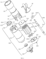
- the aforementioned driving device 20 and the blood pump 1 have at least the following advantages.
- the convex spherical surface 222 of the rotating head 220 protrudes along the axis of the rotating shaft 210 in a direction away from the connecting section 211 of the rotating shaft 210 configured to be connected to the impeller 40 and the concave spherical wall 103 of the mounting hole 102 is configured to abut against and fit with the convex spherical surface 222, the concave spherical wall 103 of the mounting hole 102 is recessed from the outside toward the inside of the receiving cavity 101 of the housing assembly 100.
- the convex spherical surface 222 protrudes towards the connecting section 211 of the rotating shaft 210 and the concave spherical wall 103 is recessed towards the connecting section 211 of the rotating shaft 210, when assembling the driving device of the conventional blood pump, the rotating shaft 210 can only be mounted on the housing assembly 100 first, and then the impeller 40 is mounted on the rotating shaft 210. In this way, it is difficult to ensure the coaxiality of the rotating shaft 210 and the impeller 40, which increases the difficulty of assembly, resulting in low production efficiency and yield of the driving device and the blood pump, and affecting the reliability of the driving device and the blood pump.
- a driving device of a blood pump according to a second embodiment is substantially the same as that of the driving device 20 according to the first embodiment, and a difference lies in that the structure of the rotating head 220 is different.
- a portion of the convex spherical surface 222 of the rotating head 220 in this embodiment is recessed to form a flow guide groove 224.
- the flow guide groove 224 extends from the bottom surface 223 of the rotating head 220 along the convex spherical surface 222 in a direction away from the bottom surface 223, and the flow guide groove 224 is in communication with the receiving cavity of the housing assembly through the communication hole 104. Specifically, the flow guide groove 224 extends from the bottom surface 224 to the top surface 225 along the convex spherical surface 222.
- the rotor is fixedly connected to the built-in section 212 of the rotating shaft 210.
- the rotating head 220 is provided with an assembly hole 228 extending from the top surface 225 of the rotating head 220 towards the bottom surface 223.
- a center axis of the assembly hole 228 passes through a center of the top surface 225 and the center of the bottom surface 223. That is, in this embodiment, the assembly hole 228 replaces the through hole 226 shown in FIG. 3 .
- One end of the built-in section 212 is accommodated in the assembly hole 228, and the other end of the built-in section 212 extends into the receiving cavity 101, for example, it is mounted on the support member.
- the driving device of the third embodiment since the structure of the driving device of the third embodiment is substantially the same as that of the driving device 20 of the first embodiment, the driving device of the third embodiment also has a similar effect to that of the driving device 20 of the first embodiment, which is not described herein again.
- a structure of a driving device of the blood pump according to a fourth embodiment is substantially the same as that of the driving device 20 according to the first embodiment, and a difference lies in that the structure of the stator is different.
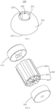
- a stator 500 includes a first stator unit 510, a second stator unit 520, and a magnetic conduction member 530.
- the first stator unit 510, the magnetic conduction member 530, and the second stator unit 520 are arranged sequentially along the axis of the rotating shaft.
- the rotating shaft is rotatably provided through the first stator unit 510, the magnetic conduction member 530, and the second stator unit 520.
- the first stator unit 510, the second stator unit 520, and the magnetic conduction member 530 are located between the first rotor unit 310 and the second rotor unit 320 shown in FIG. 4 and FIG. 8 .
- the first stator unit 510 is provided adjacent to the first rotor unit 310
- the second stator unit 520 is provided adjacent to the second rotor unit 320.
- the first stator unit 510 can drive the first rotor unit 310 to rotate
- the second stator unit 520 can drive the second rotor unit 320 to rotate.
- the first attractive force is formed between the first stator unit 510 and the first rotor unit 310
- the second attractive force is formed between the second stator unit 520 and the second rotor unit 320.
- the first stator unit 510 and the second stator unit 520 are substantially the same as the structure of the stator 400 shown in FIG. 4 .
- the first stator unit 510 includes a first magnetic core 511 and a first coil 512, and the first coil 512 is wound on the first magnetic core 511.
- the second stator unit 520 includes a second magnetic core 521 and a second coil 522 wound on the second magnetic core 521.
- the first magnetic core 511 and the second magnetic core 521 may be provided with head portions, respectively, or may not be provided with head portions.
- a difference lies in that the first stator unit 510 and the second stator unit 520 are not provided with the positioning member 430 shown in FIG. 4 .
- the first magnetic core 511 of the first stator unit 510 and the second magnetic core 521 of the second stator unit 520 are both fixedly connected to the magnetic conduction member 530.
- the first magnetic core 511 is provided with the head portion, an end of the first magnetic core 511 away from the head portion is fixedly connected to the magnetic conduction member 530, and the first rotor unit 310 is provided adjacent to the head portion of the first magnetic core 511.
- the second magnetic core 521 is provided with the head portion, an end of the second magnetic core 521 away from the head portion is fixedly connected to the magnetic conduction member 530, and the second rotor unit 320 is provided adjacent to the head portion of the second magnetic core 521.
- first magnetic core 511 In the case of the first magnetic core 511 is not provided with the head portion, one end of the first magnetic core 511 is fixedly connected to the magnetic conduction member 530, and the first rotor unit 310 is provided adjacent to the other end of the first magnetic core 511.
- second magnetic core 521 In the case of the second magnetic core 521 is not provided with the head portion, one end of the second magnetic core 521 is fixedly connected to the magnetic conduction member 530, and the second rotor unit 320 is provided adjacent to the other end of the second magnetic core 521.
- the magnetic conduction member 530 includes a first magnetic conduction plate portion 531 and a second magnetic conduction plate portion 532.
- the first magnetic conduction plate portion 531 is fixedly connected to the first magnetic core 511 of the first stator unit 510
- the second magnetic conduction plate portion 532 is fixedly connected to the second magnetic core 521 of the second stator unit 520.
- the first magnetic conduction plate portion 531 and the second magnetic conduction plate portion 532 are stacked. That is, sides of the first magnetic conduction plate portion 531 and the second magnetic conduction plate portion 532 adjacent to each other abut against each other.
- the rotating shaft is rotatably provided through the first magnetic conduction plate portion 531 and the second magnetic conduction plate portion 532.
- the first magnetic conduction plate portion 531 is fixedly connected to the second magnetic conduction plate portion 532, so that the first stator unit 510, the second stator unit 520, and the magnetic conduction member 530 formed as a whole and assembled into the housing, so that the assembly of the stator 500 is easier.
- first magnetic core 511 and the second magnetic core 521 can be easily assembled to the first magnetic conduction plate portion 531 and the second magnetic conduction plate portion 532, respectively, and the first magnetic core 511 and the second magnetic core 521 can be assembled more easily.
- the driving device of the fourth embodiment Since the structure of the driving device of the fourth embodiment is substantially the same as that of the driving device 20 of the first embodiment, the driving device of the fourth embodiment also has a similar effect to that of the driving device 20 of the first embodiment, which is not described herein again.
- the magnetic conduction back plate is configured to close a magnetic circuit, so as to promote and increase generation of magnetic flux, improve the coupling capability, and increase the magnetic flux, which helps to reduce the overall diameter of the driving device.
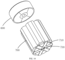
- the magnetic core 710 may have a head portion (a pole shoe) or does not have the head portion. When the magnetic core 710 has the head portion, the head portion is located at an end of the magnetic core 710 adjacent to the rotor 600.
- the support member 130 and the fixing member 140 similar to those in FIG. 2 and FIG. 4 may be omitted.
- the structure of the stator 910 may be the same as that of the stator 400 in FIG. 2 , FIG. 4 , FIG. 8 , and FIG. 9 and may alternatively be different from that of the stator 400 in FIG. 2 , FIG. 4 , FIG. 8 , and FIG. 9 .
- the stator 910 does not have the positioning member 430 in FIG. 4 and FIG. 8 , but has a magnetic conduction back plate (not shown), and the magnetic conduction back plate is fixedly connected to an end of the magnetic core 911 away from the rotor 920.
- the magnetic conduction back plate is configured to close a magnetic circuit, so as to promote and increase generation of magnetic flux, improve the coupling capability, and increase the magnetic flux, which helps to reduce the overall diameter of the driving device.
Landscapes
- Health & Medical Sciences (AREA)
- Engineering & Computer Science (AREA)
- Heart & Thoracic Surgery (AREA)
- Mechanical Engineering (AREA)
- General Health & Medical Sciences (AREA)
- Public Health (AREA)
- Biomedical Technology (AREA)
- Hematology (AREA)
- Life Sciences & Earth Sciences (AREA)
- Animal Behavior & Ethology (AREA)
- Cardiology (AREA)
- Anesthesiology (AREA)
- Veterinary Medicine (AREA)
- Vascular Medicine (AREA)
- General Engineering & Computer Science (AREA)
- Physics & Mathematics (AREA)
- Fluid Mechanics (AREA)
- Transplantation (AREA)
- Structures Of Non-Positive Displacement Pumps (AREA)
- External Artificial Organs (AREA)
Applications Claiming Priority (2)
| Application Number | Priority Date | Filing Date | Title |
|---|---|---|---|
| CN202210799477.5A CN115006717B (zh) | 2022-07-08 | 2022-07-08 | 驱动装置和血泵 |
| PCT/CN2023/098342 WO2024007791A1 (zh) | 2022-07-08 | 2023-06-05 | 驱动装置和血泵 |
Publications (2)
| Publication Number | Publication Date |
|---|---|
| EP4393537A1 true EP4393537A1 (de) | 2024-07-03 |
| EP4393537A4 EP4393537A4 (de) | 2025-09-24 |
Family
ID=83079250
Family Applications (1)
| Application Number | Title | Priority Date | Filing Date |
|---|---|---|---|
| EP23834565.6A Pending EP4393537A4 (de) | 2022-07-08 | 2023-06-05 | Antriebsvorrichtung und blutpumpe |
Country Status (4)
| Country | Link |
|---|---|
| EP (1) | EP4393537A4 (de) |
| JP (1) | JP7749265B2 (de) |
| CN (1) | CN115006717B (de) |
| WO (1) | WO2024007791A1 (de) |
Families Citing this family (1)
| Publication number | Priority date | Publication date | Assignee | Title |
|---|---|---|---|---|
| CN115006717B (zh) * | 2022-07-08 | 2026-01-02 | 深圳核心医疗科技股份有限公司 | 驱动装置和血泵 |
Family Cites Families (16)
| Publication number | Priority date | Publication date | Assignee | Title |
|---|---|---|---|---|
| KR970006929A (ko) * | 1995-07-25 | 1997-02-21 | 배순훈 | 냉각수 강제순환방식의 온수순환펌프 |
| DE102012202411B4 (de) * | 2012-02-16 | 2018-07-05 | Abiomed Europe Gmbh | Intravasale blutpumpe |
| US9144638B2 (en) * | 2013-03-14 | 2015-09-29 | Thoratec Corporation | Blood pump rotor bearings |
| JP6503301B2 (ja) * | 2013-12-27 | 2019-04-17 | テルモ株式会社 | 遠心ポンプ |
| CN105275827B (zh) * | 2014-07-21 | 2018-01-05 | 常州雷利电机科技有限公司 | 一种空调机的直流无刷排水泵及排水系统 |
| EP3574932A1 (de) * | 2018-05-28 | 2019-12-04 | Berlin Heart GmbH | Blutpumpe |
| CN112689716B (zh) * | 2018-10-18 | 2023-06-30 | 波士顿科学国际有限公司 | 血泵轴轴承 |
| EP3711787A1 (de) * | 2019-03-19 | 2020-09-23 | Abiomed Europe GmbH | Blutpumpe |
| CN111840683B (zh) | 2020-07-31 | 2024-11-26 | 深圳核心医疗科技股份有限公司 | 介入式心室辅助装置 |
| US20220161021A1 (en) * | 2020-11-20 | 2022-05-26 | Kardion Gmbh | Mechanical circulatory support system with insertion tool |
| CN112472999B (zh) | 2020-12-22 | 2025-03-21 | 深圳核心医疗科技股份有限公司 | 血泵 |
| CN112587792B (zh) * | 2020-12-22 | 2024-08-27 | 深圳核心医疗科技股份有限公司 | 血泵 |
| CN215025224U (zh) * | 2020-12-22 | 2021-12-07 | 深圳核心医疗科技有限公司 | 血泵 |
| CN215653408U (zh) * | 2020-12-23 | 2022-01-28 | 上海微创心力医疗科技有限公司 | 轴承、血泵以及心室辅助循环装置 |
| CN216111292U (zh) * | 2021-01-26 | 2022-03-22 | 汉宇集团股份有限公司 | 一种电动机轴二端各传动一泵结构的屏蔽电泵 |
| CN115006717B (zh) * | 2022-07-08 | 2026-01-02 | 深圳核心医疗科技股份有限公司 | 驱动装置和血泵 |
-
2022
- 2022-07-08 CN CN202210799477.5A patent/CN115006717B/zh active Active
-
2023
- 2023-06-05 JP JP2024529979A patent/JP7749265B2/ja active Active
- 2023-06-05 EP EP23834565.6A patent/EP4393537A4/de active Pending
- 2023-06-05 WO PCT/CN2023/098342 patent/WO2024007791A1/zh not_active Ceased
Also Published As
| Publication number | Publication date |
|---|---|
| CN115006717A (zh) | 2022-09-06 |
| EP4393537A4 (de) | 2025-09-24 |
| JP2024539468A (ja) | 2024-10-28 |
| CN115006717B (zh) | 2026-01-02 |
| JP7749265B2 (ja) | 2025-10-06 |
| WO2024007791A1 (zh) | 2024-01-11 |
Similar Documents
| Publication | Publication Date | Title |
|---|---|---|
| EP4520388A1 (de) | Antriebsvorrichtung und blutpumpe | |
| CN115414591B (zh) | 驱动装置和血泵 | |
| EP4477252A1 (de) | Antriebsvorrichtung und blutpumpe | |
| WO2023160422A1 (zh) | 血泵及其驱动装置 | |
| EP4316566A1 (de) | Blutpumpe und antriebsvorrichtung dafür | |
| CN215025224U (zh) | 血泵 | |
| US12521544B2 (en) | Driving apparatus and blood pump | |
| EP4299103A1 (de) | Blutpumpe und antriebsvorrichtung dafür | |
| JP2025521309A (ja) | 駆動装置及び血液ポンプ | |
| CN115282467B (zh) | 驱动机构和血泵 | |
| US20250195868A1 (en) | Driving mechanism and blood pump | |
| EP4537890A1 (de) | Antriebsvorrichtung und blutpumpe | |
| JP7749265B2 (ja) | 駆動装置及び血液ポンプ | |
| EP4563186A1 (de) | Antriebsvorrichtung und blutpumpe | |
| CN115192894B (zh) | 驱动装置及血泵 |
Legal Events
| Date | Code | Title | Description |
|---|---|---|---|
| STAA | Information on the status of an ep patent application or granted ep patent |
Free format text: STATUS: THE INTERNATIONAL PUBLICATION HAS BEEN MADE |
|
| PUAI | Public reference made under article 153(3) epc to a published international application that has entered the european phase |
Free format text: ORIGINAL CODE: 0009012 |
|
| STAA | Information on the status of an ep patent application or granted ep patent |
Free format text: STATUS: REQUEST FOR EXAMINATION WAS MADE |
|
| 17P | Request for examination filed |
Effective date: 20240328 |
|
| AK | Designated contracting states |
Kind code of ref document: A1 Designated state(s): AL AT BE BG CH CY CZ DE DK EE ES FI FR GB GR HR HU IE IS IT LI LT LU LV MC ME MK MT NL NO PL PT RO RS SE SI SK SM TR |
|
| A4 | Supplementary search report drawn up and despatched |
Effective date: 20250827 |
|
| RIC1 | Information provided on ipc code assigned before grant |
Ipc: A61M 60/81 20210101AFI20250821BHEP Ipc: A61M 60/139 20210101ALI20250821BHEP Ipc: A61M 60/216 20210101ALI20250821BHEP Ipc: A61M 60/802 20210101ALI20250821BHEP Ipc: A61M 60/857 20210101ALI20250821BHEP Ipc: F04D 29/047 20060101ALI20250821BHEP Ipc: F04D 29/057 20060101ALI20250821BHEP Ipc: A61M 60/13 20210101ALI20250821BHEP Ipc: A61M 60/221 20210101ALI20250821BHEP Ipc: A61M 60/416 20210101ALI20250821BHEP Ipc: A61M 60/422 20210101ALI20250821BHEP Ipc: A61M 60/824 20210101ALI20250821BHEP Ipc: A61M 60/825 20210101ALI20250821BHEP Ipc: A61M 60/829 20210101ALI20250821BHEP Ipc: F04D 29/046 20060101ALI20250821BHEP |
|
| DAV | Request for validation of the european patent (deleted) | ||
| DAX | Request for extension of the european patent (deleted) |