EP4393577A1 - Dispositif à membrane pour régler le débit de matière granulaire et granulateur - Google Patents
Dispositif à membrane pour régler le débit de matière granulaire et granulateur Download PDFInfo
- Publication number
- EP4393577A1 EP4393577A1 EP23216638.9A EP23216638A EP4393577A1 EP 4393577 A1 EP4393577 A1 EP 4393577A1 EP 23216638 A EP23216638 A EP 23216638A EP 4393577 A1 EP4393577 A1 EP 4393577A1
- Authority
- EP
- European Patent Office
- Prior art keywords
- diaphragm apparatus
- edge
- granular material
- opening
- closing element
- Prior art date
- Legal status (The legal status is an assumption and is not a legal conclusion. Google has not performed a legal analysis and makes no representation as to the accuracy of the status listed.)
- Pending
Links
- 239000008187 granular material Substances 0.000 title claims abstract description 62
- 230000001105 regulatory effect Effects 0.000 title claims description 6
- 239000012528 membrane Substances 0.000 claims description 28
- 238000005054 agglomeration Methods 0.000 claims description 6
- 230000002776 aggregation Effects 0.000 claims description 6
- 239000012254 powdered material Substances 0.000 claims description 6
- 238000007599 discharging Methods 0.000 claims description 4
- 238000005469 granulation Methods 0.000 description 17
- 230000003179 granulation Effects 0.000 description 17
- 239000000463 material Substances 0.000 description 17
- 239000002245 particle Substances 0.000 description 10
- 238000010168 coupling process Methods 0.000 description 9
- 238000005859 coupling reaction Methods 0.000 description 9
- 238000004519 manufacturing process Methods 0.000 description 9
- 230000008878 coupling Effects 0.000 description 8
- 238000004140 cleaning Methods 0.000 description 6
- 238000012423 maintenance Methods 0.000 description 6
- 238000003825 pressing Methods 0.000 description 6
- 238000009826 distribution Methods 0.000 description 5
- 238000009825 accumulation Methods 0.000 description 4
- 230000003247 decreasing effect Effects 0.000 description 4
- 238000000034 method Methods 0.000 description 4
- 230000008569 process Effects 0.000 description 4
- 238000010276 construction Methods 0.000 description 3
- 230000002093 peripheral effect Effects 0.000 description 3
- 230000007423 decrease Effects 0.000 description 2
- 238000006073 displacement reaction Methods 0.000 description 2
- 238000009434 installation Methods 0.000 description 2
- 239000007769 metal material Substances 0.000 description 2
- 230000009471 action Effects 0.000 description 1
- 239000003905 agrochemical Substances 0.000 description 1
- 239000000919 ceramic Substances 0.000 description 1
- 230000008859 change Effects 0.000 description 1
- 230000001276 controlling effect Effects 0.000 description 1
- 239000000203 mixture Substances 0.000 description 1
- 239000000843 powder Substances 0.000 description 1
Images


Classifications
-
- B—PERFORMING OPERATIONS; TRANSPORTING
- B01—PHYSICAL OR CHEMICAL PROCESSES OR APPARATUS IN GENERAL
- B01J—CHEMICAL OR PHYSICAL PROCESSES, e.g. CATALYSIS OR COLLOID CHEMISTRY; THEIR RELEVANT APPARATUS
- B01J4/00—Feed or outlet devices; Feed or outlet control devices
- B01J4/001—Feed or outlet devices as such, e.g. feeding tubes
-
- B—PERFORMING OPERATIONS; TRANSPORTING
- B01—PHYSICAL OR CHEMICAL PROCESSES OR APPARATUS IN GENERAL
- B01F—MIXING, e.g. DISSOLVING, EMULSIFYING OR DISPERSING
- B01F29/00—Mixers with rotating receptacles
- B01F29/25—Mixers with rotating receptacles with material flowing continuously through the receptacles from inlet to discharge
-
- B—PERFORMING OPERATIONS; TRANSPORTING
- B01—PHYSICAL OR CHEMICAL PROCESSES OR APPARATUS IN GENERAL
- B01F—MIXING, e.g. DISSOLVING, EMULSIFYING OR DISPERSING
- B01F35/00—Accessories for mixers; Auxiliary operations or auxiliary devices; Parts or details of general application
- B01F35/75—Discharge mechanisms
- B01F35/754—Discharge mechanisms characterised by the means for discharging the components from the mixer
- B01F35/75435—Discharge mechanisms characterised by the means for discharging the components from the mixer using means for discharging the mixture in a pulsating or intermittent manner
-
- B—PERFORMING OPERATIONS; TRANSPORTING
- B01—PHYSICAL OR CHEMICAL PROCESSES OR APPARATUS IN GENERAL
- B01J—CHEMICAL OR PHYSICAL PROCESSES, e.g. CATALYSIS OR COLLOID CHEMISTRY; THEIR RELEVANT APPARATUS
- B01J2/00—Processes or devices for granulating materials, e.g. fertilisers in general; Rendering particulate materials free flowing in general, e.g. making them hydrophobic
- B01J2/12—Processes or devices for granulating materials, e.g. fertilisers in general; Rendering particulate materials free flowing in general, e.g. making them hydrophobic in rotating drums
-
- B—PERFORMING OPERATIONS; TRANSPORTING
- B01—PHYSICAL OR CHEMICAL PROCESSES OR APPARATUS IN GENERAL
- B01J—CHEMICAL OR PHYSICAL PROCESSES, e.g. CATALYSIS OR COLLOID CHEMISTRY; THEIR RELEVANT APPARATUS
- B01J4/00—Feed or outlet devices; Feed or outlet control devices
- B01J4/001—Feed or outlet devices as such, e.g. feeding tubes
- B01J4/007—Feed or outlet devices as such, e.g. feeding tubes provided with moving parts
-
- B—PERFORMING OPERATIONS; TRANSPORTING
- B01—PHYSICAL OR CHEMICAL PROCESSES OR APPARATUS IN GENERAL
- B01J—CHEMICAL OR PHYSICAL PROCESSES, e.g. CATALYSIS OR COLLOID CHEMISTRY; THEIR RELEVANT APPARATUS
- B01J4/00—Feed or outlet devices; Feed or outlet control devices
- B01J4/008—Feed or outlet control devices
-
- B—PERFORMING OPERATIONS; TRANSPORTING
- B01—PHYSICAL OR CHEMICAL PROCESSES OR APPARATUS IN GENERAL
- B01J—CHEMICAL OR PHYSICAL PROCESSES, e.g. CATALYSIS OR COLLOID CHEMISTRY; THEIR RELEVANT APPARATUS
- B01J4/00—Feed or outlet devices; Feed or outlet control devices
- B01J4/02—Feed or outlet devices; Feed or outlet control devices for feeding measured, i.e. prescribed quantities of reagents
-
- B—PERFORMING OPERATIONS; TRANSPORTING
- B01—PHYSICAL OR CHEMICAL PROCESSES OR APPARATUS IN GENERAL
- B01J—CHEMICAL OR PHYSICAL PROCESSES, e.g. CATALYSIS OR COLLOID CHEMISTRY; THEIR RELEVANT APPARATUS
- B01J4/00—Feed or outlet devices; Feed or outlet control devices
- B01J4/04—Feed or outlet devices; Feed or outlet control devices using osmotic pressure using membranes, porous plates
-
- B—PERFORMING OPERATIONS; TRANSPORTING
- B01—PHYSICAL OR CHEMICAL PROCESSES OR APPARATUS IN GENERAL
- B01J—CHEMICAL OR PHYSICAL PROCESSES, e.g. CATALYSIS OR COLLOID CHEMISTRY; THEIR RELEVANT APPARATUS
- B01J8/00—Chemical or physical processes in general, conducted in the presence of fluids and solid particles; Apparatus for such processes
- B01J8/0015—Feeding of the particles in the reactor; Evacuation of the particles out of the reactor
Definitions
- control of the process parameters and in particular the granulation time is of fundamental importance.
- control the size and quality of the granules exiting from a granulating machine it is possible to control the size and quality of the granules exiting from a granulating machine.
- An object of the invention is to improve the prior art apparatuses for dispensing granular material.
- a further object is to provide an apparatus for dispensing granular material shaped so as to reduce cleaning and maintenance operations.
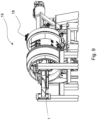
- Figures 9 and 10 further show the granulating machine 19 for producing granular material by agglomeration of powdered material.
- the granulating machine 19 comprises a rotatable drum 18 with a horizontal axis A provided with an open discharge end for discharging the granular material, the open discharge end is provided with the diaphragm apparatus 1 described below.
- the diaphragm apparatus 1 is fixed - in use - with respect to a rotation of the rotatable drum 18.
- the rotatable drum 18 - in use - rotates around the horizontal axis A, while the diaphragm apparatus 1 is fixed with respect to the rotation of the rotatable drum 18, i.e. the diaphragm apparatus 1 is stationary.
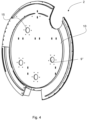
- the diaphragm apparatus 1 comprises a wall 2 having a substantially circular plan shape; in use, the wall 2 has the function of containing the material present inside the rotatable drum 18. On wall 2 there is obtained an opening 3 intended to discharge the granular material from the granulating machine 19. The opening 3 may circumferentially interrupt the material continuity of wall 2.
- the wall 2 extends over two main dimensions with respect to a third dimension (the thickness).
- the wall 2 has a substantially circular plan shape with a circle radius R.
- the opening 3 comprises a first edge 4 and a second edge 5.
- the first edge 4 and the second edge 5 are opposite to each other.
- the opening 3 may extend in a circular crown arc between the first edge 4 and the second edge 5.
- the opening 3 may extend in a circular crown arc having a first major radius R' equal to the circle radius R, and a first minor radius R" smaller than the circle radius R.
- first edge 4 and the second edge 5 may extend on the wall 2 along a direction substantially radial to the substantially circular plan shape.
- the first edge 4 and the second edge 5 may extend along a section whose size is equal to the difference of the first major radius R' and of the first minor radius R".
- the first edge 4 and the second edge 5 can be the radial sides of the opening 3.
- the closing element 6 does not entirely occupy the area of the opening 3 in the closed position PC. Therefore, in the closed position PC, the end 7 is not in contact with the first edge 4 so as to allow a small amount of granular material to pass through the rotatable drum 18.
- the closing element 6 is removably couplable with the wall 2.
- the closing element 6 may be coupled using coupling means 17, such as for example threaded coupling means, quick coupling means, and the like.
- the coupling means 17 may comprise holes and/or slots.
- the closing element 6 may be fixed in one or more intermediate positions comprised between the open position PA and the closed position PC. More particularly, both the wall 2 and the closing element 6 may comprise one or more holes and/or slots which allow the coupling of closing element 6 with wall 2 and the fixing of closing element 6 in one or more intermediate positions between the closed position PC and the open position PA. Therefore, the closing element 6 can be coupled to the wall 2 in order to easily and quickly adjust the area of the opening 3 for the discharge of the granular material; this allows to regulate the material output flow rate output and as a result the granulation time (that is the time within which the powdered material is granulated inside the rotatable drum 18).
- fixing the closing element 6 with the end 7 arranged in a position closer to the first edge 4 allows to reduce the material output flow rate, increasing the granulation time and particle size of the granular material produced; fixing the closing element 6 with the end 7 arranged closest to the second edge 5 allows to increase the material output flow rate, decreasing the granulation time and the particle size of the granular material produced.
- decreasing the area of the opening 3 increases the granulation time and the particle size of the granular material produced; increasing the area of the opening 3 decreases the granulation time and the particle size of the granular material produced.
- the closing element 6 may be fixed and made to flow manually on the wall 2 between the closed position PC and the open position PA.
- the closing element 6 may comprise a deviating element 12.
- the deviating element is arranged closest to the end 7 and it extends transversely to the closing element 6.
- the deviating element 12 protrudes from the closing element 6 towards the internal of the rotatable drum 18 and it facilitates the exit of the granular material.
- the deviating element 12 is configured to guide the granular material towards the outlet.
- the deviating element 12 extends transversely to the closing element 6 to induce, in use, the granulated material to pass through the opening 3; as a matter of fact, during the rotation of the rotatable drum 18, the granular material comes into contact with the deviating element 12 and slides thereon towards the external of the rotatable drum 18 through the opening 3.
- the deviating element 12 is tilted by an angle ⁇ with respect to a reference plane P on which the closing element 6 lies to facilitate the exit of the granular material through the opening 3.
- the angle ⁇ is comprised between 90 and 140 sexagesimal degrees.
- the wall 2 may comprise a frame 8.
- the peripheral edges of the membrane element 9 may be fixed to the frame 8.
- the peripheral edges of the membrane element 9 may be fixed to the frame 8 by means of a threaded coupling, snap-coupling, interference coupling or another type of coupling.
- the frame 8 may be made of a rigid material, with properties that enable it to appropriately support the membrane element 9.
- the frame 8 may be made of metal material.
- the wall 2 further comprises a plate 10 facing the second face 9".
- the plate 10 comprises an outer face 10' facing in use toward the external of the rotatable drum 18.
- the plate 10 comprises a further face, opposite to the outer face 10', facing the second face 9".
- the plate 10 may be made of a rigid material, for example with a metal material.
- the plate 10 is arranged to limit an axial deformation displacement of membrane element 9 along an axis substantially parallel to the horizontal axis A. In other words, the plate 10 prevents, in use, an axial displacement of the membrane element 9 directed towards the external of the rotatable drum 18 and, therefore, towards the plate 10.
- the urging action exerted by means of the urging device 11 deforms the elastic membrane element 9 preventing the granular material from adhering to the first face 9'.
- the diaphragm apparatus 1 is therefore kept clean given that the accumulation of granular material on the membrane element 9 is limited. Therefore, the urge exerted by the urging device 11 on the membrane element 9 allows to drastically reduce cleaning and maintenance operations.
- the urging device 11 comprises a pressing head 16 arranged to press the second face 9" in a limited area thereof and cause local deformation of the membrane element 9.
- the present invention it is possible to control the granulation time easily and effectively.
- the possibility to adjust the opening area for the discharge of the granular material allows to regulate the flow and the flow rate of the material exiting from a granulating machine, therefore controlling the granulation time and the particle size distribution of the granules obtained.
- the closing element which may be fixed by changing its position between the closed position and the open position so as to control the opening area for discharging the granular material, increasing or decreasing, the material output flow rate and consequently changing the granulation time and particle size distribution depending on the production needs.
- the apparatus according to the present invention allows to reduce maintenance and manual cleaning operations, reducing machine downtime and production costs.
- the membrane element and the urging devices which urge the membrane element allow to limit the accumulation of the material on the wall.
- the urging devices clean the membrane element and, therefore, cleaning and maintenance operations are limited, with significant saving in terms of time and costs.
- the apparatus according to the present invention also facilitates construction, transportation and assembly operations.
- construction, transportation and assembly operations are simplified, and the space occupied by the granulating machine during the granulating process is reduced.
Landscapes
- Chemical & Material Sciences (AREA)
- Chemical Kinetics & Catalysis (AREA)
- Organic Chemistry (AREA)
- Filling Or Emptying Of Bunkers, Hoppers, And Tanks (AREA)
Applications Claiming Priority (1)
| Application Number | Priority Date | Filing Date | Title |
|---|---|---|---|
| IT102022000027267A IT202200027267A1 (it) | 2022-12-30 | 2022-12-30 | Apparato a diaframma per regolare un flusso di materiale in granuli e macchina di granulazione |
Publications (1)
| Publication Number | Publication Date |
|---|---|
| EP4393577A1 true EP4393577A1 (fr) | 2024-07-03 |
Family
ID=85685806
Family Applications (1)
| Application Number | Title | Priority Date | Filing Date |
|---|---|---|---|
| EP23216638.9A Pending EP4393577A1 (fr) | 2022-12-30 | 2023-12-14 | Dispositif à membrane pour régler le débit de matière granulaire et granulateur |
Country Status (3)
| Country | Link |
|---|---|
| EP (1) | EP4393577A1 (fr) |
| CN (1) | CN118267929A (fr) |
| IT (1) | IT202200027267A1 (fr) |
Citations (6)
| Publication number | Priority date | Publication date | Assignee | Title |
|---|---|---|---|---|
| US2603832A (en) * | 1951-06-20 | 1952-07-22 | Noranda Mines Ltd | Rotary drum apparatus and means for preventing material being treated from accumulating thereon |
| US3298620A (en) * | 1963-03-25 | 1967-01-17 | Tecnopatent S A | Casing with pulsating internal wall for mills, mixers and similar equipment |
| US3564083A (en) * | 1968-03-27 | 1971-02-16 | Brevets Granofibre Sebreg Soc | Formation of fibrous granules |
| US4674198A (en) * | 1986-03-17 | 1987-06-23 | Huettlin Herbert | Apparatus for granulating, pelleting, and coating and/or drying fluid materials |
| CN205109560U (zh) * | 2015-11-09 | 2016-03-30 | 山东中创亿丰肥料集团有限公司 | 生物有机肥转鼓造粒机 |
| CN209109127U (zh) * | 2018-11-01 | 2019-07-16 | 周口万德生物有机肥有限公司 | 一种复合肥造粒机 |
-
2022
- 2022-12-30 IT IT102022000027267A patent/IT202200027267A1/it unknown
-
2023
- 2023-12-14 EP EP23216638.9A patent/EP4393577A1/fr active Pending
- 2023-12-27 CN CN202311810318.1A patent/CN118267929A/zh active Pending
Patent Citations (6)
| Publication number | Priority date | Publication date | Assignee | Title |
|---|---|---|---|---|
| US2603832A (en) * | 1951-06-20 | 1952-07-22 | Noranda Mines Ltd | Rotary drum apparatus and means for preventing material being treated from accumulating thereon |
| US3298620A (en) * | 1963-03-25 | 1967-01-17 | Tecnopatent S A | Casing with pulsating internal wall for mills, mixers and similar equipment |
| US3564083A (en) * | 1968-03-27 | 1971-02-16 | Brevets Granofibre Sebreg Soc | Formation of fibrous granules |
| US4674198A (en) * | 1986-03-17 | 1987-06-23 | Huettlin Herbert | Apparatus for granulating, pelleting, and coating and/or drying fluid materials |
| CN205109560U (zh) * | 2015-11-09 | 2016-03-30 | 山东中创亿丰肥料集团有限公司 | 生物有机肥转鼓造粒机 |
| CN209109127U (zh) * | 2018-11-01 | 2019-07-16 | 周口万德生物有机肥有限公司 | 一种复合肥造粒机 |
Also Published As
| Publication number | Publication date |
|---|---|
| CN118267929A (zh) | 2024-07-02 |
| IT202200027267A1 (it) | 2024-06-30 |
Similar Documents
| Publication | Publication Date | Title |
|---|---|---|
| EP0721802B1 (fr) | Module de cavité réduite à siège interchangeable | |
| US6834816B2 (en) | Selected range arc settable spray nozzle with pre-set proportional connected upstream flow throttling | |
| CN101298068B (zh) | 带有可调整的弧、流量和水流角度的喷洒装置头喷嘴组件 | |
| US4111626A (en) | Powder compacting machine | |
| US4290989A (en) | Method and apparatus for extruding a plurality of ribbons | |
| US7249696B2 (en) | Pneumatic liquid-dispensing gun | |
| KR102490656B1 (ko) | 여과 장치 및 여과 장치의 필터 요소로부터 오물 입자를 제거하기 위한 세척 유닛 | |
| US20090026297A1 (en) | Powder Based Granules Disintegrating And Sizing Device | |
| EP4393577A1 (fr) | Dispositif à membrane pour régler le débit de matière granulaire et granulateur | |
| EP2818235B1 (fr) | Appareil de dosage | |
| JP2009509876A (ja) | 所要量の粉体状またはペースト状の材料物質を供給するためのディスペンサ・デバイス | |
| US3346412A (en) | Tire coating apparatus | |
| JP2018507781A (ja) | 粒状体を製造する装置 | |
| WO1999016540A2 (fr) | Melangeur a ecoulement longitudinal | |
| CN115213056A (zh) | 一种涂布条数与宽度可控的狭缝涂布槽模头 | |
| JPH0417847B2 (fr) | ||
| JPH0226522B2 (fr) | ||
| US5820675A (en) | Application unit for directly or indirectly applying a fluid or pasty medium to a continuous material web | |
| US4297210A (en) | Centrifugal separator | |
| BR102023027726A2 (pt) | Aparelho de diafragma e máquina de granular para produção de material granulado por aglomeração de material em pó | |
| US12145126B2 (en) | Unit and method for producing and treating granulate, and adapter connection piece for connecting a granulator which generates a granulate and a fluidizing apparatus | |
| EP1022221B1 (fr) | Dispositif pour distribuer des volumes prédéterminés d'un matériau poudreux | |
| US3506238A (en) | Flow control for flowable mediums | |
| JPH0144949B2 (fr) | ||
| CN121016605B (zh) | 一种挤压制粒机 |
Legal Events
| Date | Code | Title | Description |
|---|---|---|---|
| PUAI | Public reference made under article 153(3) epc to a published international application that has entered the european phase |
Free format text: ORIGINAL CODE: 0009012 |
|
| STAA | Information on the status of an ep patent application or granted ep patent |
Free format text: STATUS: THE APPLICATION HAS BEEN PUBLISHED |
|
| AK | Designated contracting states |
Kind code of ref document: A1 Designated state(s): AL AT BE BG CH CY CZ DE DK EE ES FI FR GB GR HR HU IE IS IT LI LT LU LV MC ME MK MT NL NO PL PT RO RS SE SI SK SM TR |
|
| STAA | Information on the status of an ep patent application or granted ep patent |
Free format text: STATUS: REQUEST FOR EXAMINATION WAS MADE |
|
| 17P | Request for examination filed |
Effective date: 20241224 |