EP4393620A1 - Insert tournant - Google Patents
Insert tournant Download PDFInfo
- Publication number
- EP4393620A1 EP4393620A1 EP22217209.0A EP22217209A EP4393620A1 EP 4393620 A1 EP4393620 A1 EP 4393620A1 EP 22217209 A EP22217209 A EP 22217209A EP 4393620 A1 EP4393620 A1 EP 4393620A1
- Authority
- EP
- European Patent Office
- Prior art keywords
- support surfaces
- insert
- secondary support
- main
- turning insert
- Prior art date
- Legal status (The legal status is an assumption and is not a legal conclusion. Google has not performed a legal analysis and makes no representation as to the accuracy of the status listed.)
- Pending
Links
Images


Classifications
-
- B—PERFORMING OPERATIONS; TRANSPORTING
- B23—MACHINE TOOLS; METAL-WORKING NOT OTHERWISE PROVIDED FOR
- B23B—TURNING; BORING
- B23B27/00—Tools for turning or boring machines; Tools of a similar kind in general; Accessories therefor
- B23B27/14—Cutting tools of which the bits or tips or cutting inserts are of special material
- B23B27/16—Cutting tools of which the bits or tips or cutting inserts are of special material with exchangeable cutting bits or cutting inserts, e.g. able to be clamped
- B23B27/1644—Cutting tools of which the bits or tips or cutting inserts are of special material with exchangeable cutting bits or cutting inserts, e.g. able to be clamped with plate-like cutting inserts of special shape clamped by a clamping member acting almost perpendicularly on the chip-forming plane and at the same time upon the wall of a hole in the cutting insert
-
- B—PERFORMING OPERATIONS; TRANSPORTING
- B23—MACHINE TOOLS; METAL-WORKING NOT OTHERWISE PROVIDED FOR
- B23B—TURNING; BORING
- B23B2200/00—Details of cutting inserts
- B23B2200/04—Overall shape
- B23B2200/049—Triangular
- B23B2200/0495—Triangular rounded
-
- B—PERFORMING OPERATIONS; TRANSPORTING
- B23—MACHINE TOOLS; METAL-WORKING NOT OTHERWISE PROVIDED FOR
- B23B—TURNING; BORING
- B23B2200/00—Details of cutting inserts
- B23B2200/08—Rake or top surfaces
- B23B2200/082—Rake or top surfaces with elevated clamping surface
-
- B—PERFORMING OPERATIONS; TRANSPORTING
- B23—MACHINE TOOLS; METAL-WORKING NOT OTHERWISE PROVIDED FOR
- B23B—TURNING; BORING
- B23B2200/00—Details of cutting inserts
- B23B2200/12—Side or flank surfaces
- B23B2200/125—Side or flank surfaces discontinuous
-
- B—PERFORMING OPERATIONS; TRANSPORTING
- B23—MACHINE TOOLS; METAL-WORKING NOT OTHERWISE PROVIDED FOR
- B23B—TURNING; BORING
- B23B2200/00—Details of cutting inserts
- B23B2200/12—Side or flank surfaces
- B23B2200/128—Side or flank surfaces with one or more grooves
-
- B—PERFORMING OPERATIONS; TRANSPORTING
- B23—MACHINE TOOLS; METAL-WORKING NOT OTHERWISE PROVIDED FOR
- B23B—TURNING; BORING
- B23B2205/00—Fixation of cutting inserts in holders
- B23B2205/12—Seats for cutting inserts
-
- B—PERFORMING OPERATIONS; TRANSPORTING
- B23—MACHINE TOOLS; METAL-WORKING NOT OTHERWISE PROVIDED FOR
- B23B—TURNING; BORING
- B23B2205/00—Fixation of cutting inserts in holders
- B23B2205/16—Shims
Definitions
- the present invention relates to a double sided, negative turning insert, turning tool body for holding such a turning insert and to a turning tool comprising such a tuning insert.
- the top surface and the bottom surface have a basic triangular shape, wherein, for example, the corners are rounded or sharp, the sides extend inwards or outwards towards a center between the corners or connects in a straight or substantially straight line.
- the sides are straight and linear, convexly or concavely curved, or comprise alternating portions thereof.
- the side surface as seen in cross sections parallel to the central plane, optionally has a corresponding shape in some of the cross sections.
- both the top surface and the bottom surface include portions closest to the cutting edges that form rake surfaces.
- the top surface or the bottom surface include chip breakers, for example in form of protrusions or recesses.
- the top surface comprises a main top support surface and the bottom surface comprises a main bottom support surface. These surfaces are configured to cooperate with corresponding surfaces in an insert seat to provide at least a major portion of the support in a direction normal to the central plane. Preferably, the main top and the main bottom support surfaces are parallel with the central plane. Depending on the index position the cutting insert, one of the main top support surface and the main bottom support surface cooperate with a main seat support surface in an insert seat and the other one of the main top support surface and the main bottom support surface cooperate with a clamping mechanism.
- the clamping mechanism is a clamping screw, a clamp, a resilient member of the turning tool body, or any other suitable mechanism.
- the turning insert has a central, through hole for the clamping screw.
- the peripheral side surface comprises in total three main side surfaces.
- the peripheral side surfaces comprises no more and no less than the three main side surfaces.
- Each of the main side surfaces extend from a respective associated first to a respective associated second of the corner side surfaces along a respective associated one of the three sides of the imaginary triangle.
- the main side surface extends along the associated side of the imaginary triangle by optionally being aligned therewith, or by having a main extension in the direction of the associated side while deviating therefrom inwards and/or outwards.
- the secondary support surfaces of the pair each form a respective end wall of a recess, wherein the end walls are arranged in a common, single recess, or in one respective recess.
- each end wall is located close the corner side surface and the recess extends toward a midpoint half way between the corner side surfaces.
- a position of the secondary support surface close to the corner side surfaces is advantageous for countering transverse cutting forces acting to displace the turning insert in an insert seat.
- a single recess may extend from close to the respective associated first to close to the respective associated second of the corner side surfaces.
- the secondary support surfaces of the pair are preferably identical.
- each of the part-surfaces comprise a surface limited by the top surface, the bottom surface, the associated secondary support surface, and a thereto closest one of the first and second associated corner side surfaces.
- the primary support surface covers an area between the side corner surface and a closest one of the secondary support surfaces in the pair.
- the turning insert has main support closest to the corners where cutting forces are most effectively countered.
- corner cutting edges are provided at the top surface and at the bottom surface in one of the thee corners only, and the main side surface that is opposite to that corner constitutes the at least one main side surface comprising the primary and the secondary support surfaces.
- the imaginary triangle is equilateral.
- the imaginary triangle is instead an isosceles triangle.
- the turning insert comprises one set of primary support surfaces for each index position, whereas the insert seat comprises a single set of support surfaces for cooperation with one set of the support surfaces of the turning insert at a time.
- each set of support surfaces of the turning insert includes one of the main top surface and the main bottom surface to cooperate with the main seat support surface, a portion of the other one of the main top surface and the main bottom surface to cooperate with a clamping mechanism, the primary support surfaces and the secondary support surfaces of the at least one main side surface for cooperation with the primary support surfaces and secondary support surfaces of the insert seat.
- the turning insert and the turning body together with a clamping mechanism form a turning tool, wherein the turning insert is mounted and clamped in the insert seat of the turning body by the clamping mechanism.
- the main seat support surface of the insert seat faces the main bottom support surface of the turning insert
- the primary support surfaces of the insert seat face a respective one of the primary support surfaces of the at least one of the three main side surfaces of the turning insert
- the pair of secondary support surfaces of the turning tool body pair face a respective one of the secondary support surfaces of the pair of the at least one main side surface of the turning insert.
- the cooperating main support surfaces and primary support surfaces are firmly pressed against each other, while the secondary support surfaces provide secondary support in case it is needed.
- the turning insert is guided to a desired position and fixed therein by the cooperating main and primary support surfaces, wherein the pairs of secondary support surfaces are in a standby position.
- the secondary support surfaces are separated from each other by a small gap, or contact each other without pressing against each other.
- the gap is up to 0,1 mm.
- cutting forces act on the turning insert in a direction parallel to the associated side of the imaginary triangle, they may strive to displace the turning insert in the insert seat. This may push the turning insert in the insert seat such that cooperating secondary support surface from the pair of the turning insert and the insert seat assume an active position by engaging and pressing against in each other.
- the secondary support surfaces provide secondary support in case it is need such that the turning insert is able to withstand higher cutting forces and/or cutting forces from more directions than prior art turning inserts.
- the turning insert comprises a coated body of cemented carbide.
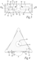
- the body comprises a top surface 1, a bottom surface 2 and a peripheral side surface 3 connecting the top surface 1 and the bottom surface 2.
- the peripheral side surface 3 comprises in total three corner side surfaces 4 and in total three main side surfaces 5.
- a central plane as indicated in Fig. 3 and shown in Fig. 4 extends half way between the top surface 1 and the bottom surface 2.
- the body of the turning insert has a central, through hole 16.
- a central axis 12 is both a central axis of the hole 16 and of the body and, extends in a direction normal to the central plane.
- the body of the example embodiment has two times 120° symmetry, such that the top surface 1 and the bottom surface 2 are identical to each other, and such that the three main side surfaces 3 also are identical to each other. Furthermore, all six corner cutting edges 6 are identical to each other providing for six index potions of the turning insert.
- the body has a 180° symmetry around an axis in the central plane, and a 120° symmetry around the central axis 12.
- the turning insert is double-sided.
- a first corner cutting edge 6 is symmetrical over a bisector 9, c.f. Fig. 2 .
- the corner cutting edge 6 comprises a convex nose cutting edge 7, and two straight main cutting edges 8 extending therefrom on one respective side thereof.
- the main cutting edges 8 form a nose angle ⁇ of 71-85°.
- the bisector 9 extends half way between the two main cutting edges 8 and intersects a most distal point 11 of the corner cutting edge 6.
- Both the top surface 1 and the bottom surface 2 include portions closest to the cutting edges that form rake surfaces.
- the rake surfaces are provided with chip breakers in form of grooves 17.
- the top surface 1 comprises a main top support surface 14 and the bottom surface 2 comprises a main bottom support surface 15, c.f. Fig. 3 .
- the main support surfaces 14, 15 both constitute continuous surfaces which extend from an edge of the central hole 16 to the grooves 17.
- each corner side surface 4 is arranged in one respective corner of an imaginary triangle 10 having three sides.
- the imaginary triangle 10 is equilateral and each corner is arranged at the most distal point 11 of each respective corner cutting edge 6.
- Each most distal point 11, which also is a corner of the imaginary triangle, has the same distance to a central axis 12.
- Each main side surface 5 has an extension along an associated one of the three sides of the imaginary triangle 10.
- Each main side surface 5 extends outward from the associated side of the imaginary triangle 10 closest to the corner side surface, and inward from the associated side at a central portion between the corner side surfaces 4.
- main side surfaces 5 In the following, only one of the main side surfaces 5 will be described. Thanks to the symmetry, the other main side surfaces 5 comprise the same features.
- the main side surface 5 comprises primary support surfaces 13 in form of two separate part-surfaces. Both part-surfaces are planar, and, as can be seen in Fig. 4 , form an angle ⁇ of 165 °. Between the two part-surfaces, the main side surface 5 comprises a relief notch 19.
- the main side surface 5 comprises in total one pair of secondary support surfaces 21.
- each of the two secondary support surfaces 21 of the pair is formed by the end wall of one respective recess 20.
- Both secondary support surfaces 21 are planar, and face in opposite directions and toward each other.
- each of the secondary support surfaces 21 form an angle ⁇ with the associated side of the imaginary triangle 10 of 90°.
- a normal to the plane of each secondary support surface is parallel to the associated side of the imaginary triangle 10.
- Each recess 20 is surrounded by a respective one of the part-surfaces constituting the primary support surface 13.
- the opening is limited by the upper and lower edges, a line formed by the intersection of the secondary support surfaces 21 with the part-surface at an end closest to the side corner surface 4, and a line formed by the intersection between the base surface 25 and the part-surface at an end closest to the relief notch 19.
- Each part-surface has an extension in the direction of the associated side of the imaginary triangle 10, which is at least a major length of the distance from the corner side surface 4 to a midpoint half way between the first and the second associated corner side surfaces 4.
- Each part surface also comprises a surface limited by the top surface 1, the bottom surface 2, the associated secondary support surface 21, and the corner side surfaces 4.
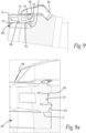
- the insert seat 27 furthermore comprises a side surface 32.
- the side surface 32 comprises two protruding wedge elements 35, which each extends along the associated side of the imaginary triangle 10 of the turning insert mounted in the insert seat 27. Therein, each wedge element 35 protrudes the most from the side surface 32 by an end surface at an end closest to a corner side surface 4 of mounted the turning insert. Between the two wedge elements 35, at the midpoint, the side surface 32 comprises a relief bulge 36.
- Each wedge element 35 comprises an inclined surface 37, which extends from the end surface and which, at an end closest to a midpoint half way between the corner side surfaces 4 of the mounted turning insert, runs out into the side surface 32 at an intersection thereof with the relief bulge 36.
- the side surface 32 includes primary support surfaces 33 in form of two separate part-surfaces.
- Each wedge element 35 is surrounded by a respective one of the two part-surfaces on three sides, and the relief bulge on the fourth side.
- Both part-surfaces are planar, and, as can be seen in Fig. 8 , form an angle ⁇ of 165° between them. In the example embodiment, the angle ⁇ is equal to the angle ⁇ formed by the part-surfaces of the turning insert.
- the side surface 32 comprises in total one pair of secondary support surfaces 34.
- the two secondary support surfaces 34 are located on an end surface of a respective one of the of the wedge elements 35, so that they extend outward relative a respective part-surface. Both secondary support surfaces 34 are planar, and face in opposite directions and face away from each other.
- each of the secondary support surfaces 34 form an angle ⁇ with the associated side of the imaginary triangle 10 of 90°.
- the angle ⁇ is equal to the angle ⁇ of the secondary support surfaces 21 of the turning insert.
- a normal to the plane of each secondary support surface 34 is parallel to the associated side of the imaginary triangle 10.
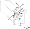
- a clamping mechanism comprises a spring element 38, a clamp 39 and a tightening screw 40.
- a first embodiment of a turning tool comprising the turning tool body 26 according to the first embodiment, the turning insert according to the first embodiment, and the clamping mechanism, is shown in Figs. 6 - 9 , wherein the turning insert is removably secured in the insert seat 27 of the turning tool body 27 by means of the clamping mechanism.
- the main seat support surface 29 of the insert seat 27 faces the main bottom support surface 15 of the turning insert.
- the part-surfaces constituting the primary support surfaces 33 of the insert seat 27 face a respective one of the part-surfaces constituting the primary support surfaces 13 of the at least one of the three main side surfaces 5 of the turning insert.
- the pair of secondary support surfaces 34 of the turning tool body pair face a respective one of the secondary support surfaces 21 of the pair of the at least one main side surface 5 of the turning insert.
- the tightening screw 40 of the clamping mechanism is tightened, whereby the clamp 39 engages the main top support surface 14 and presses the turning insert toward the shim 28 and toward the side surface 32.
- a corner cutting edge 6 is presented at the top surface 1.
- the corner cutting edge 6 may be used for cutting a rotating metal workpiece, wherein the corner cutting edge 6 may be fed in both directions across the bisector 9.
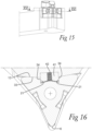
- the turning insert according to the second embodiment is also a double sided, negative turning insert for metal cutting, and has the same symmetry as the turning insert of the first embodiment, so that in the following, one of the main side surfaces 5 will be described, the other main side surfaces 5 comprise the same features.
- the depth of the recess 20 is defined by a bottom in form of a base surface 25.
- the depth of the single recess 20 decreases from each end wall in a direction along the associated side of the imaginary triangle 10 to a midpoint half way between the first and the second associated corner side surfaces 4.
- the base surface 25 extends outward from the primary support surfaces13, toward a most shallow point at the midpoint.
- the relief notch 19 is split in two by the single recess 20.
Landscapes
- Engineering & Computer Science (AREA)
- Mechanical Engineering (AREA)
- Cutting Tools, Boring Holders, And Turrets (AREA)
- Milling Processes (AREA)
Priority Applications (5)
| Application Number | Priority Date | Filing Date | Title |
|---|---|---|---|
| EP22217209.0A EP4393620A1 (fr) | 2022-12-29 | 2022-12-29 | Insert tournant |
| PCT/EP2023/077428 WO2024141192A1 (fr) | 2022-12-29 | 2023-10-04 | Insert rotatif |
| JP2025537575A JP2026503227A (ja) | 2022-12-29 | 2023-10-04 | 旋削インサート |
| KR1020257020168A KR20250129638A (ko) | 2022-12-29 | 2023-10-04 | 선삭 인서트 |
| CN202380082353.8A CN120225297A (zh) | 2022-12-29 | 2023-10-04 | 车削刀片 |
Applications Claiming Priority (1)
| Application Number | Priority Date | Filing Date | Title |
|---|---|---|---|
| EP22217209.0A EP4393620A1 (fr) | 2022-12-29 | 2022-12-29 | Insert tournant |
Publications (1)
| Publication Number | Publication Date |
|---|---|
| EP4393620A1 true EP4393620A1 (fr) | 2024-07-03 |
Family
ID=84689126
Family Applications (1)
| Application Number | Title | Priority Date | Filing Date |
|---|---|---|---|
| EP22217209.0A Pending EP4393620A1 (fr) | 2022-12-29 | 2022-12-29 | Insert tournant |
Country Status (5)
| Country | Link |
|---|---|
| EP (1) | EP4393620A1 (fr) |
| JP (1) | JP2026503227A (fr) |
| KR (1) | KR20250129638A (fr) |
| CN (1) | CN120225297A (fr) |
| WO (1) | WO2024141192A1 (fr) |
Citations (4)
| Publication number | Priority date | Publication date | Assignee | Title |
|---|---|---|---|---|
| US4050127A (en) * | 1975-11-21 | 1977-09-27 | Schwarzkopf Development Corporation | Clamping tool holder |
| WO2004071695A1 (fr) * | 2003-02-14 | 2004-08-26 | Sumitomo Electric Industries, Ltd. | Pointe de remplacement de bord et outil de coupe utilisant cette pointe |
| US20100329800A1 (en) * | 2009-06-24 | 2010-12-30 | Sandvik Intellectual Property Ab | Tool for chip removing machining as well as a solid indexable cutting insert and a solid basic body therefor |
| EP3153260B1 (fr) | 2015-10-09 | 2018-05-23 | Sandvik Intellectual Property AB | Insert de tournage et procede |
-
2022
- 2022-12-29 EP EP22217209.0A patent/EP4393620A1/fr active Pending
-
2023
- 2023-10-04 WO PCT/EP2023/077428 patent/WO2024141192A1/fr not_active Ceased
- 2023-10-04 CN CN202380082353.8A patent/CN120225297A/zh active Pending
- 2023-10-04 JP JP2025537575A patent/JP2026503227A/ja active Pending
- 2023-10-04 KR KR1020257020168A patent/KR20250129638A/ko active Pending
Patent Citations (4)
| Publication number | Priority date | Publication date | Assignee | Title |
|---|---|---|---|---|
| US4050127A (en) * | 1975-11-21 | 1977-09-27 | Schwarzkopf Development Corporation | Clamping tool holder |
| WO2004071695A1 (fr) * | 2003-02-14 | 2004-08-26 | Sumitomo Electric Industries, Ltd. | Pointe de remplacement de bord et outil de coupe utilisant cette pointe |
| US20100329800A1 (en) * | 2009-06-24 | 2010-12-30 | Sandvik Intellectual Property Ab | Tool for chip removing machining as well as a solid indexable cutting insert and a solid basic body therefor |
| EP3153260B1 (fr) | 2015-10-09 | 2018-05-23 | Sandvik Intellectual Property AB | Insert de tournage et procede |
Also Published As
| Publication number | Publication date |
|---|---|
| CN120225297A (zh) | 2025-06-27 |
| JP2026503227A (ja) | 2026-01-28 |
| WO2024141192A1 (fr) | 2024-07-04 |
| KR20250129638A (ko) | 2025-08-29 |
Similar Documents
| Publication | Publication Date | Title |
|---|---|---|
| EP1401603B1 (fr) | Plaquette de coupe frittee presentant un orifice central destine a une vis de serrage | |
| EP1539413B1 (fr) | Plaquette de decoupe et procede associe | |
| RU2338630C2 (ru) | Режущий инструмент и способ изготовления его державки | |
| US8066454B2 (en) | Milling tool with cooperating projections and recesses between the cutting insert and the holder | |
| US5957629A (en) | Fine milling cutting insert | |
| EP1480774B1 (fr) | Outil de coupe tangentiel et support dudit outil | |
| CN1117646C (zh) | 用于端面铣刀的可转位刀片 | |
| US6217263B1 (en) | Indexable insert for copy turning having a cutting corner formed by curved segments | |
| EP1297922B1 (fr) | Plaquette de coupe | |
| EP1899100B1 (fr) | Insert de coupe | |
| EP0925137B1 (fr) | Plaquette de coupe amovible | |
| EP1297921B1 (fr) | Plaquette de tournage | |
| EP0232692B1 (fr) | Plaquette de coupe indexable | |
| US6802676B2 (en) | Milling insert | |
| US20080304928A1 (en) | Tool for chip removing machining as well as a basic body and an indexable cutting insert therefor | |
| KR100465953B1 (ko) | 절삭 삽입체 | |
| US7309193B2 (en) | Indexable insert with corners with different radii | |
| US20200230715A1 (en) | Milling insert and a side and face milling tool | |
| JPWO2016093275A1 (ja) | 切削インサート、工具ボデーおよび切削工具 | |
| EP4393620A1 (fr) | Insert tournant | |
| US12240044B2 (en) | Turning insert for metal cutting | |
| EP4129546A1 (fr) | Plaquette de coupe et outil de coupe à pointe de coupe remplaçable | |
| EP4275821A1 (fr) | Insert de tournage, corps d'outil de tournage et outil de tournage de découpe de pièces métalliques | |
| JP2001219314A (ja) | スローアウェイチップ |
Legal Events
| Date | Code | Title | Description |
|---|---|---|---|
| PUAI | Public reference made under article 153(3) epc to a published international application that has entered the european phase |
Free format text: ORIGINAL CODE: 0009012 |
|
| STAA | Information on the status of an ep patent application or granted ep patent |
Free format text: STATUS: THE APPLICATION HAS BEEN PUBLISHED |
|
| AK | Designated contracting states |
Kind code of ref document: A1 Designated state(s): AL AT BE BG CH CY CZ DE DK EE ES FI FR GB GR HR HU IE IS IT LI LT LU LV MC ME MK MT NL NO PL PT RO RS SE SI SK SM TR |
|
| STAA | Information on the status of an ep patent application or granted ep patent |
Free format text: STATUS: REQUEST FOR EXAMINATION WAS MADE |
|
| 17P | Request for examination filed |
Effective date: 20250103 |