EP4393665A1 - Schneidvorrichtung - Google Patents
Schneidvorrichtung Download PDFInfo
- Publication number
- EP4393665A1 EP4393665A1 EP23220290.3A EP23220290A EP4393665A1 EP 4393665 A1 EP4393665 A1 EP 4393665A1 EP 23220290 A EP23220290 A EP 23220290A EP 4393665 A1 EP4393665 A1 EP 4393665A1
- Authority
- EP
- European Patent Office
- Prior art keywords
- state
- cutting blades
- detection unit
- pair
- unit
- Prior art date
- Legal status (The legal status is an assumption and is not a legal conclusion. Google has not performed a legal analysis and makes no representation as to the accuracy of the status listed.)
- Pending
Links
Images




Classifications
-
- B—PERFORMING OPERATIONS; TRANSPORTING
- B23—MACHINE TOOLS; METAL-WORKING NOT OTHERWISE PROVIDED FOR
- B23D—PLANING; SLOTTING; SHEARING; BROACHING; SAWING; FILING; SCRAPING; LIKE OPERATIONS FOR WORKING METAL BY REMOVING MATERIAL, NOT OTHERWISE PROVIDED FOR
- B23D29/00—Hand-held metal-shearing or metal-cutting devices
- B23D29/002—Hand-held metal-shearing or metal-cutting devices for cutting wire or the like
-
- B—PERFORMING OPERATIONS; TRANSPORTING
- B26—HAND CUTTING TOOLS; CUTTING; SEVERING
- B26B—HAND-HELD CUTTING TOOLS NOT OTHERWISE PROVIDED FOR
- B26B15/00—Hand-held shears with motor-driven blades
-
- B—PERFORMING OPERATIONS; TRANSPORTING
- B23—MACHINE TOOLS; METAL-WORKING NOT OTHERWISE PROVIDED FOR
- B23D—PLANING; SLOTTING; SHEARING; BROACHING; SAWING; FILING; SCRAPING; LIKE OPERATIONS FOR WORKING METAL BY REMOVING MATERIAL, NOT OTHERWISE PROVIDED FOR
- B23D33/00—Accessories for shearing machines or shearing devices
- B23D33/02—Arrangements for holding, guiding, and/or feeding work during the operation
-
- B—PERFORMING OPERATIONS; TRANSPORTING
- B26—HAND CUTTING TOOLS; CUTTING; SEVERING
- B26B—HAND-HELD CUTTING TOOLS NOT OTHERWISE PROVIDED FOR
- B26B29/00—Guards or sheaths or guides for hand cutting tools; Arrangements for guiding hand cutting tools
- B26B29/04—Guards or sheaths for scissors, e.g. combined with manicuring appliances
-
- B—PERFORMING OPERATIONS; TRANSPORTING
- B26—HAND CUTTING TOOLS; CUTTING; SEVERING
- B26B—HAND-HELD CUTTING TOOLS NOT OTHERWISE PROVIDED FOR
- B26B29/00—Guards or sheaths or guides for hand cutting tools; Arrangements for guiding hand cutting tools
- B26B29/06—Arrangements for guiding hand cutting tools
-
- B—PERFORMING OPERATIONS; TRANSPORTING
- B26—HAND CUTTING TOOLS; CUTTING; SEVERING
- B26D—CUTTING; DETAILS COMMON TO MACHINES FOR PERFORATING, PUNCHING, CUTTING-OUT, STAMPING-OUT OR SEVERING
- B26D3/00—Cutting work characterised by the nature of the cut made; Apparatus therefor
- B26D3/16—Cutting rods or tubes transversely
- B26D3/169—Hand held tube cutters
-
- B—PERFORMING OPERATIONS; TRANSPORTING
- B26—HAND CUTTING TOOLS; CUTTING; SEVERING
- B26D—CUTTING; DETAILS COMMON TO MACHINES FOR PERFORATING, PUNCHING, CUTTING-OUT, STAMPING-OUT OR SEVERING
- B26D5/00—Arrangements for operating and controlling machines or devices for cutting, cutting-out, stamping-out, punching, perforating, or severing by means other than cutting
- B26D5/08—Means for actuating the cutting member to effect the cut
- B26D5/086—Electric, magnetic, piezoelectric, electro-magnetic means
-
- B—PERFORMING OPERATIONS; TRANSPORTING
- B26—HAND CUTTING TOOLS; CUTTING; SEVERING
- B26D—CUTTING; DETAILS COMMON TO MACHINES FOR PERFORATING, PUNCHING, CUTTING-OUT, STAMPING-OUT OR SEVERING
- B26D5/00—Arrangements for operating and controlling machines or devices for cutting, cutting-out, stamping-out, punching, perforating, or severing by means other than cutting
- B26D5/20—Arrangements for operating and controlling machines or devices for cutting, cutting-out, stamping-out, punching, perforating, or severing by means other than cutting with interrelated action between the cutting member and work feed
- B26D5/26—Arrangements for operating and controlling machines or devices for cutting, cutting-out, stamping-out, punching, perforating, or severing by means other than cutting with interrelated action between the cutting member and work feed wherein control means on the work feed means renders the cutting member operative
- B26D5/28—Arrangements for operating and controlling machines or devices for cutting, cutting-out, stamping-out, punching, perforating, or severing by means other than cutting with interrelated action between the cutting member and work feed wherein control means on the work feed means renders the cutting member operative the control means being responsive to presence or absence of work
-
- B—PERFORMING OPERATIONS; TRANSPORTING
- B23—MACHINE TOOLS; METAL-WORKING NOT OTHERWISE PROVIDED FOR
- B23D—PLANING; SLOTTING; SHEARING; BROACHING; SAWING; FILING; SCRAPING; LIKE OPERATIONS FOR WORKING METAL BY REMOVING MATERIAL, NOT OTHERWISE PROVIDED FOR
- B23D17/00—Shearing machines or shearing devices cutting by blades pivoted on a single axis
- B23D17/02—Shearing machines or shearing devices cutting by blades pivoted on a single axis characterised by drives or gearings therefor
- B23D17/04—Shearing machines or shearing devices cutting by blades pivoted on a single axis characterised by drives or gearings therefor actuated by a rotary shaft
Definitions
- the present disclosure relates to an electric cutting device.
- an electric pruning shear and the like as described in JP2021-40594A are known, for example.
- cutting blades are operated by a driving force of an electric motor instead of a gripping force of a user, and cut an object to be cut by clamping the object with the pair of cutting blades.
- the above electric pruning shear is one in which a tree branch is set as an object to be cut, but a cutting device in which metal such as a reinforcing bar is set as the object to be cut is also known.
- a cutting device is often provided with a trigger switch or the like that is operated by a finger of a user, for example, as a switch for starting an operation of a cutting blade.
- a trigger switch or the like that is operated by a finger of a user, for example, as a switch for starting an operation of a cutting blade.
- Illustrative aspects of the present disclosure provide a cutting device that does not start cutting an object to be cut when a positional relationship between a cutting blade and the object to be cut is inappropriate.
- An electric cutting device includes: a pair of cutting blades configured to clamp and cut an object; an electric motor configured to generate a driving force necessary for operating the cutting blades; a control unit configured to control an operation of the electric motor; an operation unit configured to be switched between an ON state and an OFF state by a user operation; and a detection unit configured to: enter into an ON state in a case where the object is present between the pair of cutting blades; and enter into an OFF state in a case where the object is not present.
- the control unit is configured to execute an operation of closing the pair of cutting blades in a case where both the operation unit and the detection unit are in the ON state.
- the operation unit operated by the user is provided separately from the detection unit that is configured to enter into an ON state in the case where the object is present between the pair of cutting blades and to enter into an OFF state in the case where the object is not present.
- the control unit executes an operation of closing the pair of cutting blades in the case where both the operation unit and the detection unit are in the ON state.
- a cutting device that does not start cutting an object when a positional relationship between a cutting blade and the object is inappropriate is provided.
- a cutting device 10 is an electric cutting device, and is configured as a device for cutting a reinforcing bar at a construction site or the like.
- a configuration of the cutting device 10 will be described mainly with reference to FIG. 1 .
- the cutting device 10 includes a housing 11, a trigger switch 12, a cutting mechanism 100, a ball screw 200, a speed reducer 300, an electric motor 400, a control board 500, and a storage battery 600.
- the cutting device 10 also includes a detection unit 800 (see FIG. 3 ), but showing thereof is omitted in FIG. 1 .
- the housing 11 is a container that defines an outer shape of the cutting device 10.
- the housing 11 is made of resin, for example.
- the ball screw 200 described later, the speed reducer 300 described later, and the like are housed inside the housing 11.
- FIG. 1 a portion of the housing 11 on a front side when viewed on paper is removed, and an internal configuration of the cutting device 10 is shown as a cross-sectional view.
- the trigger switch 12 is a switch operated by a finger of a user.
- the user can turn on the trigger switch 12 by placing his or her finger on the trigger switch 12 and pulling the trigger switch 12 to the front side.
- the trigger switch 12 returns to an original position due to a force of a spring, and enters into the OFF state.
- a corresponding signal is transmitted to the control board 500 described later.
- the trigger switch 12 corresponds to an "operation unit" that can be switched between the ON state and the OFF state by an operation performed by the user. As will be described later, the user turns on the trigger switch 12 as one of the operations necessary to start cutting the reinforcing bar.
- the cutting mechanism 100 is a portion configured to cut the reinforcing bar which is an object to be cut.
- the cutting mechanism 100 includes a pair of blade members 110 and a pair of link members 120.
- the cutting blades 111 configured to clamp and cut the object to be cut are formed on the respective blade members 110.
- the blade member 110 is held pivotably about a shaft 101 fixed to the housing 11.
- the respective blade members 110 are arranged to face each other such that ridge lines of blade edges of the cutting blades 111 operate on trajectories passing through substantially the same plane. Accordingly, it is possible to switch between an opened state where the respective cutting blades 111 are spaced apart from each other and a closed state where the respective cutting blades 111 come into contact with (or close to) each other. In the example of FIG. 1 , the pair of cutting blades 111 are in the closed state.
- Each link member 120 is a rod-shaped member, and one end of the link member 120 is connected to the blade member 110 via a shaft 102, and the other end of the link member 120 is connected to a connection member 230 described later via a shaft 231.
- the link member 120 and the blade member 110 are connected to each other in a manner of pivoting about the shaft 102.
- the link member 120 and the connection member 230 are connected to each other in a manner of pivoting about the shaft 231.
- the connection member 230 moves in a left-right direction in FIG. 1 by a driving force of the electric motor 400.
- connection member 230 moves in a left direction from the state shown in FIG. 1 , the blade member 110 on an upper side of FIG. 1 pivots counterclockwise, and the blade member 110 on a lower side of FIG. 1 pivots clockwise. Accordingly, the pair of cutting blades 111 change from the closed state to the opened state.
- the pair of cutting blades 111 are in the opened state, if the connection member 230 moves in the right direction in FIG. 1 , the blade member 110 on the upper side of FIG. 1 pivots clockwise, and the blade member 110 on the lower side of FIG. 1 pivots counterclockwise. Accordingly, the pair of cutting blades 111 return to the closed state. Accordingly, the pair of blade members 110, the pair of link members 120, and the connection member 230 as a whole configure a so-called "toggle link mechanism".
- a pair of guide plates 700 are provided near the blade members 110.
- the guide plates 700 are plate-shaped members made of metal, and are disposed to sandwich the blade members 110 from both the front side and the back side in FIG. 1 when viewed on paper. Shapes of the pair of guide plates 700 are substantially the same. As shown in FIG. 2 , each guide plate 700 has a recess 710 formed therein.
- each recess 710 is formed to recede from the front end side toward the rear end side of the guide plate 700.
- each recess 710 is formed at a position that includes the cutting blade 111 in the closed state. In the standby state where the cutting blades 111 are fully opened, the cutting blades 111 are retracted to the outside of the recesses 710, and from a perspective of FIG. 2 , the entire blade members 110 are hidden by the guide plates 700.
- the guide plates 700 have both a function of covering and protecting the cutting blades 111 in the standby state, and a function of guiding the reinforcing bar, which is the object to be cut, along the recesses 710 between the pair of cutting blades 111.
- the guide plates 700 further have a function of stabilizing a posture of the cutting device 10 before and after cutting by sandwiching the reinforcing bar in the recesses 710.
- the screw shaft 210 is a rod-shaped member that extends linearly from the rear end side to the front end side.
- a male screw is formed on an outer peripheral surface of the screw shaft 210.
- the nut 220 is a substantially cylindrical member disposed to surround the screw shaft 210 from an outer peripheral side.
- a female screw is formed on an inner peripheral surface of the nut 220, and is screwed to the male screw formed on the outer peripheral surface of the screw shaft 210. While the nut 220 is allowed to move along a longitudinal direction of the screw shaft 210, rotation about the central axis of the screw shaft 210 is restricted. Therefore, when the screw shaft 210 rotates about the central axis thereof, the nut 220 moves in the left-right direction in FIG. 1 along the central axis.
- connection member 230 is a member attached to the nut 220 and is a member that moves along the screw shaft 210 together with the nut 220.
- the connection member 230 is attached in a manner of protruding from the nut 220 toward the front end side.
- the pair of link members 120 are connected to a portion of the connection member 230 near an end on the front end side via the shaft 231 described above.
- a magnet 241 is attached to the outer peripheral surface of the connection member 230.
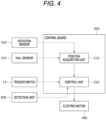
- a Hall sensor 242 is attached to the housing 11 at a position near the connection member 230. The position where the Hall sensor 242 is attached is such that when the nut 220 moves to a rear end from the state shown in FIG. 1 and the cutting blades 111 are fully opened, the Hall sensor 242 faces the magnet 241 of the connection member 230. When the cutting blades 111 are fully opened, a signal is transmitted from the Hall sensor 242 by facing the magnet 241, and the signal is input to the control board 500.
- the speed reducer 300 is a device that is configured to reduce a rotation speed of an output shaft 410 of the electric motor 400 and then transmit the rotation to the screw shaft 210 of the ball screw 200.
- the storage battery 600 stores electric power necessary for operating the electric motor 400 and the control board 500, and is, for example, a lithium ion battery.
- a configuration may be adopted in which the storage battery 600 can be charged while the storage battery 600 is attached to the housing 11.
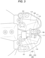
- the detection unit 800 is provided at a position near the cutting blades 111.
- the detection unit 800 is a switch for detecting the object to be cut.
- the detection unit 800 is configured to enter into an ON state if a reinforcing bar RB is present at a predetermined position between the pair of cutting blades 111, and to enter into an OFF state if the reinforcing bar RB is not present.
- the detection unit 800 includes an actuating unit 810 and a switch 820.
- the second portion 812 is in a position overlapping a part of each recess 710 in a side view. Specifically, the second portion 812 overlaps a portion of each recess 710 near the rear end side.
- the position of the actuating unit 810 shown in FIG. 3 is a position closest to the front end side within a movable range thereof.
- the reinforcing bar RB moves relatively to a back side of the recess 710. That is, the reinforcing bar RB comes into contact with the second portion 812 on the way, and thereafter moves to the back side (rear end side) together with the actuating unit 810.
- the reinforcing bar RB moves to an innermost position of each recess 710.
- the actuating unit 810 At a time point when the reinforcing bar RB reaches the back side of the recess 710, the actuating unit 810 is at the rearmost position within the movable range thereof. In this way, the actuating unit 810 comes into contact with the reinforcing bar RB inserted between the pair of cutting blades 111, and operates in response to a force from the reinforcing bar RB.
- the switch 820 is a portion that is configured to convert the actuation of the actuating unit 810 into an electrical signal.
- the switch 820 is held by, for example, the guide plates 700 at a position on the rear end side of the actuating unit 810.
- the switch 820 includes a movable portion 821.
- the movable portion 821 protrudes from a main body portion toward a front end side of the switch 820, and a front end of the movable portion 821 abuts an end portion on the rear end side of the first portion 811.
- the movable portion 821 is urged toward the front end side by a spring (not shown).
- the switch 820 of the detection unit 800 is in the OFF state.
- the switch 820 changes from the OFF state to the ON state. Then, when cutting of the reinforcing bar RB is completed and the reinforcing bar RB is not present in the recess 710, the switch 820 returns to the OFF state.
- the control board 500 starts the operation of the cutting blades 111 only when both the trigger switch 12 (operation unit) and the detection unit 800 are turned on.
- the detection unit 800 is implemented by a "contact switch" that is configured to detect the presence or absence of the reinforcing bar RB by physically bringing the actuating unit 810 into contact with the reinforcing bar RB.
- the detection unit 800 may be implemented by a switch that is configured to detect the presence or absence of the reinforcing bar RB in a non-contact manner, for example, using an optical sensor.
- the control board 500 including the microcomputer includes a position acquisition unit 510 and a control unit 520 as elements representing functions of the control board 500.
- a reset operation may be performed when the cutting device 10 is started up.
- the electric motor 400 may be driven in a direction where the pair of cutting blades 111 change from the closed state to the opened state, and the electric motor 400 may be stopped at a time point when a detection signal from the Hall sensor 242 is input. By starting counting the pulse signals from this time point, the current position of the cutting blades 111 can be accurately acquired from then on.
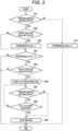
- step S02 it is determined by the control board 500, for example, whether the detection unit 800 is in the OFF state. If the detection unit 800 is in the OFF state, the processing proceeds to step S03. In step S03, the value of the permission flag is set to 1. Then, the processing proceeds to step S04. In step S02, if the detection unit 800 is in the ON state, the processing proceeds to step S04 without performing step S03.
- the permission flag in this modification is used as an internal variable to store that the detection unit 800 is turned on before the trigger switch 12 is turned on.
- the operation of the cutting blades 111 is started only when the detection unit 800 is first turned on and the trigger switch 12 is then turned on.
- the fourth portion 814 of the actuating unit 810 protrudes further toward the front end side than the front end of the guide plate 700.
- a protrusion amount is approximately equal to an operation stroke of the movable portion 821. If the cutting device 10 is not provided with the guide plates 700, the fourth portion 814 may be made to protrude from the front end of the cutting blade 111 by the above stroke.
- the fourth portion 814 comes into contact with the floor before the guide plate 700 does.
- the actuating unit 810 and the movable portion 821 are pushed in by a force from the floor FL, and the detection unit 800 is turned on.
Landscapes
- Engineering & Computer Science (AREA)
- Mechanical Engineering (AREA)
- Life Sciences & Earth Sciences (AREA)
- Forests & Forestry (AREA)
- Scissors And Nippers (AREA)
- Sawing (AREA)
- Shearing Machines (AREA)
- Milling Processes (AREA)
- Nonmetal Cutting Devices (AREA)
- Details Of Cutting Devices (AREA)
Applications Claiming Priority (8)
| Application Number | Priority Date | Filing Date | Title |
|---|---|---|---|
| JP2022210308A JP2024093744A (ja) | 2022-12-27 | 2022-12-27 | 切断装置 |
| JP2022210302A JP2024093739A (ja) | 2022-12-27 | 2022-12-27 | 切断装置 |
| JP2022210594A JP2024093934A (ja) | 2022-12-27 | 2022-12-27 | 切断装置 |
| JP2022210362A JP2024093782A (ja) | 2022-12-27 | 2022-12-27 | 切断装置 |
| JP2022210196A JP2024093671A (ja) | 2022-12-27 | 2022-12-27 | 切断装置 |
| JP2022210372A JP2024093790A (ja) | 2022-12-27 | 2022-12-27 | 切断装置 |
| JP2022210296A JP2024093736A (ja) | 2022-12-27 | 2022-12-27 | 切断装置 |
| JP2022210638 | 2022-12-27 |
Publications (1)
| Publication Number | Publication Date |
|---|---|
| EP4393665A1 true EP4393665A1 (de) | 2024-07-03 |
Family
ID=89385883
Family Applications (7)
| Application Number | Title | Priority Date | Filing Date |
|---|---|---|---|
| EP23220293.7A Pending EP4403321A1 (de) | 2022-12-27 | 2023-12-27 | Schneidvorrichtung |
| EP23220289.5A Pending EP4397458A1 (de) | 2022-12-27 | 2023-12-27 | Schneidvorrichtung |
| EP23220295.2A Pending EP4393666A1 (de) | 2022-12-27 | 2023-12-27 | Schneidvorrichtung |
| EP23220271.3A Pending EP4393663A1 (de) | 2022-12-27 | 2023-12-27 | Schneidvorrichtung |
| EP23220287.9A Pending EP4393664A1 (de) | 2022-12-27 | 2023-12-27 | Schneidvorrichtung |
| EP23220296.0A Pending EP4403322A3 (de) | 2022-12-27 | 2023-12-27 | Schneidvorrichtung |
| EP23220290.3A Pending EP4393665A1 (de) | 2022-12-27 | 2023-12-27 | Schneidvorrichtung |
Family Applications Before (6)
| Application Number | Title | Priority Date | Filing Date |
|---|---|---|---|
| EP23220293.7A Pending EP4403321A1 (de) | 2022-12-27 | 2023-12-27 | Schneidvorrichtung |
| EP23220289.5A Pending EP4397458A1 (de) | 2022-12-27 | 2023-12-27 | Schneidvorrichtung |
| EP23220295.2A Pending EP4393666A1 (de) | 2022-12-27 | 2023-12-27 | Schneidvorrichtung |
| EP23220271.3A Pending EP4393663A1 (de) | 2022-12-27 | 2023-12-27 | Schneidvorrichtung |
| EP23220287.9A Pending EP4393664A1 (de) | 2022-12-27 | 2023-12-27 | Schneidvorrichtung |
| EP23220296.0A Pending EP4403322A3 (de) | 2022-12-27 | 2023-12-27 | Schneidvorrichtung |
Country Status (6)
| Country | Link |
|---|---|
| US (7) | US20240208088A1 (de) |
| EP (7) | EP4403321A1 (de) |
| KR (4) | KR20240104041A (de) |
| AU (4) | AU2023285962A1 (de) |
| CA (4) | CA3224768A1 (de) |
| TW (4) | TW202435744A (de) |
Families Citing this family (2)
| Publication number | Priority date | Publication date | Assignee | Title |
|---|---|---|---|---|
| US20240300038A1 (en) * | 2023-03-09 | 2024-09-12 | Milwaukee Electric Tool Corporation | Powered tubing cutter |
| KR20260020745A (ko) | 2024-08-05 | 2026-02-12 | 주식회사 엘지에너지솔루션 | 배터리 팩 |
Citations (5)
| Publication number | Priority date | Publication date | Assignee | Title |
|---|---|---|---|---|
| EP1452280A1 (de) * | 2001-10-25 | 2004-09-01 | Hispaes, S.A. | Motorisiertes schneidwerkzeug mit einer automatisierten schneidvorrichtung |
| EP3466578A1 (de) * | 2016-05-24 | 2019-04-10 | Izumi Products Company | Elektrowerkzeug |
| US10799962B2 (en) * | 2016-12-09 | 2020-10-13 | Cembre S.P.A. | Working head for a compression or cutting tool |
| JP2021040594A (ja) | 2019-09-13 | 2021-03-18 | アルスコーポレーション株式会社 | 剪定用電動切断装置 |
| US20210339410A1 (en) * | 2020-04-30 | 2021-11-04 | Max Co., Ltd. | Electric scissors |
Family Cites Families (19)
| Publication number | Priority date | Publication date | Assignee | Title |
|---|---|---|---|---|
| US2529895A (en) * | 1948-05-06 | 1950-11-14 | George V Anderson | Electrical cutting and punching machine |
| US3688405A (en) * | 1971-04-21 | 1972-09-05 | Joseph G Dutra Jr | Pruning shears |
| US4369576A (en) * | 1981-05-22 | 1983-01-25 | Mcvaugh Arthur K | Hand-held cable cutter |
| US5235750A (en) * | 1992-05-19 | 1993-08-17 | Brown Frank R | Hand tools |
| US6735870B2 (en) * | 2001-01-09 | 2004-05-18 | Greenlee Textron Inc. | Cutter for fiber optic cable and method of using same |
| JP2004305690A (ja) * | 2003-02-18 | 2004-11-04 | Hasegawa Hamono Kk | 鋏用キャップ及び鋏 |
| ES2245217B1 (es) * | 2004-03-04 | 2006-08-01 | Josep Gurri Molins | Util de corte portatil accionado mecanicamente. |
| ES2268954B1 (es) * | 2005-01-27 | 2008-03-01 | Josep Gurri Molins | Util de corte motorizado portatil. |
| EP2158803B1 (de) * | 2008-08-26 | 2011-04-27 | Robert Bosch GmbH | Gemüseschneidewerkzeug |
| US8327548B2 (en) * | 2009-02-23 | 2012-12-11 | Ronan John S | Utility cutter with a non-tool blade changer |
| CN201493868U (zh) | 2009-09-08 | 2010-06-02 | 南京德朔实业有限公司 | 电动剪刀 |
| FR2957834B1 (fr) | 2010-03-24 | 2012-03-09 | Infaco | Dispositif de controle positionnel de deux elements l'un par rapport a l'autre tel que lames d'outils de coupe du genre secateur et outil de coupe le comportant |
| US9888632B2 (en) | 2010-12-30 | 2018-02-13 | Techtronic Outdoor Products Technology Limited | Powered cutting tool |
| JP5741252B2 (ja) * | 2011-06-28 | 2015-07-01 | マックス株式会社 | 電動はさみ |
| BR112015000538A2 (pt) | 2012-07-10 | 2017-06-27 | Klauke Gmbh Gustav | ferramenta de pressão |
| US11292118B2 (en) * | 2018-01-30 | 2022-04-05 | Milwaukee Electric Tool Corporation | Power tool |
| FI128867B (en) * | 2019-08-29 | 2021-02-15 | Tmi Linden Instr | ELECTRIC ARM CUTTER |
| US12202155B2 (en) * | 2020-09-10 | 2025-01-21 | Techtronic Cordless Gp | Blade change mechanism for power tool |
| KR20240032642A (ko) * | 2022-09-03 | 2024-03-12 | 둥관 코햄 인더스트리얼 컴퍼니 리미티드 | 소자의 인덕턴스 특성에 기반한 신호 생성부재, 전동 전단공구 및 전동 전단공구의 전단 개방도 제어방법 |
-
2023
- 2023-12-21 CA CA3224768A patent/CA3224768A1/en active Pending
- 2023-12-22 AU AU2023285962A patent/AU2023285962A1/en active Pending
- 2023-12-22 CA CA3224822A patent/CA3224822A1/en active Pending
- 2023-12-22 CA CA3224805A patent/CA3224805A1/en active Pending
- 2023-12-22 AU AU2023285960A patent/AU2023285960A1/en active Pending
- 2023-12-22 AU AU2023285963A patent/AU2023285963A1/en active Pending
- 2023-12-22 CA CA3224813A patent/CA3224813A1/en active Pending
- 2023-12-22 AU AU2023285964A patent/AU2023285964A1/en active Pending
- 2023-12-26 KR KR1020230191441A patent/KR20240104041A/ko active Pending
- 2023-12-26 TW TW112150787A patent/TW202435744A/zh unknown
- 2023-12-26 KR KR1020230191431A patent/KR20240104040A/ko active Pending
- 2023-12-26 TW TW112150784A patent/TW202440253A/zh unknown
- 2023-12-26 KR KR1020230191411A patent/KR20240104036A/ko active Pending
- 2023-12-26 TW TW112150783A patent/TW202435743A/zh unknown
- 2023-12-26 KR KR1020230191421A patent/KR20240104038A/ko active Pending
- 2023-12-26 TW TW112150785A patent/TW202440254A/zh unknown
- 2023-12-27 EP EP23220293.7A patent/EP4403321A1/de active Pending
- 2023-12-27 EP EP23220289.5A patent/EP4397458A1/de active Pending
- 2023-12-27 US US18/397,582 patent/US20240208088A1/en active Pending
- 2023-12-27 EP EP23220295.2A patent/EP4393666A1/de active Pending
- 2023-12-27 US US18/397,763 patent/US20240208090A1/en active Pending
- 2023-12-27 EP EP23220271.3A patent/EP4393663A1/de active Pending
- 2023-12-27 EP EP23220287.9A patent/EP4393664A1/de active Pending
- 2023-12-27 US US18/397,796 patent/US12576546B2/en active Active
- 2023-12-27 EP EP23220296.0A patent/EP4403322A3/de active Pending
- 2023-12-27 US US18/397,502 patent/US20240207953A1/en active Pending
- 2023-12-27 US US18/397,608 patent/US12570014B2/en active Active
- 2023-12-27 US US18/397,697 patent/US12583135B2/en active Active
- 2023-12-27 EP EP23220290.3A patent/EP4393665A1/de active Pending
- 2023-12-27 US US18/397,730 patent/US12544942B2/en active Active
Patent Citations (5)
| Publication number | Priority date | Publication date | Assignee | Title |
|---|---|---|---|---|
| EP1452280A1 (de) * | 2001-10-25 | 2004-09-01 | Hispaes, S.A. | Motorisiertes schneidwerkzeug mit einer automatisierten schneidvorrichtung |
| EP3466578A1 (de) * | 2016-05-24 | 2019-04-10 | Izumi Products Company | Elektrowerkzeug |
| US10799962B2 (en) * | 2016-12-09 | 2020-10-13 | Cembre S.P.A. | Working head for a compression or cutting tool |
| JP2021040594A (ja) | 2019-09-13 | 2021-03-18 | アルスコーポレーション株式会社 | 剪定用電動切断装置 |
| US20210339410A1 (en) * | 2020-04-30 | 2021-11-04 | Max Co., Ltd. | Electric scissors |
Also Published As
Similar Documents
| Publication | Publication Date | Title |
|---|---|---|
| EP4393665A1 (de) | Schneidvorrichtung | |
| US10427284B2 (en) | Fastener driving tool | |
| JP2024093934A (ja) | 切断装置 | |
| CN118253666A (zh) | 切断装置 | |
| US12491647B2 (en) | Cutting device | |
| JP2024093782A (ja) | 切断装置 | |
| JP2024093739A (ja) | 切断装置 | |
| JP2024093790A (ja) | 切断装置 | |
| JP2024093671A (ja) | 切断装置 | |
| JP2024093744A (ja) | 切断装置 |
Legal Events
| Date | Code | Title | Description |
|---|---|---|---|
| PUAI | Public reference made under article 153(3) epc to a published international application that has entered the european phase |
Free format text: ORIGINAL CODE: 0009012 |
|
| STAA | Information on the status of an ep patent application or granted ep patent |
Free format text: STATUS: THE APPLICATION HAS BEEN PUBLISHED |
|
| AK | Designated contracting states |
Kind code of ref document: A1 Designated state(s): AL AT BE BG CH CY CZ DE DK EE ES FI FR GB GR HR HU IE IS IT LI LT LU LV MC ME MK MT NL NO PL PT RO RS SE SI SK SM TR |
|
| STAA | Information on the status of an ep patent application or granted ep patent |
Free format text: STATUS: REQUEST FOR EXAMINATION WAS MADE |
|
| 17P | Request for examination filed |
Effective date: 20241230 |