EP4393707A2 - Appareil dentaire amovible a renforcement interproximal - Google Patents
Appareil dentaire amovible a renforcement interproximal Download PDFInfo
- Publication number
- EP4393707A2 EP4393707A2 EP24173374.0A EP24173374A EP4393707A2 EP 4393707 A2 EP4393707 A2 EP 4393707A2 EP 24173374 A EP24173374 A EP 24173374A EP 4393707 A2 EP4393707 A2 EP 4393707A2
- Authority
- EP
- European Patent Office
- Prior art keywords
- tooth
- interproximal
- appliance
- removable dental
- appliance body
- Prior art date
- Legal status (The legal status is an assumption and is not a legal conclusion. Google has not performed a legal analysis and makes no representation as to the accuracy of the status listed.)
- Granted
Links
Images







Classifications
-
- A—HUMAN NECESSITIES
- A61—MEDICAL OR VETERINARY SCIENCE; HYGIENE
- A61C—DENTISTRY; APPARATUS OR METHODS FOR ORAL OR DENTAL HYGIENE
- A61C7/00—Orthodontics, i.e. obtaining or maintaining the desired position of teeth, e.g. by straightening, evening, regulating, separating, or by correcting malocclusions
- A61C7/08—Mouthpiece-type retainers or positioners, e.g. for both the lower and upper arch
-
- A—HUMAN NECESSITIES
- A61—MEDICAL OR VETERINARY SCIENCE; HYGIENE
- A61C—DENTISTRY; APPARATUS OR METHODS FOR ORAL OR DENTAL HYGIENE
- A61C7/00—Orthodontics, i.e. obtaining or maintaining the desired position of teeth, e.g. by straightening, evening, regulating, separating, or by correcting malocclusions
- A61C7/002—Orthodontic computer assisted systems
-
- A—HUMAN NECESSITIES
- A61—MEDICAL OR VETERINARY SCIENCE; HYGIENE
- A61C—DENTISTRY; APPARATUS OR METHODS FOR ORAL OR DENTAL HYGIENE
- A61C7/00—Orthodontics, i.e. obtaining or maintaining the desired position of teeth, e.g. by straightening, evening, regulating, separating, or by correcting malocclusions
- A61C7/12—Brackets; Arch wires; Combinations thereof; Accessories therefor
- A61C7/20—Arch wires
-
- A—HUMAN NECESSITIES
- A61—MEDICAL OR VETERINARY SCIENCE; HYGIENE
- A61C—DENTISTRY; APPARATUS OR METHODS FOR ORAL OR DENTAL HYGIENE
- A61C9/00—Impression cups, i.e. impression trays; Impression methods
- A61C9/004—Means or methods for taking digitized impressions
-
- B—PERFORMING OPERATIONS; TRANSPORTING
- B33—ADDITIVE MANUFACTURING TECHNOLOGY
- B33Y—ADDITIVE MANUFACTURING, i.e. MANUFACTURING OF THREE-DIMENSIONAL [3D] OBJECTS BY ADDITIVE DEPOSITION, ADDITIVE AGGLOMERATION OR ADDITIVE LAYERING, e.g. BY 3D PRINTING, STEREOLITHOGRAPHY OR SELECTIVE LASER SINTERING
- B33Y80/00—Products made by additive manufacturing
-
- A—HUMAN NECESSITIES
- A61—MEDICAL OR VETERINARY SCIENCE; HYGIENE
- A61C—DENTISTRY; APPARATUS OR METHODS FOR ORAL OR DENTAL HYGIENE
- A61C19/00—Dental auxiliary appliances
- A61C19/04—Measuring instruments specially adapted for dentistry
- A61C19/05—Measuring instruments specially adapted for dentistry for determining occlusion
-
- A—HUMAN NECESSITIES
- A61—MEDICAL OR VETERINARY SCIENCE; HYGIENE
- A61C—DENTISTRY; APPARATUS OR METHODS FOR ORAL OR DENTAL HYGIENE
- A61C5/00—Filling or capping teeth
- A61C5/90—Oral protectors for use during treatment, e.g. lip or mouth protectors
Definitions
- Orthodontic devices and treatment methods generally involve the application of forces to move teeth into a proper bite configuration, or occlusion.
- orthodontic treatment may involve the use of slotted appliances, known as brackets, which are fixed to the patient's anterior, cuspid, and bicuspid teeth.
- An archwire is typically placed in the slot of each bracket and serves as a track to guide movement of the teeth to desired orientations.
- the ends of the archwire are usually received in appliances known as buccal tubes that are secured to the patient's molar teeth.
- Such dental appliances remain in the mouth of the patient and are periodically adjusted by an orthodontist to check the process and maintain the proper force on the teeth until proper alignment is achieved.
- orthodontic treatment may require some tooth movements that are difficult for a CTA to achieve, such as, for example, tooth root movements and rotations of cuspids and bicuspids.
- tooth movements that are difficult for a CTA to achieve, such as, for example, tooth root movements and rotations of cuspids and bicuspids.
- the forces and moments that a CTA is capable of applying directly to the surfaces of a tooth may be insufficient to achieve the desired tooth movement.
- the disclosure describes a removable dental appliance including an appliance body configured to at least partially surround a plurality teeth of a dental arch of a patient; and an interproximal reinforcement.
- the appliance body includes a first shell shaped to engage a first tooth of the plurality of teeth in an initial position of the first tooth; and a second shell shaped to engage a second tooth of the plurality of teeth in an initial position of the second tooth.
- the second tooth is adjacent to the first tooth.
- the interproximal reinforcement extends from a first gingival edge of the appliance body on a labial side of the appliance body along an interproximal region between the first tooth and the second tooth to a second gingival edge of the appliance body on a lingual side of the appliance body.
- the interproximal reinforcement is configured to engage at least one of a lingual surface of the first tooth below a height of contour of the first tooth or a labial surface of the first tooth below the height of contour to enable the appliance body to apply a force vector at a contact point on the first tooth to cause movement of the first tooth toward a desired position of the first tooth when the removable dental appliance is worn by the patient.
- the interproximal reinforcement extends from a first gingival edge of the appliance body on a labial side of the appliance body along an interproximal region between the first tooth and the second tooth to a second gingival edge of the appliance body on a lingual side of the appliance body.
- the interproximal reinforcement is configured to engage at least one of a lingual surface of the first tooth below a height of contour of the first tooth or a labial surface of the first tooth below the height of contour to enable the appliance body to apply a force vector at a contact point on the first tooth to cause movement of the first tooth toward a desired position of the first tooth when the removable dental appliance is worn by the patient.
- the disclosure describes a method that includes receiving, by a computing device, a digital representation of a three-dimensional dental anatomy of a patient, the dental anatomy providing initial positions of a plurality of teeth.
- the method also includes determining, by the computing device, a movement of a first tooth of the plurality of teeth from the initial position of the first tooth to a desired position of the first tooth.
- the method also includes determining, by the computing device, a force vector applied at a contact point on the first tooth to achieve the movement.
- the method also includes determining, by the computing device, a removable dental appliance design including a position of an interproximal reinforcement on a removable dental appliance to cause the force vector, where the removable dental appliance includes an appliance body configured to at least partially surround the plurality of teeth.
- the appliance body includes a first shell shaped to engage the first tooth of the plurality of teeth in the initial position of the first tooth; a second shell shaped to engage a second tooth of the plurality of teeth in an initial position of the second tooth.
- the second tooth is adjacent to the first tooth.
- the interproximal reinforcement extends from a first gingival edge of the appliance body on a labial side of the appliance body along an interproximal region between the first tooth and the second tooth to a second gingival edge of the appliance body on a lingual side of the appliance body.
- the disclosure describes a non-transitory computer-readable storage medium that stores computer system-executable instructions that, when executed, configure a processor to receive a digital representation of a three-dimensional dental anatomy of a patient, the dental anatomy providing initial positions of a plurality of teeth.
- the non-transitory computer-readable storage medium also stores computer system-executable instructions that, when executed, configure a processor to determine a movement of a first tooth of the plurality of teeth from the initial position of the first tooth to a desired position of the first tooth.
- the non-transitory computer-readable storage medium also stores computer system-executable instructions that, when executed, configure a processor to determine a force vector applied at a contact point on the first tooth to achieve the movement.
- the disclosed removable dental appliances include interproximal reinforcements that facilitate difficult tooth movements using a removable dental appliance without using tooth attachments.
- Clear tray aligner CTAs
- CTAs Clear tray aligner
- the attachment acts as a handle on the tooth.
- Corresponding receptacles or apertures in the CTA engage with the attachments. The CTA can then apply forces and moments to teeth via the tooth attachment.
- Bonding attachments to the teeth is time consuming and can be problematic.
- Typical tooth attachments are bonded to the teeth with an attachment tray including pockets filled with a composite restorative.
- the attachment tray is placed on the patient's teeth and the composite restorative is bonded to the teeth.
- Under filling the pockets may result in the attachments debonding from the teeth.
- Over filling the pockets may result in excess composite restorative on the tooth surface (i.e., flash) that must be removed by grinding. If an attachment is not properly located or formed during the bonding process, the attachment may be removed by grinding the composite restorative, and a new attachment bonded to the tooth.
- Attachments that have not been well formed and located on the teeth can compromise the forces and moments that a CTA is capable of applying to teeth, and may result in undesirable positions of the teeth at the end of orthodontic treatment.
- the position of some teeth may lag the intended position in the treatment plan.
- the tooth position may lag significantly enough that the attachment on the tooth no longer engages properly into the corresponding receptacle or aperture in the CTA.
- the CTA may become ineffective at applying desired forces to the tooth attachment and may even apply forces to the attachment in undesirable directions or with undesirable magnitudes that may move the tooth off course from the desired location in the treatment plan.
- tooth attachments may be uncomfortable, e.g., intruding on the tongue and inside of the cheeks, particularly when a CTA is not in the mouth covering the attachments.
- Attachments also may be aesthetically undesirable as the attachment and corresponding receptacles or aperture in the CTA are more conspicuous than a smooth CTA surface following the natural contour of the teeth.
- attachments on the teeth make removal of the CTA from the teeth considerably more difficult.
- the patient must remove CTAs from the mouth every time before they can eat or perform oral hygiene tasks. Particularly when a patient first has attachments bonded to their teeth, they can find removal of the CTA to be frustrating, uncomfortable, and time-consuming. Attachments may tend to betray the fundamental promise of CTAs as a completely removable appliance and can engender patient disappointment and resistance.
- Example removable dental appliances include an appliance body configured to at least partially surround a plurality of teeth of a patient.
- the appliance body includes a first shell shaped to engage a first tooth of the plurality of teeth in an initial position of the first tooth, a second shell shaped to engage a second tooth of the plurality of teeth in an initial position of the second tooth, and an interproximal reinforcement.
- the first tooth is adjacent to the second tooth.
- the interproximal reinforcement extends from a first gingival edge of the appliance body on a labial side of the appliance body along an interproximal region between the first tooth and the second tooth to a second gingival edge of the appliance body on a lingual side of the appliance body.
- the interproximal reinforcement is configured to engage at least one of a lingual surface of the first tooth or a labial surface of the first tooth to enable the appliance body to apply a force vector at a contact point of the appliance body on the first tooth to cause movement of the first tooth toward a desired position of the first tooth when the removable dental appliance is worn by the patient.
- the interproximal reinforcement is configured to engage the at least one of the lingual or labial surface of the first tooth below the height of contour of the first tooth.
- Enhancement of contact below the height of contour increases retention of the removable dental appliance on the teeth and improves engagement of the removable dental appliance with the respective occlusal surfaces of the respective teeth. Enhancing contact below the height of contour and increasing engagement of the occlusal surfaces improve the ability of the removable dental appliance to cause desired movements of teeth without attachments on the teeth.
- the restorative force results in force vectors on one or more teeth of the patient.
- respective shells of the removable dental appliance engage respective teeth at one or more contact points whereby the restorative force is transmitted to the teeth.
- the interproximal reinforcement improves the determinability of the location contact points, e.g., as the removable dental appliance moves from the deformed configuration to an undeformed configuration, and enables a greater moment, e.g., torque, to be applied to a respective tooth.
- interproximal reinforcement improves the predictability of the magnitude and the direction of force vectors on the teeth to cause bone remodeling near the root of the respective teeth and produce desired tooth movements without bonding attachments to the teeth. Additionally, or alternatively, interproximal reinforcement may reduce the rate of the applied force degradation due to wear, material creep, stretching, moisture absorption, or the like. Sustaining applied forces to teeth at a desired magnitude for a longer time period will better sustain the rate of tooth movement, reduce the overall treatment time, and/or increase the duration a single removable dental appliance may be used during the course of orthodontic treatment.
- a respective shell of shells 108 may include a surface that defines a void internal to the respective shell, the surface shaped to receive respective tooth in a desired position.
- shell 108E includes an interior surface 132 that defines a void 134 internal to shell 108E.
- Surface 132 is shaped to receive tooth 106B in a desired position of tooth 106B.
- removable dental appliance 100 may urge an occlusal surface 136 of tooth 106B from an initial position of tooth 106B toward a desired position of tooth 106B, such that occlusal surface 136 at least partially engages with surface 132.
- Appliance body 104 may include one or more anchor shells configured to receive one or more anchor teeth.
- anchor teeth may include one or more molar teeth, premolar teeth, or both, and anchor shells may include corresponding shells, such as, for example, shells 108A-108D and 108K-108N.
- anchor teeth may include one or more anterior teeth, or a combination of one or more anterior and posterior teeth.
- Anchor shells may be configured to allow portions of appliance body 104 to deform to result in a force sufficient to move one or more teeth (e.g., force sufficient to cause alveolar bone remodeling) without resulting in sufficient force to move the respective anchor teeth.
- appliance body 104 may omit any one or more of anchor shells 108A-108D and 108K-108N.
- Interproximal reinforcements 102 may affect the deformation of appliance body 104.
- a gingival portion of appliance body 104 e.g., first gingival edge 110 on labial side 112 and second gingival edge 116 on lingual side 118
- gingival portions 110 and 116 may be more flexible than an occlusal surface 124 of appliance body 104.
- the relative stiffness of occlusal surface 124 may be due, at least in part, to the undulated surface of occlusal surface 124 that follows the shape of the occlusal surface of teeth 106.
- interproximal reinforcement 102A, interproximal reinforcement 102B, or both may flex to allow tooth 106A to enter shell 108D. After tooth 106A is received in shell 108D, interproximal reinforcement 102A, interproximal reinforcement 102B, or both may urge labial face 130 and a lingual face of shell 108D toward labial face 122 and lingual face 120 of tooth 106A below height of contour 121 of tooth 106A. In this way, interproximal reinforcements 102 enhance engagement of removable dental appliance 100 below the height of contour.
- contact point 123 may be located near an occlusal surface 136 of tooth 106B, such as, for example, on occlusal surface 136 or within about 3 millimeters (such as between about 1 millimeter to about 2 millimeters) of a cusp tip, incisal edge, or marginal ridge of tooth 106B, and contact point 125 may be located near a gingival surface of tooth 106B, such as, for example, within about 3 millimeters (such as between about 1 millimeter to about 2 millimeters) of gingival margin 128 or cervical margin of tooth 106B, on either the tooth-side or gingival-side of the gingival margin 128 line.
- Table 1 includes type of desired tooth movements, respective thresholds for the respective movements, and example locations of interproximal reinforcements relative to the moving tooth to achieve the respective movement. TABLE 1.
- labial portion 146 of interproximal reinforcement 102B may extend from occlusal portion 124 of appliance body 104 near occlusal surface 136 of tooth 106A to labial gingival portion 110 of appliance body 104 near a gingival margin of tooth 106.
- a respective interproximal reinforcement of interproximal reinforcements 102 may extend a length substantially equal to the total length of the interproximal region. For example, as illustrated in FIG.
- interproximal reinforcement 102C when worn by the patient, interproximal reinforcement 102C may at least partially contact the gingiva overlying the alveolar process to result in at least a portion of the deformation of interproximal reinforcement 102C.
- removable dental appliance 100 may be configured to utilize the alveolar process as an anchor.
- including one or more interproximal reinforcements 102 attached to one or more respective portions of shells 108 extending to contact the gingiva may access additional bracing provided by the extended surface indirectly engaging with the alveolar process without impeding mobility of teeth 106, enable greater force to be applied to a selected tooth of teeth 106 while using the more rigid alveolar process as an anchor instead of neighboring teeth 106, or both.
- another advantage could be better control of tooth movements relative to a fixed reference (the alveolar process), without causing unwanted reactionary movements of neighboring teeth 106.
- a respective interproximal reinforcement of interproximal reinforcements 102 may include a polymeric rib including, but not limited to, polylactic acid; epoxy; silicones; polyesters; polyurethanes; polycarbonate; thiol-ene polymers; acrylate polymers such as urethane, (meth)acrylate polymers or poly(methyl methacrylate), polyalkylene oxide di(meth)acrylate, alkane diol di(meth)acrylate, aliphatic (meth)acrylates, silicone (meth)acrylate; polyethylene terephthalate based polymers such as polyethylene terephthalate glycol; polypropylene; ethylene-vinyl acetate; nylon; acetal resin (POM or Delrin ® ); acrylonitrile butadiene styrene; or combinations thereof.
- a polymeric rib including, but not limited to, polylactic acid; epoxy; silicones; polyesters; polyurethanes; polycarbonate; thio
- the polymeric rib may include polymers configured to be dispensed using fused deposition modeling (FDM) printing processes, such as, polymers suitable for robotically dispensing a bead or beads of the polymer onto the surface of a removable dental appliance using a heated extruder nozzle.
- FDM printing may allow for controlling thickness in select areas of the removable dental appliance, e.g., the interproximal reinforcements 102, or controlling material properties compared to the bulk material of the removable dental appliance.
- FDM printed material may fuse to the removable dental appliance material.
- a respective interproximal reinforcement of interproximal reinforcements 102 may be adhered to appliance body 104 along the entire length of the respective interproximal reinforcement, a portion of the respective interproximal reinforcement, or two or more discontinuous portions of the respective interproximal reinforcement.
- a suitable adhesive may include, for example, epoxy resins, polyurethanes, cyanoacrylates, or the like.
- a respective interproximal reinforcement or interproximal reinforcements 102 may be at least partially surrounded by two or more material layers forming appliance body 104.
- interproximal reinforcements 102 may be formed or positioned on a first material layer of appliance body 104 and a second material layer of appliance body 104 may be formed or placed over the first material layer and the interproximal reinforcements 102.
- appliance body 104 may define one or more alignment guides configured to mechanically attach a respective interproximal reinforcement of interproximal reinforcements 102 to appliance body 104.
- appliance body 104 may define alignment guide 148.
- Alignment guide 148 maybe integrally formed with appliance body 104 in interproximal region 114 between shell 108D and 108E.
- Alignment guide 148 may be configured to receive a respective interproximal reinforcement of interproximal reinforcements 102 (e.g., interproximal reinforcement 102B).
- alignment guide 148 may be shaped to engage a respective interproximal reinforcement of interproximal reinforcements 102 in a push-to-fit or push-to-connect arrangement.
- a first portion of a respective interproximal reinforcement of interproximal reinforcements 102 may be fixed to appliance body 104 and a second portion of the respective interproximal reinforcement may be secured, but free to travel in a selected direction, e.g., such as secured in an elongate recess and allowed to travel along the longitudinal axis of the elongate recess.
- a selected direction e.g., such as secured in an elongate recess and allowed to travel along the longitudinal axis of the elongate recess.
- removable dental appliance 100 may control at least one of a direction, a magnitude, and a length of expression of a force on a respective shell of shells 108 resulting from deformation of appliance body 104 when removable dental appliance 100 is worn by the patient.
- Multi-layer materials may enable one or more portions of appliance body 104 to be formed with a plurality of layers having different elastic modulus to enable selection of force characteristics, displacement characteristics, or both of interproximal reinforcements 102.
- removable dental appliance 100 may consist of a multilayer 3D printed or thermoformed component.
- masking may include placing non-conductive vertical dam on either side of the conductive area to control a shape of the deposited metal, e.g., to make sidewalls of the deposited metal perpendicular to the substrate surface.
- the dam may serve to brace the metal reinforcement and retain it in its proper position while under stress, minimizing the possibility of detachment.
- the dam may include a fillet between the vertical wall of the metal reinforcement and the horizontal surface of the substrate to relieve mechanical stress at the joint and/or increasing patient comfort.
- a metal with suitable structural properties and ease of electroforming, such as nickel, may be used for the bulk of the deposited metal.
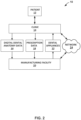
- FIG. 2 is a block diagram illustrating an example computer environment 10 in which clinic 14 and manufacturing facility 20 communicate information throughout a manufacturing process of a set of removable dental appliances 22 for patient 12.
- the set of removable dental appliances 22 may include removable dental appliance 100.
- removable dental appliance 100 includes at least two shells and at least one interproximal reinforcement.
- an orthodontic practitioner of clinic 14 generates one or more images of a dental anatomy of patient 12 using any suitable imaging technique and generates digital dental anatomy data 46 (e.g., a digital representation of patient's 12 tooth structure). For example, the practitioner may generate X-RAY images that can be digitally scanned.
- the digital dental anatomy data 16 may be provided by scanning a negative impression of the teeth of patient 12.
- the digital dental anatomy data 16 may be provided by imaging a positive physical model of the teeth of patient 12 or by using a contact probe on a model of the teeth of patient 12.
- the model used for scanning may be made, for example, by casting an impression of the dentition of patient 12 from a suitable impression material such as alginate or polyvinylsiloxane (PVS), pouring a casting material (such as orthodontic stone or epoxy resin) into the impression, and allowing the casting material to cure.
- Any suitable scanning technique may be used for scanning the model, including those described above. Other possible scanning methods are described in, for example, U.S. Patent No. 9,191,648 (Kriveshko et al. ) and U.S. Patent No. 9,245,374 (McQueston et al. ).
- Segmentation allows a user to characterize and manipulate the teeth arrangement as a set of individual objects.
- the computer may derive diagnostic information such as arch length, bite setting, interstitial spacing between adjacent teeth, and even American Board of Orthodontics (ABO) objective grading from these models.
- ABO American Board of Orthodontics
- the digital orthodontic setups may provide flexibility in the manufacturing process. By replacing physical processes with digital processes, the data acquisition step and data manipulation steps can be executed at separate locations without the need to transport stone models or impressions from one location to another. Reducing or eliminating the need for shipping physical objects back and forth can result in significant cost savings to both customers and manufacturers of customized appliances.
- Clinic 14 may also forward prescription data 18 conveying general information regarding a practitioner's diagnosis and treatment plan for patient 12 to manufacturing facility 20.
- prescription data 18 may be more specific.
- digital dental anatomy data 16 may be a digital representation of the dental anatomy of patient 12.
- the practitioner of clinic 14 may review the digital representation and indicate at least one of desired movements, spacing, or final positions of individual teeth of patient 12.
- the desired movements, spacing, and final positions of individual teeth of patient 12 may affect the forces to be applied to the teeth of patient 12 at each stage of treatment by each removable dental appliance of the set of removable dental appliances 22.
- the 3D digital dental anatomy data 16 may be produced by, for example, forming and subsequently digitally scanning a physical impression or casting of the tooth structure of patient 12.
- a physical impression or casting of a dental arch of patient 12 may be scanned using a visible light scanner, such as an OM-3R scanner (available from Laser Design, Inc. of Minneapolis, Minnesota) or an ATOS scanner (available from GOM GmbH of Braunschweig, Germany).
- the practitioner may generate the 3D digital dental anatomy data 16 of the occlusal service by use of an intra-oral scan of the dental arch of patient 12, or existing 3D tooth data.
- the 3D digital representations may be registered using a software program that enables the 3D representations to be manipulated within a computer environment (e.g., Geomagic Studio software (available from 3D Systems, Inc.; 333 Three D Systems Circle, Rock Hill, South Carolina), or alternatively, registration techniques described in U.S. Patent No. 8,491,306 may be used.
- Geomagic Studio software available from 3D Systems, Inc.; 333 Three D Systems Circle, Rock Hill, South Carolina
- registration techniques described in U.S. Patent No. 8,491,306 may be used.
- User interface 54 provides a graphical user interface (GUI) that visually displays the 3D representation of the teeth of patient 12.
- GUI graphical user interface
- user interface 54 provides an interface for receiving input from practitioner 60, e.g., via a keyboard and a pointing device, a touchscreen, or the like, for manipulating the teeth of patient 12 within the modeled dental arch.
- Modeling software 52 may be accessible to manufacturing facility 20 via network interface 70. Modeling software 52 interacts with database 62 to access a variety of data, such as treatment data 64, 3D data 66 relating to the tooth structure of patient 12, and patient data 68.
- Database 62 may be represented in a variety of forms including data storage files, lookup tables, or a database management system (DBMS) executing on one or more database servers.
- the database management system may be a relational (RDBMS), hierarchical (HDBMS), multi-dimensional (MDBMS), object oriented (ODBMS or OODBMS) or object relational (ORDBMS) database management system.
- the data may, for example, be stored within a single relational database, such as SQL Server from Microsoft Corporation.
- database 62 may be located remote from the client computing device 50 and coupled to the client computing device 50 via a public or private network, e.g., network 24.
- Treatment data 64 describes diagnosis or repositioning information for the teeth of patient 12 selected by practitioner 60 and positioned within the 3D modeling environment.
- treatment data 64 may include the dimensions, shapes, and positions of the interproximal reinforcement (e.g., interproximal reinforcements 102) and shells (e.g., shells 108) that may result in a selected magnitude and direction of force vectors to be applied to patient's teeth (e.g., teeth 106) throughout the treatment plans.
- Patient data 68 describes a set of one or more patients, e.g., patient 12, associated with practitioner 60.
- patient data 68 specifies general information, such as a name, birth date, and a dental history, for each patient 12.
- Rendering engine 58 accesses and renders 3D data 66 to generate the 3D view presented to practitioner 60 by user interface 54. More specifically, 3D data 66 includes information defining the 3D objects that represent each tooth (optionally including roots), and jaw bone within the 3D environment. Rendering engine 58 processes each object to render a 3D triangular mesh based on viewing perspective of practitioner 60 within the 3D environment. User interface 54 displays the rendered 3D triangular mesh to practitioner 60 and allows practitioner 60 to change viewing perspectives and manipulate objects within the 3D environment.
- Client computing device 50 includes processor 72 and memory 74 to store and execute modeling software 52.
- Memory 74 may represent any volatile or non-volatile storage elements. Examples include random access memory (RAM) such as synchronous dynamic random access memory (SDRAM), read-only memory (ROM), non-volatile random access memory (NVRAM), electrically erasable programmable read-only memory (EEPROM), and FLASH memory. Examples may also include non-volatile storage, such as a hard-disk, magnetic tape, a magnetic or optical data storage media, a compact disk (CD), a digital versatile disk (DVD), a Blu-ray disk, and a holographic data storage media.
- RAM random access memory
- SDRAM synchronous dynamic random access memory
- ROM read-only memory
- NVRAM non-volatile random access memory
- EEPROM electrically erasable programmable read-only memory
- FLASH memory FLASH memory
- non-volatile storage such as a hard-disk, magnetic tape, a magnetic or optical data storage media
- Processor 72 represents one or more processors such as a general-purpose microprocessor, a specially designed processor, an application specific integrated circuit (ASIC), a field programmable gate array (FPGA), a collection of discrete logic, or any type of processing device capable of executing the techniques described herein.
- memory 74 may store program instructions (e.g., software instructions) that are executed by processor 72 to carry out the techniques described herein.
- the techniques may be executed by specifically programmed circuitry of processor 72.
- processor 72 may be configured to execute the techniques described herein.
- Computer 80 may further be configured to automatically determine dimensions and shapes of each removable dental appliance of a set of removable dental appliances 22.
- the dimensions and shapes of removable dental appliance 22 may include a position, dimension, and shape of shells and interproximal reinforcements such that removable dental appliance 22 is configured to reposition the one or more teeth from their initial positions to final positions when the removable dental appliance is worn by the patient.
- the position, dimension, and shape of the shells and interproximal reinforcements may affect the magnitude, direction, and length of expression of a force applied to the teeth when the removable dental appliance is worn by the patient.
- the thickness and shape of a respective interproximal reinforcement of a plurality of interproximal reinforcements may determine, at least in part, the magnitude, direction, and length of expression of the force resulting from a deformation of the respective interproximal reinforcement when the removable dental appliance is worn by the patient.
- the locations where a respective interproximal reinforcement is coupled to a respective shell may also determine, at least in part, the direction of the force that may be transferred from a respective interproximal reinforcement to a respective shell.
- the location or locations of engagement of a respective shell with a respective tooth determine the direction of the force applied to the respective tooth.
- Computer 80 may analyze at least one of the magnitude, direction, and length of expression of the force resulting from a deformation of the respective interproximal reinforcement when the removable dental appliance is worn by the patient to determine at least one of position, dimension, and shape of a respective interproximal reinforcement that will result in a desired movement of the patient's teeth when the removable dental appliance is worn by the patient.
- Client computing device 50 and computer 80 are merely conceptual representations of an example computer system.
- the functionalities described with respect to client computing device 50, computer 80, or both may be combined into a single computing device or distributed among multiple computing devices within a computer system.
- cloud computing may be used for digital design of dental appliances described herein.
- the digital representations of tooth structures are received at one computer at the clinic, while a different computer, such as computer 80, is used to determine the shapes and dimensions of a removable dental appliance.
- Shapes and dimensions may be determined, at least in part, based on knowledge derived through analysis of historical cases or virtual models of exemplary cases, without receiving a complete 3D representation of the case in question.
- data transmitted between client computing device 50 and computer 80, or otherwise utilized to design a custom dental appliance may be significantly less than the complete data set representing a complete digital dental model of a patient.
- FIG. 5 is a block diagram illustrating an example computer-aided manufacturing system 700 for construction of removable dental appliance 722.
- computer-aided manufacturing system 700 may include a 3D printer, a fused deposition modeling device, or the like.
- Computer-aided manufacturing system 700 may include an additive manufacturing system 702 in communication with computer 704 and coupled to build material source 710.
- computer-aided manufacturing system 700 may include computer-aided manufacturing system 84 of FIG. 4 .
- computer 704 may be the same as or substantially similar to computer 80.
- Build material source 710 may include a source of at least one polymeric material, such as, for example, at least one of the polymeric materials of appliance body 104 discussed above.
- Dental appliance 722 may be the same as or substantially similar to removable dental appliance 100. In some examples, dental appliance 722 may include one dental appliance of the set of dental appliances 22.
- Additive manufacturing system 702 may include a moveable platform 708 and an extrusion head 706. Movable platform 708 and extrusion head 706 may be configured to manufacture dental appliance 722.
- computer 704 may control extrusion head 706 and moveable platform 708 to manufacture removable dental appliance 722.
- Controlling, by computer 704, extrusion head 706 may include at least one of controlling a material feed rate from build material source 710 to extrusion head 706, controlling a deposition rate of build material on dental appliance 722, controlling a temperature of extrusion head 706, and controlling a position of extrusion head 706.
- computer 704 may control manufacture of a position, dimension, and shape of at least a portion of dental appliance 722.
- Controlling, by computer 704, movable platform 708 may include at least one of controlling a translation of moveable platform in a plane normal to the direction of material deposition from extrusion head 706 and controlling an elevation of moveable platform along an axis substantially parallel to the direction of material deposition from extrusion head 706.
- computer 704 may control manufacture of a position, dimension, and shape of at least a portion of dental appliance 722.
- FIG. 5 illustrates a computer-aided manufacturing system 700 configured for Fused Deposition Modeling (FDM)
- computer-aided manufacturing system 700 may also be configured for stereolithography (SLA), inverse vat polymerization additive manufacturing, inkjet/polyjet additive manufacturing, or other methods of additive manufacturing.
- SLA stereolithography
- inverse vat polymerization additive manufacturing inkjet/polyjet additive manufacturing
- computer-aided manufacturing system 700 may be configured to print multiple materials in a single print, thereby allowing a high modulus material for the rigid components of dental appliance 722 (e.g., interproximal reinforcements 102) and a low modulus or elastomeric material for the less rigid components of dental appliance 722 (e.g., shells 108).
- the modulus may be varied selectively across the dental appliance 722, and a different modulus may be used for the interproximal reinforcement than is used for the shells, for different parts of an interproximal reinforcement, or for different parts of a shell, for example. Similarly, a different modulus may be used for the anchoring shells than is used for the shells used to reposition individual teeth.
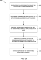
- FIG. 6A-6C are flow diagrams illustrating process 500 conducted at manufacturing facility 20 for construction of the set of removable dental appliances 22.
- set of removable dental appliances 22 may include removable dental appliance 100.
- Computer 80 at manufacturing facility 20 receives digital dental anatomy data 16 including initial positions of one or more teeth of the patient and prescription data 18 (502) from clinic 14.
- computer 80 may retrieve the information from a database located within or otherwise accessible by computer 80.
- a trained user associated with computer 80 may interact with a computerized modeling environment running on computer 80 to develop a treatment plan relative to the digital representation of the patient's tooth structure and generate prescription data 18, if clinic 14 has not already done so.
- computer 80 may automatically develop a treatment plan based solely on the patient's tooth structure and predefined design constraints.
- computer 80 determines dimensions and shapes of a removable dental appliance for the patient (504).
- the dimensions and shapes of the removable dental appliance are configured to reposition the one or more teeth of the patient from their initial positions to final positions when the removable dental appliance is worn by the patient.
- computer 80 determines dimensions and shapes of the set of removable dental appliances 22 for the patient configured to be worn in series.
- determining dimensions and shapes of the removable dental appliance includes selecting, with computer 80, the dimensions and shapes of the removable dental appliance according to a set of predefined design constraints.
- the set of predesigned design constraints may include one or more factors, including, but not limited to, at least one of a minimum and a maximum localized force applied to one or more of the surrounded teeth, at least one of a minimum and a maximum rotational force applied to one or more of the surrounded teeth, at least one of a minimum and a maximum translational force applied to one or more of the surrounded teeth, at least one of a minimum and a maximum total force applied to one or more of the surrounded teeth, and at least one of a minimum and a maximum stress or strain applied to the removable dental appliance, when the removable dental appliance is worn by the patient and the surrounded teeth are in their initial positions.
- Minimum applied forces are necessary to cause pressure on the periodontal ligament sufficient to result in bone remodeling and tooth movement.
- Computer 80 may use finite element analysis (FEA) techniques to analyze forces on a patient's teeth as well as the removable dental appliance during the determination of the dimensions and shapes of the removable dental appliance. For example, computer 80 may apply FEA to a solid model of the patient's teeth as the modeled teeth move from their initial positions to their final positions representing a treatment including an ordered set of removable dental appliances. Computer 80 may use FEA to select the appropriate removable dental appliance to apply the desired forces on the teeth. In addition, computer 80 may use a virtual articulator to determine contact points between the teeth throughout the movement of the modeled teeth during the treatment.
- FEA finite element analysis
- determining dimensions and shapes of removable dental appliance 100 includes selecting, with computer 80 thicknesses of appliance body 104, such as shells 108, and interproximal reinforcements 102, to provide a stiffness suitable to reposition the one or more teeth of the patient from their initial positions to final positions when the removable dental appliance is worn by the patient.
- the dimensions and shapes of a removable dental appliance for the patient may be presented to a user via user interface 82 of computer 80 (506).
- the user may have the opportunity to adjust the design constraints or directly adjust the dimensions and shapes of the removable dental appliance before the design data is sent to computer-aided manufacturing system 84.
- the dimensions and shapes of the removable dental appliance may be presented to a user by computer 80 directly as the removable dental appliance is manufactured by computer-aided manufacturing system 84.
- computer 80 may send a digital model of removable dental appliance 100 to computer-aided manufacturing system 84, and computer-aided manufacturing system 84 manufactures removable dental appliance according to the digital model from computer 80.
- a removable dental appliance for the patient may be presented to a user via user interface of 82 of computer 80
- computer 80 sends a digital model of the removable dental appliance to computer-aided manufacturing system 84 (508)
- computer-aided manufacturing system 84 manufactures removable dental appliance 100 of a set of removable dental appliances 22 according to the digital model from computer 80 (510).
- Manufacturing of removable dental appliances 22 (510) may include 3D printing, thermoforming, injection molding, lost wax casting, 5-axis milling, laser cutting, multi-axis robotic Fused Deposition Modeling (FDM), hybrid plastic and metal manufacturing techniques, such as snap-fitting, overmolding, or electroforming, as well as other manufacturing techniques.
- FDM Fused Deposition Modeling
- manufacturing removable dental appliance 100 includes 3D printing removable dental appliance 100.
- FIG. 6B is a flow diagram illustrating a technique for 3D printing of a removable dental appliances that include an interproximal reinforcement.
- 3D printing removable dental appliance 100 includes preparing the 3D printer (512).
- preparing the 3D printer may include selecting and installing (e.g., loading) one or more polymers, one or more binders, or other materials to be printed by the 3D printer.
- preparing the 3D printer may include creating a stage or form onto which the 3D printer will build-up material.
- Printing removable dental appliance 100 also includes building up the material (514).
- the 3D model may include raised surfaces to facilitate forming at least one of the shells and the interproximal reinforcements in the thermoformed and trimmed appliance body.
- Thermoforming removable dental appliance 100 includes thermoforming appliance body 104 over the 3D model (524).
- thermoforming includes placing a polymer sheet onto the 3D model and heating the polymer sheet to substantially conform (e.g., conform or nearly conform) to the shape of the 3D model.
- thermoforming may use a vacuum to facilitate conformation of the heated polymer sheet to the 3D model.
- Thermoforming removable dental appliance 100 includes trimming excess material from the applicant body to form the shells and the interproximal reinforcements (526). In some examples, trimming may be performed manually or automated by CNC or robotic machinery such as, e.g., end mill or LASER cutter.
- thermoforming and 3D-printing may be used to form different portions of an appliance body.
- shells 108 may be formed by thermoforming, as discussed above, whereas interproximal reinforcements 102 may be formed by 3D printing onto the thermoformed shells 108.
- the techniques described with respect to FIGS. 6A-6C may be embodied within a computer-readable storage medium, such as a computer-readable storage medium of computing device 50, computer 80, or both.
- the computer-readable storage medium may store computer-executable instructions that, when executed, configure a processor to perform the techniques described with respect to FIGS. 6A-6C .
- each removable dental appliance in the ordered set of removable dental appliances 22 may be configured to incrementally reposition the teeth of the patient.
- the ordered set of removable dental appliances 22 may be configured to reposition the teeth of the patient to a greater degree than any one of the removable dental appliances within the set of the removable dental appliances 22.
- Such an ordered set of removable dental appliances 22 may specifically be configured to incrementally reposition the one or more teeth of the patient from their initial positions to final positions as the removable dental appliances of the ordered set of removable dental appliances 22 for the patient are worn sequentially by the patient.
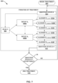
- the patient may return to the clinician who may evaluate the result of the first iteration of treatment (614). If the first iteration of treatment has resulted in acceptable final positions of the patient's teeth, then the treatment may be ended (616). However, if the first iteration of treatment did not result in acceptable final positions of the patient's teeth, one or more additional iterations of treatment may be performed. To begin the next iteration of treatment, the clinician may take another scan of the patient's teeth to facilitate the design of a subsequent ordered set of removable dental appliances (606).
- FIG. 14 illustrates measured force (e.g., moment, N-mm) in a clockwise direction (e.g., a "Clockwise Rotation") applied to tooth models 904 versus rotation (deg) for removable dental appliances 902 using the Attachment and the Wire IR.
- the results illustrate the ability of the interproximal reinforcements to resist tooth rotation caused by a rotational moment applied to the tooth.
- the similar performance of the interproximal reinforcement and tooth attachment indicate interproximal reinforcement may be as effective as tooth attachments at rotating malposed teeth toward the desired rotational angle.
- FIG. 15 illustrates measured force (kilogram, "kg") applied in a distal direction, (e.g., a "distal push") applied to tooth models 904 versus displacement (millimeters, "mm") for removable dental appliance 902 using an attachment fixed to the model right first bicuspid 904A (“Attachment”) and using a polymeric interproximal reinforcement applied by stereolithography (SLA) at the model left first bicuspid 904B (“SLA IR”).
- FIG. 16 illustrates measured force in a labial direction (e.g., a "labial push”) applied to tooth models 904 versus displacement (mm) for removable dental appliances 902 using the Attachment and the SLA IR.
- FIGS. 19 and 20 Results for moments applied to the tooth models 904 are shown in FIGS. 19 and 20 .
- the angular rotations shown in FIGS. 19 and 20 have been corrected to remove the apparent rotation component caused by elastic deformation of the metal pin.
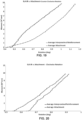
- FIG. 19 illustrates measured force (e.g., moment, Newton-millimeter (“N-mm”)) in a counter clockwise direction (e.g., a "Counter Clockwise Rotation”) applied to tooth models 904 versus rotation (degrees, "deg") for removable dental appliances 902 using the Attachment and the SLA IR.
- FIG. 19 illustrates measured force (e.g., moment, Newton-millimeter (“N-mm”)) in a counter clockwise direction (e.g., a "Counter Clockwise Rotation") applied to tooth models 904 versus rotation (degrees, "deg") for removable dental appliances 902 using the Attachment and the SLA IR.
- N-mm a counter clockwise direction
Landscapes
- Health & Medical Sciences (AREA)
- Life Sciences & Earth Sciences (AREA)
- Public Health (AREA)
- Animal Behavior & Ethology (AREA)
- Veterinary Medicine (AREA)
- General Health & Medical Sciences (AREA)
- Oral & Maxillofacial Surgery (AREA)
- Dentistry (AREA)
- Epidemiology (AREA)
- Engineering & Computer Science (AREA)
- General Engineering & Computer Science (AREA)
- Materials Engineering (AREA)
- Manufacturing & Machinery (AREA)
- Chemical & Material Sciences (AREA)
- Dental Tools And Instruments Or Auxiliary Dental Instruments (AREA)
- Biomedical Technology (AREA)
- Biophysics (AREA)
- Dental Preparations (AREA)
Applications Claiming Priority (3)
| Application Number | Priority Date | Filing Date | Title |
|---|---|---|---|
| US201862767837P | 2018-11-15 | 2018-11-15 | |
| PCT/IB2019/059555 WO2020099990A1 (fr) | 2018-11-15 | 2019-11-06 | Appareil dentaire amovible à renforcement interproximal |
| EP19885292.3A EP3880113B1 (fr) | 2018-11-15 | 2019-11-06 | Appareil dentaire amovible à renforcement interproximal |
Related Parent Applications (1)
| Application Number | Title | Priority Date | Filing Date |
|---|---|---|---|
| EP19885292.3A Division EP3880113B1 (fr) | 2018-11-15 | 2019-11-06 | Appareil dentaire amovible à renforcement interproximal |
Publications (3)
| Publication Number | Publication Date |
|---|---|
| EP4393707A2 true EP4393707A2 (fr) | 2024-07-03 |
| EP4393707A3 EP4393707A3 (fr) | 2024-09-11 |
| EP4393707B1 EP4393707B1 (fr) | 2025-09-10 |
Family
ID=70732091
Family Applications (2)
| Application Number | Title | Priority Date | Filing Date |
|---|---|---|---|
| EP24173374.0A Active EP4393707B1 (fr) | 2018-11-15 | 2019-11-06 | Appareil dentaire amovible a renforcement interproximal |
| EP19885292.3A Active EP3880113B1 (fr) | 2018-11-15 | 2019-11-06 | Appareil dentaire amovible à renforcement interproximal |
Family Applications After (1)
| Application Number | Title | Priority Date | Filing Date |
|---|---|---|---|
| EP19885292.3A Active EP3880113B1 (fr) | 2018-11-15 | 2019-11-06 | Appareil dentaire amovible à renforcement interproximal |
Country Status (7)
| Country | Link |
|---|---|
| US (2) | US11737855B2 (fr) |
| EP (2) | EP4393707B1 (fr) |
| JP (1) | JP7741728B2 (fr) |
| KR (1) | KR102773399B1 (fr) |
| CN (1) | CN113056240B (fr) |
| AU (1) | AU2019381318B2 (fr) |
| WO (1) | WO2020099990A1 (fr) |
Families Citing this family (7)
| Publication number | Priority date | Publication date | Assignee | Title |
|---|---|---|---|---|
| US20200229898A1 (en) * | 2014-03-13 | 2020-07-23 | Melikset Litvinovich MELIKYAN | Wire mesh composite prosthesis |
| ES3008311T3 (en) | 2018-11-15 | 2025-03-21 | Solventum Intellectual Properties Company | Removable dental appliance with gingival ridges |
| US12263058B2 (en) | 2019-12-27 | 2025-04-01 | Solventum Intellectual Properties Company | Preformed orthodontic aligner attachments |
| WO2022142487A1 (fr) * | 2020-12-31 | 2022-07-07 | 正雅齿科科技(上海)有限公司 | Système de traitement orthodontique, son procédé de conception et son procédé de préparation |
| US20220249204A1 (en) * | 2021-02-08 | 2022-08-11 | Fahed Yusef Simon Tuma | Mouth Guard System and Method of Use |
| US20220313393A1 (en) * | 2021-04-02 | 2022-10-06 | Align Technology, Inc. | Orthodontic appliances with edge profiles for optimized tooth movement and methods for forming the same |
| WO2026023918A1 (fr) * | 2024-07-26 | 2026-01-29 | 오스템임플란트 주식회사 | Appareils dentaires transparents |
Citations (11)
| Publication number | Priority date | Publication date | Assignee | Title |
|---|---|---|---|---|
| US6845175B2 (en) | 1998-11-01 | 2005-01-18 | Cadent Ltd. | Dental image processing method and system |
| US7027642B2 (en) | 2000-04-28 | 2006-04-11 | Orametrix, Inc. | Methods for registration of three-dimensional frames to create three-dimensional virtual models of objects |
| US7234937B2 (en) | 1999-11-30 | 2007-06-26 | Orametrix, Inc. | Unified workstation for virtual craniofacial diagnosis, treatment planning and therapeutics |
| WO2007084727A1 (fr) | 2006-01-20 | 2007-07-26 | 3M Innovative Properties Company | Dentistrie numerique |
| US7731495B2 (en) | 2005-12-20 | 2010-06-08 | 3M Innovative Properties Company | User interface having cross section control tool for digital orthodontics |
| US8194067B2 (en) | 2004-02-04 | 2012-06-05 | 3M Innovative Properties Company | Planar guides to visually aid orthodontic appliance placement within a three-dimensional (3D) environment |
| US8491306B2 (en) | 2005-08-03 | 2013-07-23 | 3M Innovative Properties Company | Registering physical and virtual tooth structures with pedestals |
| US8738165B2 (en) | 2007-12-21 | 2014-05-27 | 3M Innovative Properties Company | Methods of preparing a virtual dentition model and fabricating a dental retainer therefrom |
| US8897902B2 (en) | 2011-02-18 | 2014-11-25 | 3M Innovative Properties Company | Orthodontic digital setups |
| US9191648B2 (en) | 2011-02-22 | 2015-11-17 | 3M Innovative Properties Company | Hybrid stitching |
| US9245374B2 (en) | 2011-02-22 | 2016-01-26 | 3M Innovative Properties Company | Space carving in 3D data acquisition |
Family Cites Families (30)
| Publication number | Priority date | Publication date | Assignee | Title |
|---|---|---|---|---|
| US3837081A (en) * | 1973-07-02 | 1974-09-24 | P Kesling | Preformed tooth positioning and retaining appliance |
| US5145364A (en) * | 1991-05-15 | 1992-09-08 | M-B Orthodontics, Inc. | Removable orthodontic appliance |
| US6572372B1 (en) * | 2000-04-25 | 2003-06-03 | Align Technology, Inc. | Embedded features and methods of a dental appliance |
| US7121825B2 (en) * | 1998-11-30 | 2006-10-17 | Align Technology, Inc. | Tooth positioning appliances and systems |
| US6524101B1 (en) * | 2000-04-25 | 2003-02-25 | Align Technology, Inc. | System and methods for varying elastic modulus appliances |
| US20060199142A1 (en) | 2005-03-07 | 2006-09-07 | Liu Frank Z | Dental aligner for providing accurate dental treatment |
| US7831322B2 (en) | 2005-03-07 | 2010-11-09 | Align Technology, Inc. | Producing wrinkled dental aligner for dental treatment |
| US20080057457A1 (en) * | 2006-08-30 | 2008-03-06 | Inman Donal P | Clasp for removable dental appliances |
| US7914283B2 (en) | 2007-12-06 | 2011-03-29 | Align Technology, Inc. | Activatable dental appliance |
| US8899977B2 (en) | 2008-01-29 | 2014-12-02 | Align Technology, Inc. | Orthodontic repositioning appliances having improved geometry, methods and systems |
| US8517726B2 (en) | 2008-09-12 | 2013-08-27 | Align Technology, Inc. | Dental appliance with resilient portion |
| US20100075269A1 (en) * | 2008-09-22 | 2010-03-25 | Ortho Organizers, Inc. | Accessory mounting clip for orthodontic aligner trays |
| US8152518B2 (en) | 2008-10-08 | 2012-04-10 | Align Technology, Inc. | Dental positioning appliance having metallic portion |
| US8356993B1 (en) * | 2009-07-06 | 2013-01-22 | Marston Blake E | Orthodontic appliance system |
| US9241774B2 (en) | 2010-04-30 | 2016-01-26 | Align Technology, Inc. | Patterned dental positioning appliance |
| US20110269092A1 (en) * | 2010-04-30 | 2011-11-03 | Align Technology, Inc. | Reinforced aligner hooks |
| US20130230819A1 (en) | 2011-12-15 | 2013-09-05 | Airton Arruda | Apparatus for orthodontic aligner tray retention |
| US9022781B2 (en) | 2012-02-15 | 2015-05-05 | Align Technology, Inc. | Orthodontic appliances that accommodate incremental and continuous tooth movement, systems and methods |
| US20130236848A1 (en) * | 2012-03-06 | 2013-09-12 | Airton Arruda | Method for orthodontic treatment |
| US20140242532A1 (en) * | 2012-03-06 | 2014-08-28 | Airton Arruda | Method for orthodontic treatment |
| EP3900664B1 (fr) * | 2014-01-31 | 2025-09-24 | Align Technology, Inc. | Appareils orthodontiques ayant des élastiques |
| EP3119347B1 (fr) * | 2014-03-21 | 2023-06-07 | Align Technology, Inc. | Appareil orthodontique segmenté doté d'élastiques |
| BR112017014209A2 (pt) * | 2014-12-30 | 2018-03-06 | 3M Innovative Properties Company | design de aparelhos dentários auxiliado por sistema de computador |
| US11045282B2 (en) * | 2015-07-07 | 2021-06-29 | Align Technology, Inc. | Direct fabrication of aligners with interproximal force coupling |
| US10874483B2 (en) | 2015-07-07 | 2020-12-29 | Align Technology, Inc. | Direct fabrication of attachment templates with adhesive |
| US10363116B2 (en) | 2015-07-07 | 2019-07-30 | Align Technology, Inc. | Direct fabrication of power arms |
| WO2018167616A1 (fr) * | 2017-03-15 | 2018-09-20 | 3M Innovative Properties Company | Appareil orthodontique amovible |
| WO2019069162A1 (fr) * | 2017-10-06 | 2019-04-11 | 3M Innovative Properties Company | Appareil dentaire amovible comprenant des soufflets à ressort |
| US10792128B2 (en) * | 2017-11-30 | 2020-10-06 | Richter Orthodontics, P.C. | Orthodontic settling retainer |
| US11000404B2 (en) * | 2018-03-01 | 2021-05-11 | Richard D. Hamburg | Oral appliance |
-
2019
- 2019-11-06 EP EP24173374.0A patent/EP4393707B1/fr active Active
- 2019-11-06 CN CN201980075390.XA patent/CN113056240B/zh active Active
- 2019-11-06 US US17/290,297 patent/US11737855B2/en active Active
- 2019-11-06 JP JP2021526482A patent/JP7741728B2/ja active Active
- 2019-11-06 AU AU2019381318A patent/AU2019381318B2/en active Active
- 2019-11-06 EP EP19885292.3A patent/EP3880113B1/fr active Active
- 2019-11-06 WO PCT/IB2019/059555 patent/WO2020099990A1/fr not_active Ceased
- 2019-11-06 KR KR1020217016906A patent/KR102773399B1/ko active Active
-
2023
- 2023-07-12 US US18/221,010 patent/US12582506B2/en active Active
Patent Citations (11)
| Publication number | Priority date | Publication date | Assignee | Title |
|---|---|---|---|---|
| US6845175B2 (en) | 1998-11-01 | 2005-01-18 | Cadent Ltd. | Dental image processing method and system |
| US7234937B2 (en) | 1999-11-30 | 2007-06-26 | Orametrix, Inc. | Unified workstation for virtual craniofacial diagnosis, treatment planning and therapeutics |
| US7027642B2 (en) | 2000-04-28 | 2006-04-11 | Orametrix, Inc. | Methods for registration of three-dimensional frames to create three-dimensional virtual models of objects |
| US8194067B2 (en) | 2004-02-04 | 2012-06-05 | 3M Innovative Properties Company | Planar guides to visually aid orthodontic appliance placement within a three-dimensional (3D) environment |
| US8491306B2 (en) | 2005-08-03 | 2013-07-23 | 3M Innovative Properties Company | Registering physical and virtual tooth structures with pedestals |
| US7731495B2 (en) | 2005-12-20 | 2010-06-08 | 3M Innovative Properties Company | User interface having cross section control tool for digital orthodontics |
| WO2007084727A1 (fr) | 2006-01-20 | 2007-07-26 | 3M Innovative Properties Company | Dentistrie numerique |
| US8738165B2 (en) | 2007-12-21 | 2014-05-27 | 3M Innovative Properties Company | Methods of preparing a virtual dentition model and fabricating a dental retainer therefrom |
| US8897902B2 (en) | 2011-02-18 | 2014-11-25 | 3M Innovative Properties Company | Orthodontic digital setups |
| US9191648B2 (en) | 2011-02-22 | 2015-11-17 | 3M Innovative Properties Company | Hybrid stitching |
| US9245374B2 (en) | 2011-02-22 | 2016-01-26 | 3M Innovative Properties Company | Space carving in 3D data acquisition |
Also Published As
| Publication number | Publication date |
|---|---|
| WO2020099990A1 (fr) | 2020-05-22 |
| JP7741728B2 (ja) | 2025-09-18 |
| EP3880113A1 (fr) | 2021-09-22 |
| KR20210089702A (ko) | 2021-07-16 |
| US20220015869A1 (en) | 2022-01-20 |
| EP3880113B1 (fr) | 2024-05-01 |
| AU2019381318B2 (en) | 2023-04-13 |
| JP2022507499A (ja) | 2022-01-18 |
| CN113056240A (zh) | 2021-06-29 |
| EP3880113A4 (fr) | 2022-08-03 |
| US11737855B2 (en) | 2023-08-29 |
| EP4393707B1 (fr) | 2025-09-10 |
| EP4393707A3 (fr) | 2024-09-11 |
| AU2019381318A1 (en) | 2021-05-27 |
| CN113056240B (zh) | 2022-08-02 |
| KR102773399B1 (ko) | 2025-02-25 |
| US12582506B2 (en) | 2026-03-24 |
| US20230390028A1 (en) | 2023-12-07 |
Similar Documents
| Publication | Publication Date | Title |
|---|---|---|
| US12239507B2 (en) | Removable dental appliance with gingival ridges | |
| US12582506B2 (en) | Removable dental appliance with interproximal reinforcement | |
| US11446117B2 (en) | Removable dental appliance including positioning member | |
| EP3691560B1 (fr) | Appareil dentaire amovible comprenant des soufflets à ressort | |
| US20200397537A1 (en) | Removable dental appliance including bendable flaps | |
| US20220211470A1 (en) | Removable dental appliances including bendable flaps and arcuate members | |
| WO2019069164A1 (fr) | Appareil dentaire amovible comprenant des cavaliers |
Legal Events
| Date | Code | Title | Description |
|---|---|---|---|
| PUAI | Public reference made under article 153(3) epc to a published international application that has entered the european phase |
Free format text: ORIGINAL CODE: 0009012 |
|
| STAA | Information on the status of an ep patent application or granted ep patent |
Free format text: STATUS: THE APPLICATION HAS BEEN PUBLISHED |
|
| AC | Divisional application: reference to earlier application |
Ref document number: 3880113 Country of ref document: EP Kind code of ref document: P |
|
| AK | Designated contracting states |
Kind code of ref document: A2 Designated state(s): AL AT BE BG CH CY CZ DE DK EE ES FI FR GB GR HR HU IE IS IT LI LT LU LV MC MK MT NL NO PL PT RO RS SE SI SK SM TR |
|
| PUAL | Search report despatched |
Free format text: ORIGINAL CODE: 0009013 |
|
| RIN1 | Information on inventor provided before grant (corrected) |
Inventor name: RABY, RICHARD E. Inventor name: CINADER, DAVID K., JR. Inventor name: DOMROESE, MICHAEL K. |
|
| AK | Designated contracting states |
Kind code of ref document: A3 Designated state(s): AL AT BE BG CH CY CZ DE DK EE ES FI FR GB GR HR HU IE IS IT LI LT LU LV MC MK MT NL NO PL PT RO RS SE SI SK SM TR |
|
| RIC1 | Information provided on ipc code assigned before grant |
Ipc: A61C 7/08 20060101ALI20240807BHEP Ipc: B33Y 80/00 20150101AFI20240807BHEP |
|
| STAA | Information on the status of an ep patent application or granted ep patent |
Free format text: STATUS: REQUEST FOR EXAMINATION WAS MADE |
|
| 17P | Request for examination filed |
Effective date: 20250306 |
|
| GRAP | Despatch of communication of intention to grant a patent |
Free format text: ORIGINAL CODE: EPIDOSNIGR1 |
|
| STAA | Information on the status of an ep patent application or granted ep patent |
Free format text: STATUS: GRANT OF PATENT IS INTENDED |
|
| INTG | Intention to grant announced |
Effective date: 20250513 |
|
| GRAS | Grant fee paid |
Free format text: ORIGINAL CODE: EPIDOSNIGR3 |
|
| GRAA | (expected) grant |
Free format text: ORIGINAL CODE: 0009210 |
|
| STAA | Information on the status of an ep patent application or granted ep patent |
Free format text: STATUS: THE PATENT HAS BEEN GRANTED |
|
| AC | Divisional application: reference to earlier application |
Ref document number: 3880113 Country of ref document: EP Kind code of ref document: P |
|
| AK | Designated contracting states |
Kind code of ref document: B1 Designated state(s): AL AT BE BG CH CY CZ DE DK EE ES FI FR GB GR HR HU IE IS IT LI LT LU LV MC MK MT NL NO PL PT RO RS SE SI SK SM TR |
|
| REG | Reference to a national code |
Ref country code: GB Ref legal event code: FG4D |
|
| REG | Reference to a national code |
Ref country code: CH Ref legal event code: EP |
|
| REG | Reference to a national code |
Ref country code: DE Ref legal event code: R096 Ref document number: 602019075737 Country of ref document: DE |
|
| REG | Reference to a national code |
Ref country code: IE Ref legal event code: FG4D |
|
| PG25 | Lapsed in a contracting state [announced via postgrant information from national office to epo] |
Ref country code: NO Free format text: LAPSE BECAUSE OF FAILURE TO SUBMIT A TRANSLATION OF THE DESCRIPTION OR TO PAY THE FEE WITHIN THE PRESCRIBED TIME-LIMIT Effective date: 20251210 |
|
| REG | Reference to a national code |
Ref country code: LT Ref legal event code: MG9D |
|
| PG25 | Lapsed in a contracting state [announced via postgrant information from national office to epo] |
Ref country code: FI Free format text: LAPSE BECAUSE OF FAILURE TO SUBMIT A TRANSLATION OF THE DESCRIPTION OR TO PAY THE FEE WITHIN THE PRESCRIBED TIME-LIMIT Effective date: 20250910 |
|
| REG | Reference to a national code |
Ref country code: NL Ref legal event code: MP Effective date: 20250910 |
|
| PG25 | Lapsed in a contracting state [announced via postgrant information from national office to epo] |
Ref country code: HR Free format text: LAPSE BECAUSE OF FAILURE TO SUBMIT A TRANSLATION OF THE DESCRIPTION OR TO PAY THE FEE WITHIN THE PRESCRIBED TIME-LIMIT Effective date: 20250910 |
|
| PG25 | Lapsed in a contracting state [announced via postgrant information from national office to epo] |
Ref country code: GR Free format text: LAPSE BECAUSE OF FAILURE TO SUBMIT A TRANSLATION OF THE DESCRIPTION OR TO PAY THE FEE WITHIN THE PRESCRIBED TIME-LIMIT Effective date: 20251211 |
|
| PG25 | Lapsed in a contracting state [announced via postgrant information from national office to epo] |
Ref country code: SE Free format text: LAPSE BECAUSE OF FAILURE TO SUBMIT A TRANSLATION OF THE DESCRIPTION OR TO PAY THE FEE WITHIN THE PRESCRIBED TIME-LIMIT Effective date: 20250910 |
|
| PG25 | Lapsed in a contracting state [announced via postgrant information from national office to epo] |
Ref country code: LV Free format text: LAPSE BECAUSE OF FAILURE TO SUBMIT A TRANSLATION OF THE DESCRIPTION OR TO PAY THE FEE WITHIN THE PRESCRIBED TIME-LIMIT Effective date: 20250910 |
|
| PG25 | Lapsed in a contracting state [announced via postgrant information from national office to epo] |
Ref country code: PL Free format text: LAPSE BECAUSE OF FAILURE TO SUBMIT A TRANSLATION OF THE DESCRIPTION OR TO PAY THE FEE WITHIN THE PRESCRIBED TIME-LIMIT Effective date: 20250910 Ref country code: BG Free format text: LAPSE BECAUSE OF FAILURE TO SUBMIT A TRANSLATION OF THE DESCRIPTION OR TO PAY THE FEE WITHIN THE PRESCRIBED TIME-LIMIT Effective date: 20250910 |
|
| PG25 | Lapsed in a contracting state [announced via postgrant information from national office to epo] |
Ref country code: RS Free format text: LAPSE BECAUSE OF FAILURE TO SUBMIT A TRANSLATION OF THE DESCRIPTION OR TO PAY THE FEE WITHIN THE PRESCRIBED TIME-LIMIT Effective date: 20251210 |
|
| PG25 | Lapsed in a contracting state [announced via postgrant information from national office to epo] |
Ref country code: ES Free format text: LAPSE BECAUSE OF FAILURE TO SUBMIT A TRANSLATION OF THE DESCRIPTION OR TO PAY THE FEE WITHIN THE PRESCRIBED TIME-LIMIT Effective date: 20250910 |
|
| REG | Reference to a national code |
Ref country code: AT Ref legal event code: MK05 Ref document number: 1835493 Country of ref document: AT Kind code of ref document: T Effective date: 20250910 |
|
| PG25 | Lapsed in a contracting state [announced via postgrant information from national office to epo] |
Ref country code: NL Free format text: LAPSE BECAUSE OF FAILURE TO SUBMIT A TRANSLATION OF THE DESCRIPTION OR TO PAY THE FEE WITHIN THE PRESCRIBED TIME-LIMIT Effective date: 20250910 |
|
| PG25 | Lapsed in a contracting state [announced via postgrant information from national office to epo] |
Ref country code: SM Free format text: LAPSE BECAUSE OF FAILURE TO SUBMIT A TRANSLATION OF THE DESCRIPTION OR TO PAY THE FEE WITHIN THE PRESCRIBED TIME-LIMIT Effective date: 20250910 |
|
| PG25 | Lapsed in a contracting state [announced via postgrant information from national office to epo] |
Ref country code: AT Free format text: LAPSE BECAUSE OF FAILURE TO SUBMIT A TRANSLATION OF THE DESCRIPTION OR TO PAY THE FEE WITHIN THE PRESCRIBED TIME-LIMIT Effective date: 20250910 |
|
| PG25 | Lapsed in a contracting state [announced via postgrant information from national office to epo] |
Ref country code: IT Free format text: LAPSE BECAUSE OF FAILURE TO SUBMIT A TRANSLATION OF THE DESCRIPTION OR TO PAY THE FEE WITHIN THE PRESCRIBED TIME-LIMIT Effective date: 20250910 Ref country code: RO Free format text: LAPSE BECAUSE OF FAILURE TO SUBMIT A TRANSLATION OF THE DESCRIPTION OR TO PAY THE FEE WITHIN THE PRESCRIBED TIME-LIMIT Effective date: 20250910 |
|
| PG25 | Lapsed in a contracting state [announced via postgrant information from national office to epo] |
Ref country code: IS Free format text: LAPSE BECAUSE OF FAILURE TO SUBMIT A TRANSLATION OF THE DESCRIPTION OR TO PAY THE FEE WITHIN THE PRESCRIBED TIME-LIMIT Effective date: 20260110 |
|
| PG25 | Lapsed in a contracting state [announced via postgrant information from national office to epo] |
Ref country code: CZ Free format text: LAPSE BECAUSE OF FAILURE TO SUBMIT A TRANSLATION OF THE DESCRIPTION OR TO PAY THE FEE WITHIN THE PRESCRIBED TIME-LIMIT Effective date: 20250910 Ref country code: PT Free format text: LAPSE BECAUSE OF FAILURE TO SUBMIT A TRANSLATION OF THE DESCRIPTION OR TO PAY THE FEE WITHIN THE PRESCRIBED TIME-LIMIT Effective date: 20260112 |
|
| PG25 | Lapsed in a contracting state [announced via postgrant information from national office to epo] |
Ref country code: EE Free format text: LAPSE BECAUSE OF FAILURE TO SUBMIT A TRANSLATION OF THE DESCRIPTION OR TO PAY THE FEE WITHIN THE PRESCRIBED TIME-LIMIT Effective date: 20250910 Ref country code: SK Free format text: LAPSE BECAUSE OF FAILURE TO SUBMIT A TRANSLATION OF THE DESCRIPTION OR TO PAY THE FEE WITHIN THE PRESCRIBED TIME-LIMIT Effective date: 20250910 |