EP4393715B1 - Flüssigkeitsversorgungsvorrichtung und flüssigkeitsauftragsvorrichtung - Google Patents
Flüssigkeitsversorgungsvorrichtung und flüssigkeitsauftragsvorrichtung Download PDFInfo
- Publication number
- EP4393715B1 EP4393715B1 EP23218124.8A EP23218124A EP4393715B1 EP 4393715 B1 EP4393715 B1 EP 4393715B1 EP 23218124 A EP23218124 A EP 23218124A EP 4393715 B1 EP4393715 B1 EP 4393715B1
- Authority
- EP
- European Patent Office
- Prior art keywords
- ink
- pressure
- liquid
- flow path
- discharge head
- Prior art date
- Legal status (The legal status is an assumption and is not a legal conclusion. Google has not performed a legal analysis and makes no representation as to the accuracy of the status listed.)
- Active
Links
Images






Classifications
-
- B—PERFORMING OPERATIONS; TRANSPORTING
- B41—PRINTING; LINING MACHINES; TYPEWRITERS; STAMPS
- B41J—TYPEWRITERS; SELECTIVE PRINTING MECHANISMS, i.e. MECHANISMS PRINTING OTHERWISE THAN FROM A FORME; CORRECTION OF TYPOGRAPHICAL ERRORS
- B41J2/00—Typewriters or selective printing mechanisms characterised by the printing or marking process for which they are designed
- B41J2/005—Typewriters or selective printing mechanisms characterised by the printing or marking process for which they are designed characterised by bringing liquid or particles selectively into contact with a printing material
- B41J2/01—Ink jet
- B41J2/17—Ink jet characterised by ink handling
- B41J2/175—Ink supply systems ; Circuit parts therefor
- B41J2/17596—Ink pumps, ink valves
-
- B—PERFORMING OPERATIONS; TRANSPORTING
- B41—PRINTING; LINING MACHINES; TYPEWRITERS; STAMPS
- B41J—TYPEWRITERS; SELECTIVE PRINTING MECHANISMS, i.e. MECHANISMS PRINTING OTHERWISE THAN FROM A FORME; CORRECTION OF TYPOGRAPHICAL ERRORS
- B41J2/00—Typewriters or selective printing mechanisms characterised by the printing or marking process for which they are designed
- B41J2/005—Typewriters or selective printing mechanisms characterised by the printing or marking process for which they are designed characterised by bringing liquid or particles selectively into contact with a printing material
- B41J2/01—Ink jet
- B41J2/17—Ink jet characterised by ink handling
- B41J2/175—Ink supply systems ; Circuit parts therefor
- B41J2/17503—Ink cartridges
- B41J2/17556—Means for regulating the pressure in the cartridge
-
- B—PERFORMING OPERATIONS; TRANSPORTING
- B41—PRINTING; LINING MACHINES; TYPEWRITERS; STAMPS
- B41J—TYPEWRITERS; SELECTIVE PRINTING MECHANISMS, i.e. MECHANISMS PRINTING OTHERWISE THAN FROM A FORME; CORRECTION OF TYPOGRAPHICAL ERRORS
- B41J2/00—Typewriters or selective printing mechanisms characterised by the printing or marking process for which they are designed
- B41J2/005—Typewriters or selective printing mechanisms characterised by the printing or marking process for which they are designed characterised by bringing liquid or particles selectively into contact with a printing material
- B41J2/01—Ink jet
- B41J2/17—Ink jet characterised by ink handling
-
- B—PERFORMING OPERATIONS; TRANSPORTING
- B41—PRINTING; LINING MACHINES; TYPEWRITERS; STAMPS
- B41J—TYPEWRITERS; SELECTIVE PRINTING MECHANISMS, i.e. MECHANISMS PRINTING OTHERWISE THAN FROM A FORME; CORRECTION OF TYPOGRAPHICAL ERRORS
- B41J2/00—Typewriters or selective printing mechanisms characterised by the printing or marking process for which they are designed
- B41J2/005—Typewriters or selective printing mechanisms characterised by the printing or marking process for which they are designed characterised by bringing liquid or particles selectively into contact with a printing material
- B41J2/01—Ink jet
- B41J2/17—Ink jet characterised by ink handling
- B41J2/175—Ink supply systems ; Circuit parts therefor
-
- B—PERFORMING OPERATIONS; TRANSPORTING
- B41—PRINTING; LINING MACHINES; TYPEWRITERS; STAMPS
- B41J—TYPEWRITERS; SELECTIVE PRINTING MECHANISMS, i.e. MECHANISMS PRINTING OTHERWISE THAN FROM A FORME; CORRECTION OF TYPOGRAPHICAL ERRORS
- B41J2/00—Typewriters or selective printing mechanisms characterised by the printing or marking process for which they are designed
- B41J2/005—Typewriters or selective printing mechanisms characterised by the printing or marking process for which they are designed characterised by bringing liquid or particles selectively into contact with a printing material
- B41J2/01—Ink jet
- B41J2/17—Ink jet characterised by ink handling
- B41J2/18—Ink recirculation systems
Definitions
- Embodiments of the present disclosure relate to a liquid supply apparatus and a liquid discharge apparatus.
- an ink supply apparatus that supplies ink and the like, as typified by an inkjet, in order to convey a high-viscosity ink having a large amount of solid components and high settleability in a dispersed state
- a technology that relates to an operation is known (which, hereinafter, may be referred to as flow-through) in which the ink is conveyed by being circulated by taking, as part of the flow path, a liquid chamber for the ink in the discharge head.
- an airless spray for which a high pressure is applied to the ink and the ink is vigorously discharged from a spray gun tip hole to atomize and coat the ink.
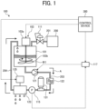
- FIG. 1 is a diagram illustrating a configuration of an ink supply apparatus according to a first embodiment of the present disclosure.
- FIGS. 2A to 2C are diagrams each illustrating a structure of an accumulator of the ink supply apparatus according to the first embodiment.
- FIGS. 3A and 3B are diagrams each illustrating a structure of a piston pressing mechanism that can be substituted for the accumulator of the ink supply apparatus according to the first embodiment.
- FIGS. 4A and 4B are diagrams each illustrating a structure of a subtank that can be substituted for the accumulator of the ink supply apparatus according to the first embodiment.
- a configuration of an ink supply apparatus 100 according to the present embodiment will be described with reference to FIGS. 1 to 4B .
- the ink supply apparatus 100 is an apparatus for forming an image on a print medium by discharging a high-viscosity ink (hereinafter, the ink is sometimes referred to as high-viscosity ink or simply ink) from a discharge head 123 while causing the high-viscosity ink, which is a non-Newtonian fluid having thixotropy, to flow through.
- the ink will be described as an example, but the present invention can be generally applied to a high-viscosity liquid which is a non-Newtonian fluid having thixotropy. As illustrated in FIG.
- the ink supply apparatus 100 includes a high-pressure air supply source 200 (compressed air supply source), a regulator 111, a pressurizing tank 101, a stirring device 103, a pump 121 (an example of a feeder), a filter 122, an accumulator 131 (an example of a first mitigation device), a pressure gauge 115, a discharge head 123, a nozzle open-close control device 125, a pressure control device 117 (first control device), and a control device 300.
- the high-pressure air supply source 200 is coupled to the pressurizing tank 101 via an air supply path 201, and is an air supply source for sending high-pressure air compressed by a compressor or the like to the pressurizing tank 101.
- the high-pressure air supply source 200 sends, for example, air compressed to a pressure equal to or greater than atmospheric pressure to the pressurizing tank 101.
- the regulator 111 is a regulator device that is installed on the air supply path 201 and that reduces the pressure of the high-pressure air supplied from the high-pressure air supply source 200 to a given pressure. That is, the regulator 111 adjusts the pressure of the air supplied from the air supply path 201 to a given pressure greater than atmospheric pressure and lower than the pressure of the air compressed by the high-pressure air supply source 200, and uses the air at that pressure to pressurize an ink IK1, which is the high-viscosity ink with which the pressurizing tank 101 is filled. Adjustment of the pressure reduction by the regulator 111 is performed manually, for example.
- the pressurizing tank 101 is a tank filled with the ink IK1, which is a high-viscosity ink.
- the air supply path 201 is coupled to an upper portion of the pressurizing tank 101.
- the compressed air that is sent from the high-pressure air supply source 200 and passes through the regulator 111 is supplied into the pressurizing tank 101 to pressurize the ink IK1 in the pressurizing tank 101.
- an ink flow path 203 (an example of a liquid flow path) that enables the ink IK1 to flow out is coupled to a lower portion of the pressurizing tank 101, and the ink flow path 203 is coupled to the discharge head 123. That is, the ink flow path 203 which is a "liquid flow path" indicates a flow path through which the ink flowing out from the pressurizing tank 101 flows into the discharge head 123.
- the pressurizing tank 101 may include, for example, a water level gauge for measuring the fill amount of the ink IK1, an ink temperature controller such as a heater or a cooler for managing the viscosity of the ink IK1, a thermometer for managing and controlling the temperature of the ink IK1, and the like.
- a water level gauge for measuring the fill amount of the ink IK1
- an ink temperature controller such as a heater or a cooler for managing the viscosity of the ink IK1
- a thermometer for managing and controlling the temperature of the ink IK1, and the like.
- the stirring device 103 is a device for stirring the ink IK1 with which the pressurizing tank 101 is filled.
- the stirring device 103 includes a stirring motor 103a and a stirrer 103b.
- the stirring motor 103a is a motor device for stirring the ink IK1 by rotationally driving the stirrer 103b.
- the on/off operation of the rotation of the stirring motor 103a is controlled by the control device 300.
- the stirrer 103b is a stirring member that rotates under the rotation of the stirring motor 103a to stir the ink IK1.
- the pump 121 is a pump device that is installed at a position downstream (on an ink outflow side) from the pressurizing tank 101 and upstream (on an ink inflow side) from the accumulator 131 on the ink flow path 203, and pressure-feeds and conveys the ink IK1, which is accumulated in the pressurizing tank 101, toward the accumulator 131 in the direction indicated by arrow A in FIG. 5 on the ink flow path 203.
- the pump 121 is a diaphragm pump that has a film called a diaphragm, which is an elastic body for separating ink and a structure, and that pressure-feeds the ink through contraction of the diaphragm. The speed of rotation of the pump 121 is controlled by the pressure control device 117.
- the filter 122 is a device that is installed at a position downstream from the pump 121 on the ink flow path 203 and that removes foreign matter in the ink which is pressure-fed by the pump 121.
- the accumulator 131 is installed on the ink flow path 203 at a position downstream from the filter 122 and upstream from the discharge head 123, and is a pressure accumulator that absorbs and compensates for the increase and decrease in the pressure of the ink flowing inside to mitigate the fluctuation in the pressure. That is, the accumulator 131 is installed on the ink flow path 203 at a position downstream from the pressurizing tank 101 and upstream from the discharge head 123, and absorbs the fluctuation of the pressure of the ink flowing through the ink flow path 203.
- the accumulator 131 has a function to convert the pressure energy of liquid ink into the pressure energy of gas and to store the pressure energy.
- the accumulator 131 absorbs the pressure energy applied to the liquid ink by reducing the volume of the gas, and meanwhile functions to compensate for the pressure energy of the liquid by using the pressure energy of the gas when the pressure energy of the ink is lost. Therefore, a damper effect of absorbing and compensating for the increase/decrease in the pressure can be exhibited, and the fluctuation in the pressure is mitigated.
- the increase/decrease in the pressure of the ink becomes approximately the increase/decrease of the flow rate of the ink as is, and thus the accumulator 131 also serves to mitigate the flow rate of the ink.
- the accumulator 131 includes a main body 131a and a film 131b.
- the film 131b is called a bladder, and a gas such as nitrogen gas is sealed therein.
- a gas such as a nitrogen gas is sealed inside the film 131b at a sealing pressure of about 60% of the pressure of the ink. In a case where the pressure of the ink flowing through the ink flow path 203 is small, as illustrated in FIG.
- the gas enclosed in the film 131b expands, and the film 131b enters a state of being in close contact with the inner wall surface of the main body 131a. Then, when the pressure of the ink flowing through the ink flow path 203 increases, as illustrated in FIG. 2B , the film 131b in which the gas is enclosed is reduced and the gas is compressed, and thus the pressure energy of the ink is absorbed by the gas. On the other hand, when the pressure of the ink flowing through the ink flow path 203 drops, as illustrated in FIG. 2C , the film 131b filled with the gas expands, and pressure energy is applied from the gas to the ink. Through these operations, the accumulator 131 functions to maintain a constant pressure of the ink flowing through the ink flow path 203, and, as a result, fluctuation in the pressure of the ink can be mitigated.
- the accumulator 131 is used as a device that mitigates the pressure fluctuation of the ink flowing through the ink flow path 203, but the invention is not limited thereto.
- a piston pressing mechanism 131-2 an example of a first mitigation device illustrated in FIGS. 3A and 3B
- a subtank 131-3 illustrated in FIGS. 4A and 4B an example of a first mitigation device
- the like may be used as a device that mitigates the pressure fluctuation.
- the piston pressing mechanism 131-2 includes a shock absorber 131-2a, a cylinder 131-2b, and a piston 131-2c, for example.
- the shock absorber 131-2a is a member that attenuates and absorbs the fluctuation in the pressure from the ink flowing through the ink flow path 203 applied to the coupled piston 131-2c.
- the cylinder 131-2b is a cylindrical member that enables the piston 131-2c, to which the shock absorber 131-2a is coupled, to move slidably along an inner wall surface of the cylinder.
- the piston 131-2c is a member that is coupled to the shock absorber 131-2a and that reciprocates slidably along the inner wall surface of the cylinder 131-2b.
- the fluctuation in the pressure of the ink received from the bottom surface of the piston 131-2c is absorbed by the action of the shock absorber 131-2a coupled to the piston 131-2c. Due to this operation, the piston pressing mechanism 131-2 functions so that the pressure of the ink flowing through the ink flow path 203 is kept constant, and as a result, enables the fluctuation in the ink pressure to be mitigated.
- the subtank 131-3 is a tank member in which a high-pressure gas is sealed.
- the enclosed gas is reduced and compressed, and the pressure energy of the ink is absorbed by the gas, as illustrated in FIG. 4A .
- the pressure of the ink flowing through the ink flow path 203 drops, the enclosed gas expands, and pressure energy is applied from the gas to the ink, as illustrated in FIG. 4B .
- the subtank 131-3 functions so that the pressure of the ink flowing through the ink flow path 203 is kept constant, and as a result, the fluctuation in the pressure of the ink can be mitigated.
- the pressure gauge 115 is a pressure gauge that measures the pressure of the ink flowing through the ink flow path 203.
- the pressure gauge 115 is installed at a position downstream from the accumulator 131 and upstream from the discharge head 123 on the ink flow path 203, and that measures the pressure obtained by adding the discharge pressure when discharging the ink of the pump 121 to the pressure applied to the ink IK1 in the pressurizing tank 101 by the high-pressure air supply source 200 and subtracting the pressure loss in each device arranged on the upstream side from the pressure gauge 115 on the ink flow path 203.
- the pressure of the ink flowing through the discharge head 123 is stable.
- the pressure gauge 115 in order to measure the pressure of the ink flowing to the discharge head 123 as accurately as possible, it is desirable to install the pressure gauge 115 at a position upstream from the discharge head 123 and as close to the discharge head 123 as possible to reduce the pressure loss of the ink without arranging anything other than the ink flow path 203 between the pressure gauge 115 and the discharge head 123.
- the pressure of the ink flowing through the discharge head 123 measured by the pressure gauge 115 is referred to as the discharge pressure.
- Data on the pressure of the ink measured by the pressure gauge 115 is transmitted to the pressure control device 117.
- the discharge head 123 is an inkjet head that includes one or a plurality of openable-closable nozzles and that discharges high-viscosity ink from the nozzles.
- the open-close control of the nozzles of the discharge head 123 is performed by the nozzle open-close control device 125.
- the discharge head 123 uses a system in which a needle is operated by an actuator to open and close a nozzle.
- This system is a system in which a needle with a lid (plug) on a nozzle is lifted by an actuator so that ink flows out to the outside through the nozzle.
- the ink that has flown out becomes a droplet and is vigorously discharged substantially in the direction of the center line of the nozzle, and lands on the print medium while maintaining the droplet state up to about 50 mm ahead.
- the configuration disclosed in Japanese Unexamined Patent Application Publication No. 2004-142382 can be adopted as the configuration of the discharge head 123.
- the discharge head 123 includes an in-head flow path (internal flow path) communicating with one or a plurality of nozzles, and one end of the flow path serving as an input hole is coupled to an ink flow path 203, while the other end serving as a discharge hole is coupled to an ink flow path 204 (an example of a liquid flow path). That is, the ink that is conveyed from the ink flow path 203 flows through the above-described in-head flow path (internal flow path), and the ink is discharged from the in-head flow path through the nozzles.
- the ink flow path 204 is coupled to an upper portion of the pressurizing tank 101.
- the ink flow path 204 which is a "liquid flow path” indicates a flow path through which the ink flowing out from the in-head flow path (internal flow path) of the discharge head 123 flows into the pressurizing tank 101.
- a circulation path is formed in which the ink repeatedly circulates in the liquid flow path formed of the ink flow path 203 and the ink flow path 204 in the order of the pressurizing tank 101, the accumulator 131, the discharge head 123, and the pressurizing tank 101.
- the pump 121 is driven, the ink is conveyed in the circulation path in the direction of arrow A, and as a result, the ink also passes through the discharge head 123.
- a state in which the ink circulates in the circulation path to cause the ink to flow into the discharge head 123 is referred to as flow-through.
- the state in which the pump 121 is driven to cause ink to continuously flow into the discharge head 123 (the state in which the pump 121 circulates ink in the circulation path) when the discharge head 123 is discharging ink or not discharging ink is referred to as a constant flow-through.
- the nozzle open-close control device 125 is a device that performs open-close control of a nozzle by using an actuator to operate a needle of the discharge head 123.
- the pressure control device 117 is a device that receives the data on the pressure of the ink measured by the pressure gauge 115 and that freely controls the speed of rotation of the pump 121 so that the pressure be a given pressure (a predetermined value). Furthermore, the pressure control device 117 performs stable pressure control of the ink by controlling the speed of rotation of the pump 121 in conjunction with the nozzle open-close control device 125 on the basis of the data on the pressure (discharge pressure) of the ink measured by the pressure gauge 115 when the nozzle of the discharge head 123 is not open. In this case, the pressure control device 117 detects the open state of the nozzle of the nozzle open-close control device 125 via the control device 300.
- the pressure control device 117 temporarily raises or lowers the discharge pressure by controlling the speed of rotation of the pump 121.
- a solid material is dispersed in the ink, and sometimes aggregated ink, foreign matter, or the like, is filtered and accumulated by the filter 122.
- the fluid resistance in the filter 122 increases, and the pressure of the ink measured by the downstream pressure gauge 115, that is, the discharge pressure drops.
- the pressure control device 117 stabilizes the discharge pressure to a constant value by raising or lowering (in this case, raising) the discharge pressure by the pump 121 on the basis of the pressure of the ink measured by the pressure gauge 115.
- the pressure control device 117 in order to recover an abnormal state such as clogging of the nozzle of the discharge head 123 with ink, the pressure control device 117 also, as nozzle cleaning, temporarily increases the discharge amount of ink by the pump 121 (increases the discharge pressure) and increases the discharge pressure in accordance with an instruction from a host control device 300, thereby discharging the ink clogged in the nozzle.
- the control device 300 is a controller that controls the operation of the entire ink supply apparatus 100.
- the control device 300 performs, for example, on/off control of the stirring operation of the stirring device 103, control of the nozzle open-close control device 125, and control of the pressure control device 117.
- the ink supply apparatus 100 may include other constituent elements in addition to the constituent elements illustrated in FIG. 1 .
- the ink supply apparatus 100 may include, for example, a flow path opening/sealing valve including an electromagnetic valve or the like that controls the start and stop of the ink flow, a safety valve for releasing the high pressure of the pressurizing tank 101 to the atmosphere, a discharge switching flow path for discharging the ink from the circulation path, and the like.
- FIG. 5 is a diagram illustrating a configuration for measuring a pressure and a flow rate of ink flowing into a discharge head in the ink supply apparatus according to the first embodiment.
- FIGS. 6A to 6F are diagrams illustrating examples of graphs illustrating comparison results of the pressure and the flow rate of the ink flowing into the discharge head according to the presence or absence of the accumulator in the ink supply apparatus according to the first embodiment.
- stabilization of the pressure (discharge pressure) and flow rate of the ink flowing to the discharge head 123 by the accumulator 131 of the ink supply apparatus 100 according to the present embodiment will be described.
- the pump 121 includes a diaphragm (film)
- the ink in the pump 121 and the internal structure do not come into contact with each other, and thus defects such as contamination hardly occur.
- periodic fluctuations (pulsation) in the pressure and the flow rate of the ink due to contraction of the diaphragm (film) occur, which becomes an obstacle for maintaining a stable discharge pressure.
- the ink supply apparatus 100 according to the present embodiment includes the accumulator 131 installed at a position downstream from the filter 122 and upstream from the discharge head 123 on the ink flow path 203, it is possible to suppress pulsations of the pressure and the flow rate of the ink due to the driving of the pump 121.
- the ink when the ink is discharged from the discharge head 123, the pressure of the ink flowing in the discharge head 123 is released to the atmosphere only for the opening period of the nozzle, and hence the discharge pressure drops.
- variation in the flow rate of the ink flowing to the discharge head 123 occurs in an amount equivalent to the total amount of the increase in the flow rate corresponding to the discharge amount of the ink on the upstream side from the discharge head 123 and the decrease in the flow rate corresponding to the discharge amount on the downstream side from the discharge head 123.
- the ink supply apparatus 100 includes the accumulator 131 installed on the ink flow path 203 at a position downstream from the filter 122 and upstream from the discharge head 123, it is possible to suppress the fluctuation in the pressure and the flow rate due to the discharge of the ink from the discharge head 123.
- FIGS. 5 to 6F a specific example illustrating the advantageous effect, in the ink supply apparatus 100 according to the present embodiment, of the pressure (discharge pressure) and the flow rate of the ink flowing through the discharge head 123 being stabilized by the accumulator 131 will be described with reference to FIGS. 5 to 6F .
- a flow meter 140 is installed at a position downstream from the accumulator 131 and upstream from the pressure gauge 115 on the ink flow path 203 with respect to the ink supply apparatus 100 illustrated in FIG. 1 .
- the pump 121 circulates the ink in the circulation path.
- FIGS. 6A to 6F illustrate graphs relating to the pressure (pressure measured by the pressure gauge 115) and the flow rate (flow rate measured by the flow meter 140) of the ink flowing through the discharge head 123 in a case where the accumulator 131 is not installed and in a case where installation thereof is desired in the configuration of the ink supply apparatus 100 illustrated in FIG. 5 .
- the graph illustrated in FIG. 6A illustrates, in chronological order, the pressure value and the flow rate value of the ink flowing through the discharge head 123 in a case where the accumulator 131 is not installed.
- the graph illustrated in FIG. 6D illustrates, in chronological order, the pressure value and the flow rate value of the ink flowing through the discharge head 123 in a case where the accumulator 131 is installed. Note that both graphs are raw data measured by the pressure gauge 115 and the flow meter 140, and thus include fine noise. As becomes clear upon comparing both graphs, it is understood that the periodic ink pressure and flow rate fluctuations (amplitudes) appearing in the graph of FIG. 6A are significantly suppressed as illustrated in the graph of FIG. 6D .
- the graph illustrated in FIG. 6B illustrates results obtained by analyzing, using an FFT (fast Fourier Transform), the pressure value of the ink flowing through the discharge head 123 in a case where the accumulator 131 is not installed.
- the graph illustrated in FIG. 6E illustrates a result of FFT analysis of the pressure value of the ink flowing through the discharge head 123 in a case where the accumulator 131 is installed.
- the frequencies of these peaks are caused by the speed of rotation of the pump 121 because the frequency also increases when the discharge amount of the pump 121 is increased, that is, the speed of rotation of the pump 121 is increased.
- the peaks are not observed in the graph in a case where the accumulator 131 is installed, and it is understood that the fluctuation in the pressure value at said frequencies is suppressed.
- the graph illustrated in FIG. 6C illustrates a result of FFT analysis of the flow rate value of the ink flowing through the discharge head 123 in a case where the accumulator 131 is not installed.
- the graph illustrated in FIG. 6F illustrates a result of FFT analysis of the flow rate value of the ink flowing through the discharge head 123 in a case where the accumulator 131 is installed.
- the frequencies of these peaks are caused by the speed of rotation of the pump 121 because the frequency also increases when the discharge amount of the pump 121 is increased, that is, the speed of rotation of the pump 121 is increased.
- the peaks are not recognized in the graph in a case where the accumulator 131 is installed, and it is understood that the fluctuation of the flow rate value at these frequencies is suppressed.
- FIGS. 6A to 6F it is understood that, by installing the accumulator 131 at a position downstream from the filter 122 (the downstream side from the pump 121) and upstream from the discharge head 123 on the ink flow path 203, the pulsation of the pressure and the flow rate of the ink due to the driving of the pump 121 is suppressed, and the pulsation is suppressed to such an extent that peaks are not detected even using FFT analysis.
- the pressurizing tank 101 is supplied with the air compressed by the high-pressure air supply source 200 and accumulates the ink pressurized by the compressed air
- the pump 121 is installed on the ink flow path 203 at a position downstream from the pressurizing tank 101 and upstream from the accumulator 131 and pressure-feeds the ink in the pressurizing tank 101 toward the accumulator 131 to the ink flow path 203
- the discharge head 123 includes an internal flow path through which the ink conveyed from the ink flow path 203 flows and discharges the ink from the internal flow path via the nozzles
- the accumulator 131 is installed in the ink flow path 203 on the downstream side from the pressurizing tank 101 and on the upstream side from the discharge head 123 and absorbs the fluctuation in the pressure of the ink flowing through the ink flow path 203
- a circulation path is formed in which the ink circulates in the ink flow path in the order of the pressurizing tank 101
- An ink supply apparatus will be described by focusing on differences from the ink supply apparatus 100 according to the first embodiment.
- a configuration in which an accumulator is also installed at a position downstream from the discharge head 123 will be described.
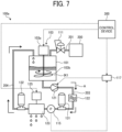
- FIG. 7 is a diagram illustrating a configuration of an ink supply apparatus according to the second embodiment. The configuration of the ink supply apparatus 100a according to the present embodiment will be described with reference to FIG. 7 .
- the accumulator 132 is installed at a position immediately downstream from the discharge head 123 on the ink flow path 204, and is a pressure accumulator that absorbs and compensates for the increase/decrease in the pressure of the ink flowing inside to mitigate the fluctuation in the pressure. That is, the accumulator 132 is installed on the ink flow path 204 at a position downstream from the discharge head 123 and upstream from the pressurizing tank 101, and absorbs the fluctuation of the pressure of the ink flowing through the ink flow path 204.
- the configuration of the accumulator 132 is similar to the configuration of the accumulator 131, and instead of the accumulator 132, the piston pressing mechanism 131-2 (an example of the second mitigation device) illustrated in FIGS. 3A and 3B described above or the subtank 131-3 (an example of the second mitigation device) illustrated in FIGS. 4A and 4B may be used.
- the magnitude of the pressure loss varies depending on the shape, distance, and the like of the flow path in the discharge head 123 to the accumulator 131, and hence the pressure of the ink may vary.
- the discharge head 123 is freely movable in a printable region of the image forming apparatus on which the ink supply apparatus 100a is mounted, and a plurality of nozzles is arranged so as to be as narrow as possible between the nozzles in order to discharge ink at any place in the printable region.
- a damper member for each nozzle, but this is unrealistic in view of the size and configuration layout of the discharge head 123. Therefore, in the present embodiment, as described above, the accumulator 132 is installed at a position immediately downstream from the discharge head 123 on the ink flow path 204. As a result, the damper effect can be more uniformly exhibited for all the nozzles of the discharge head 123, and fluctuations in the pressure and the flow rate due to the discharge of the ink from the discharge head 123 can be more effectively suppressed.
- the accumulator 132 is desirably installed at a position downstream from the discharge head 123 and as close possible to the discharge head 123 in order to reduce the pressure loss in the flow path.
- An ink supply apparatus will be described by focusing on differences from the ink supply apparatus 100 according to the first embodiment.
- a configuration in which another pressurizing tank is provided in addition to the pressurizing tank 101 will be described.
- FIG. 8 is a diagram illustrating a configuration of an ink supply apparatus according to a third embodiment of the present disclosure. A configuration of an ink supply apparatus 100b according to the present embodiment will be described with reference to FIG. 8 .
- the ink supply apparatus 100b includes a high-pressure air supply source 200 (compressed air supply source), a regulator 111 (first regulator), a pressurizing tank 101 (first pressurizing tank), a stirring device 103, a regulator 112 (second regulator), a pressurizing tank 102 (second pressurizing tank), a stirring device 104, a pump 121, a filter 122, a flow meter 140, an accumulator 131 (an example of a first mitigation device), a pressure gauge 115, a discharge head 123, a nozzle open-close control device 125, a pressure flow rate control device 118 (second control device), and a control device 300b.
- a high-pressure air supply source 200 compressed air supply source
- a regulator 111 first regulator
- a pressurizing tank 101 first pressurizing tank
- a stirring device 103 a regulator 112 (second regulator)
- second regulator second regulator
- a pressurizing tank 102 second pressurizing tank
- stirring device 104 a stirring device
- the regulator 111 is a regulator device that is installed on the air supply path 201 and that reduces the pressure of the high-pressure air supplied from the high-pressure air supply source 200 to a given pressure (first pressure). That is, the regulator 111 adjusts the pressure of the air supplied from the air supply path 201 to a given pressure greater than atmospheric pressure and lower than the pressure of the air compressed by the high-pressure air supply source 200, and uses the air at that pressure to pressurize an ink IK1, which is the high-viscosity ink accumulated in the pressurizing tank 101. Adjustment of the pressure reduction by the regulator 111 is controlled by a pressure flow rate control device 118 to be described below.
- the regulator 112 is a regulator device that is installed on an air supply path 202 branched from the air supply path 201, and reduces the pressure of the high-pressure air supplied from the high-pressure air supply source 200 and passing through the regulator 111 to a predetermined pressure (second pressure) that is lower than the first pressure. That is, the regulator 112 adjusts the pressure of the air supplied from the air supply path 201 and passing through the regulator 111 to a given pressure greater than the atmospheric pressure and lower than the pressure of the air decompressed by the regulator 111, and pressurizes the ink IK2, which is the high-viscosity ink with which the pressurizing tank 102 is filled, by means of air at this pressure. Adjustment of the pressure reduction by the regulator 112 is controlled by a pressure flow rate control device 118 to be described below.
- the air supply path 202 on which the regulator 112 is installed is coupled to an upper portion of a pressurizing tank 102 described below.
- the pressurizing tank 102 is a tank filled with the ink IK2, which is a high-viscosity ink.
- the air supply path 202 is coupled to an upper portion of the pressurizing tank 102.
- the compressed air that is sent from the high-pressure air supply source 200 and passes through the regulator 111 and the regulator 112 is supplied into the pressurizing tank 102 to pressurize the ink IK2 in the pressurizing tank 102.
- an ink flow path 205 (an example of a liquid flow path) that enables the ink IK2 to flow out is coupled to a lower portion of the pressurizing tank 102, and the ink flow path 205 is coupled to an upper portion of the pressurizing tank 101.
- the ink flow path 205 which is a "liquid flow path” indicates a flow path through which the ink flowing out from the pressurizing tank 102 flows into the pressurizing tank 101.
- the ink flow path 204 coupled to the discharge hole of the in-head flow path of the discharge head 123 is coupled to the upper portion of the pressurizing tank 102.
- the ink flowing out from the in-head flow path of the discharge head 123 is conveyed to the pressurizing tank 102 through the ink flow path 204.
- the ink accumulated in the pressurizing tank 102 is supplied (conveyed) to the pressurizing tank 101 by the pump 121, and the ink accumulated in the pressurizing tank 101 is conveyed toward the accumulator 131 by the pump 121.
- the "feeder” corresponds to the pressurizing tank 101, the pressurizing tank 102, the regulator 111, the regulator 112, and the pump 121.
- a circulation path is formed in which ink repeatedly circulates in the liquid flow path formed of the ink flow path 203, the ink flow path 204, and the ink flow path 205 in the order of the pressurizing tank 101, the accumulator 131, the discharge head 123, the pressurizing tank 102, and the pressurizing tank 101. Furthermore, a pressure difference is generated between the pressurizing tank 101 and the pressurizing tank 102 by the pressure reduction processing of the regulator 111 and the regulator 112, and the ink is conveyed in the direction indicated by arrow A from the bottom of the pressurizing tank 101 by the pressure difference, the ink circulates in the circulation path, and the ink also passes through the discharge head 123.
- a flow-through state in which the ink flows through the discharge head 123 is implemented.
- the state in which ink continuously flows into the discharge head 123 (the state in which the pressurizing tank 101, the pressurizing tank 102, the regulator 111, and the regulator 112 circulate ink in the circulation path) due to the above-described pressure difference when the discharge head 123 is discharging ink or not discharging ink is referred to as a constant flow-through.
- the pressurizing tank 102 may include, for example, a water level gauge for measuring the fill amount of the ink IK2, an ink temperature controller such as a heater or a cooler for managing the viscosity of the ink IK2, a thermometer for managing and controlling the temperature of the ink IK2, and the like.
- the stirring device 104 is a device for stirring the ink IK2 with which the pressurizing tank 102 is filled.
- the stirring device 104 includes a stirring motor 104a and a stirrer 104b.
- the stirring motor 104a is a motor device for stirring the ink IK2 by rotationally driving the stirrer 104b.
- the on/off operation of the rotation of the stirring motor 104a is controlled by the control device 300b.
- the stirrer 104b is a stirring member that rotates under the rotation of the stirring motor 104a to stir the ink IK2.
- the pump 121 is a pump device that is installed on the ink flow path 205 and that pressure-feeds the ink IK2 in the pressurizing tank 102 in the direction of arrow B of the ink flow path 205.
- the pressurizing tank 102 has the ink in the pressurizing tank 101 continuously flowing therein via the circulation path.
- the ink in the pressurizing tank 101 continues to flow out to the ink flow path 203 due to the air pressurized by the regulator 111, the ink is eventually depleted. Therefore, due to the driving of the pump 121, the ink in the pressurizing tank 102 is continuously or intermittently returned to the pressurizing tank 101 via the ink flow path 205.
- the pump 121 contains a film called a diaphragm, which is an elastic body that separates the ink and the structure, and pressure-feeds the ink through contraction of the diaphragm.
- the speed of rotation of the pump 121 is controlled by the pressure flow rate control device 118.
- the flow meter 140 is a flowmeter which is installed on the downstream side from the filter 122 on the ink flow path 203, and which measures the flow rate of the ink flowing through the ink flow path 203.
- the accumulator 131 is installed on the downstream side from the flow meter 140 on the ink flow path 203.
- the pressure gauge 115 is a pressure gauge that measures the pressure of the ink flowing through the ink flow path 203.
- the pressure gauge 115 is installed at a position downstream from the accumulator 131 and upstream from the discharge head 123 on the ink flow path 203, and measures the pressure obtained by subtracting the pressure loss in each device arranged on the upstream side from the pressure gauge 115 on the ink flow path 203 from the pressure applied to the ink IK1 in the pressurizing tank 101 by the high-pressure air supply source 200. Data on the pressure of the ink measured by the pressure gauge 115 is transmitted to the pressure flow rate control device 118.
- ink supply apparatus 100b illustrated in FIG. 9 in order to measure the pressure after the action of the damper effect by the accumulator 131 with respect to the pressure of the ink on the upstream side from the discharge head 123 in a case where the ink is discharged from the discharge head 123, the arrangement of the pressure gauge 115 and the accumulator 131 is switched around in comparison with the ink supply apparatus 100b illustrated in FIG. 8 .
- the ink is circulated in the circulation path by the pressure difference between the pressurizing tank 101 and the pressurizing tank 102.
- FIGS. 10A to 10D illustrate graphs of the pressure and the flow rate of the ink on the upstream side from the discharge head 123 and the pressure and the flow rate of the ink on the downstream side in cases where the accumulator 131 is installed and not installed, and in a case where the ink is discharged from the discharge head 123 under the conditions of the constant flow-through state and the non-constant flow-through state, respectively.
- the state in which constant flow-through is not performed refers to a state where the ink is not circulated in the circulation path during the discharge period of the discharge head 123 and where the ink is circulated in the circulation path outside the discharge period (hereinafter, referred to as intermittent flow-through).
- 10D illustrates, in chronological order, the pressure value (pressure value measured by the pressure gauge 115) and the flow rate value (flow rate value measured by the flow meter 140) of the ink on the upstream side from the discharge head 123 in a case where the ink is discharged from the discharge head 123 under the condition where the accumulator 131 is not installed and the ink is not in the constant flow-through state (that is, in the intermittent flow state).
- the fluctuation in the pressure value of the ink on the upstream side from the discharge head 123 illustrated in FIG. 10C is smaller than the fluctuation illustrated in FIG.
- the flow rate value of the ink on the upstream side from the discharge head 123 gradually increases, and after the timing at which the discharge ends, gradually decreases without immediately returning to the flow rate value at the time of non-discharge, but it is confirmed to what extent the discharge amount of the ink by the discharge head 123 is affected. This will be described in detail in FIGS. 11A to 12D .
- the fluctuation in the pressure value and the flow rate value of the ink on the upstream side from the discharge head 123 illustrated in FIG. 10B is smaller than the fluctuation illustrated in FIG. 10D , and it is understood that the fluctuation in the pressure and the flow rate on the upstream side due to the discharge of the ink of the discharge head 123 is suppressed in the constant flow-through state.
- the fluctuation in the pressure value of the ink on the upstream side and the downstream side from the discharge head 123 illustrated in FIG. 11A is smaller than the fluctuation illustrated in FIG. 11B , and it is understood that the fluctuation in the pressure due to the discharge of the ink of the discharge head 123 is suppressed by the accumulator 131.
- the fluctuation of the flow rate value of the ink on the downstream side from the discharge head 123 illustrated in FIG. 11A is smaller than the fluctuation illustrated in FIG. 11B , and it is understood that the fluctuation of the flow rate on the downstream side due to the discharge of the ink of the discharge head 123 is suppressed by the accumulator 131.
- the fluctuation in the pressure value of the ink on the upstream side from the discharge head 123 illustrated in FIG. 11C is smaller than the fluctuation illustrated in FIG. 11D , and it is understood that the fluctuation in the pressure on the upstream side due to the discharge of the ink of the discharge head 123 is suppressed by the accumulator 131.
- the ink used by the ink supply apparatus 100b absorbs the energy which becomes a factor in the changes in pressure and flow rate. This phenomenon is considered to be because the ink is a high-viscosity fluid, and thus acts similarly to a brake with respect to the changes in pressure and flow rate, and absorbs the energy of the fluctuations in pressure and flow rate upon receiving a shear force exhibiting thixotropy and thus likewise acts similarly to a brake.
- the accumulator 131 is provided and the ink is in the constant flow-through state, the effect of suppressing the fluctuations in the pressure and the flow rate of the ink and the stability of the discharge amount with respect to the steep pressure fluctuation due to the discharge of the ink from the discharge head 123 is exhibited not only in the ink supply apparatus 100b according to the present embodiment, but also in the ink supply apparatuses 100 and 100a according to the first embodiment and the second embodiment, respectively.
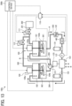
- FIG. 13 is a diagram illustrating a configuration of an ink supply apparatus according to a fourth embodiment of the present disclosure. A configuration of an ink supply apparatus 100c according to the present embodiment will be described with reference to FIG. 13 .
- the ink supply apparatus 100c includes a high-pressure air supply source 200 (compressed air supply source), a regulator 111 (first regulator), a pressurizing tank 101 (first pressurizing tank), a stirring device 103, a regulator 112 (second regulator), a pressurizing tank 102 (second pressurizing tank), a stirring device 104, a pump 121, a filter 122, a flow meter 140, an accumulator 131 (an example of a first mitigation device), a pressure gauge 115, a discharge head 123, a nozzle open-close control device 125, an accumulator 132 (an example of a second mitigation device), a pressure flow rate control device 118 (second control device), and a control device 300b. That is, the configuration of the ink supply apparatus 100c is similar to the configuration of the ink supply apparatus 100b according to the third embodiment described above except that the accumulator 132 is provided.
- the accumulator 132 is installed at a position immediately downstream from the discharge head 123 on the ink flow path 204, and is a pressure accumulator that absorbs and compensates for the increase/decrease in the pressure of the ink flowing inside to mitigate the fluctuation in the pressure.
- the configuration of the accumulator 132 is similar to the configuration of the accumulator 131, and instead of the accumulator 132, the piston pressing mechanism 131-2 (an example of the second mitigation device) illustrated in FIGS. 3A and 3B described above or the subtank 131-3 (an example of the second mitigation device) illustrated in FIGS. 4A and 4B may be used.
- the damper effect can be more uniformly exhibited for all the nozzles of the discharge head 123, and fluctuations in the pressure and the flow rate due to the discharge of the ink from the discharge head 123 can be more effectively suppressed.
- the accumulator 132 is desirably installed at a position downstream from the discharge head 123 and as close possible to the discharge head 123 in order to reduce the pressure loss in the flow path.
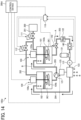
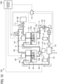
- FIG. 14 is a diagram illustrating a configuration of an ink supply apparatus according to a fifth embodiment of the present disclosure. A configuration of an ink supply apparatus 100d according to the present embodiment will be described with reference to FIG. 14 .
- the flow rate control valve 142 is installed on the ink flow path 203 at a position downstream from the pressurizing tank 101 and upstream from the accumulator 131, and is a valve device that controls the flow rate of the ink flowing out from the pressurizing tank 101 to the ink flow path 203.
- the opening degree of the flow rate control valve 142 is controlled by the pressure flow rate control device 118.
- the pressure flow rate control device 118 is a device that receives data on the pressure of the ink measured by the pressure gauge 115 and that controls the pressure reduction operation by the regulator 111 and the regulator 112 so that the pressure becomes a given pressure. Furthermore, the pressure flow rate control device 118 performs stable pressure control of the ink by controlling the pressure reduction operation by the regulator 111 and the regulator 112 on the basis of the data on the pressure (discharge pressure) of the ink measured by the pressure gauge 115 when the nozzle of the discharge head 123 is not open, in conjunction with the nozzle open-close control device 125. In this case, the pressure flow rate control device 118 detects the open state of the nozzles of the nozzle open-close control device 125 via the control device 300d.
- the pressure flow rate control device 118 is installed on the ink flow path 203 at a position downstream from the pressurizing tank 101 and upstream from the discharge head 123, and receives data on the flow rate of the ink measured by the flow meter 140, and, on the basis of the data, performs control of the drive time and the speed of rotation of the pump 121 and control of the opening degree of the flow rate control valve 142.
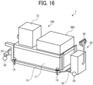
- the main scanning motor 17a is a motor for reciprocating the carriage 16 in the main scanning direction along the main scanning guide 17.
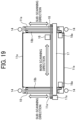
- the sub-scanning guides 18 are guide members that are installed on the frames 11a each extending in the sub-scanning direction illustrated in FIG. 19 and support the main scanning guide 17 to be slidable in the sub-scanning direction. As illustrated in FIG. 19 , the sub-scanning guides 18 are disposed on two frames 11a each extending in the sub-scanning direction and facing each other such that the sub-scanning guides 18 support the vicinities of both ends of the main scanning guide 17 extending in the main scanning direction.
- the sub-scanning motors 18a are motors for reciprocating the main scanning guide 17 in the sub-scanning direction along the sub-scanning guides 18.
- the sub-scanning motors 18a are rotated to drive pulleys, which are rotated by the sub-scanning motors 18a, and the timing belts 18b wound around the pulleys rotated by the sub-scanning motors 18a.
- the main scanning guide 17 reciprocates in the sub-scanning direction.
Landscapes
- Ink Jet (AREA)
Claims (13)
- Flüssigkeitszufuhrvorrichtung (100), umfassend:eine Druckluftversorgungsquelle (200) zum Verdichten von Luft;einen Druckbehälter (101, 102), der von der Druckluftversorgungsquelle (200) mit der Druckluft versorgt wird und die durch die Druckluft unter Druck gesetzte Flüssigkeit speichert;eine Zuführung (121), um die im Druckbehälter (101, 102) angesammelte Flüssigkeit einem Flüssigkeitsdurchflussweg (203, 204, 205) zuzuführen;einen Ausstoßkopf (123), der einen inneren Strömungsweg enthält, durch den die vom Flüssigkeitsströmungsweg (203, 204, 205) zugeführte Flüssigkeit strömt, wobei der Ausstoßkopf (123) eine Düse zum Ausstoßen der Flüssigkeit aus dem inneren Strömungsweg aufweist;eine Abschwächungsvorrichtung (131, 131-2, 131-3), die in dem Flüssigkeitsströmungsweg (203, 204, 205) an einer Position stromabwärts von dem Druckbehälter (101, 102) und stromaufwärts von dem Auslasskopf (123) installiert ist, wobei die Abschwächungsvorrichtung (131, 131-2, 131-3) eine Druckschwankung der durch den Flüssigkeitsströmungsweg (203, 204, 205) strömenden Flüssigkeit absorbiert, wobei die Abschwächungsvorrichtung ein Kolbendruckmechanismus ist, der einen Akkumulator, einen Untertank oder einen Stoßdämpfer umfasst; undeinen Zirkulationspfad, in dem die Zuführung die Flüssigkeit im Flüssigkeitsströmungspfad (203, 204, 205) in der Reihenfolge des Druckbehälters (101, 102), der Minderungsvorrichtung, des Auslasskopfes (123) und des Druckbehälters (101, 102) zirkulieren lässt,dadurch gekennzeichnet, dassdie Zuführung eine Pumpe (121) ist, die in dem Flüssigkeitsströmungsweg (203, 204, 205) an einer Position stromabwärts von dem Druckbehälter (101, 102) und stromaufwärts von der Abschwächungsvorrichtung installiert ist, um die Flüssigkeit in dem Druckbehälter (101, 102) in Richtung der Abschwächungsvorrichtung und zu dem Flüssigkeitsströmungsweg (203, 204, 205) unter Druck zu fördern.
- Flüssigkeitszufuhrvorrichtung nach Anspruch 1,
wobei die Zuführung (121) die Flüssigkeit im Zirkulationsweg zirkulieren lässt, sowohl wenn der Auslasskopf (123) die Flüssigkeit ausstößt als auch wenn der Auslasskopf (123) die Flüssigkeit nicht ausstößt. - Flüssigkeitszufuhrvorrichtung nach Anspruch 1, ferner umfassend:ein Druckmessgerät (115, 116), das in dem Flüssigkeitsströmungsweg (203, 204, 205) an einer Position stromabwärts von der Minderungsvorrichtung und stromaufwärts von dem Auslasskopf (123) installiert ist, um den Druck der durch den Flüssigkeitsströmungsweg (203, 204, 205) strömenden Flüssigkeit zu messen; undeine Steuervorrichtung (117) zur Steuerung der Drehgeschwindigkeit der Pumpe (121), so dass ein von dem Druckmesser (115, 116) gemessener Druck einen vorbestimmten Wert erreicht.
- Flüssigkeitszufuhrvorrichtung nach Anspruch 1 oder 2,
wobei der Druckbehälter (101, 102) einen ersten Druckbehälter (101), aus dem die angesammelte Flüssigkeit durch die Zuführung in Richtung der Minderungsvorrichtung zugeführt wird, und einen zweiten Druckbehälter (102), aus dem die angesammelte Flüssigkeit dem ersten Druckbehälter zugeführt wird, umfasst. - Flüssigkeitszufuhrvorrichtung nach Anspruch 4, ferner umfassend:einen ersten Regler (111) zum Reduzieren eines Drucks der von der Druckluftversorgungsquelle zum ersten Druckbehälter gelieferten Druckluft auf einen ersten Druck;einen zweiten Regler (112) zum Reduzieren eines Drucks der von der Druckluftversorgungsquelle zu dem zweiten Druckbehälter gelieferten Druckluft auf einen zweiten Druck, der kleiner als der erste Druck ist; undeine Pumpe (121) zur Förderung der im zweiten Druckbehälter angesammelten Flüssigkeit zum ersten Druckbehälter.
- Flüssigkeitszufuhrvorrichtung nach Anspruch 5,wobei die aus dem inneren Strömungsweg des Auslasskopfes (123) ausfließende Flüssigkeit über den Flüssigkeitsströmungsweg (203, 204, 205) zu dem zweiten Druckbehälter befördert wird, undwobei der Zuführer den ersten Druckbehälter, den zweiten Druckbehälter, den ersten Regler (111), den zweiten Regler (112) und die Pumpe (121) umfasst, um die im ersten Druckbehälter angesammelte Flüssigkeit dem Flüssigkeitsströmungsweg (203, 204, 205) zuzuführen.
- Flüssigkeitszufuhrvorrichtung nach Anspruch 5 oder 6, ferner umfassend:ein Druckmessgerät (115, 116), das in dem Flüssigkeitsströmungsweg (203, 204, 205) an einer Position stromabwärts von der Minderungsvorrichtung und stromaufwärts von dem Auslasskopf (123) installiert ist, um den Druck der durch den Flüssigkeitsströmungsweg (203, 204, 205) strömenden Flüssigkeit zu messen; undeine Steuervorrichtung (118) zum Steuern eines Druckreduzierungsvorgangs durch den ersten Regler (111) und den zweiten Regler (112), so dass der durch das Druckmessgerät (115, 116) gemessene Druck ein vorbestimmter Wert ist.
- Flüssigkeitszufuhrvorrichtung nach einem der Ansprüche 4 bis 6, die ferner ein Durchflussmengenregelventil (142) umfasst, das in dem Flüssigkeitsdurchflussweg (203, 204, 205) an einer Position stromabwärts von dem ersten Druckbehälter und stromaufwärts von der Abschwächungsvorrichtung installiert ist, um die Durchflussmenge der Flüssigkeit in dem Flüssigkeitsdurchflussweg (203, 204, 205) zu regeln.
- Die Flüssigkeitszufuhrvorrichtung nach Anspruch 8, ferner umfassend:einen Durchflussmesser, der in dem Flüssigkeitsdurchflussweg (203, 204, 205) an einer Position stromabwärts von dem ersten Druckbehälter und stromaufwärts von dem Auslasskopf (123) installiert ist, um die Durchflussrate der durch den Flüssigkeitsdurchflussweg (203, 204, 205) fließenden Flüssigkeit zu messen; undeine Steuervorrichtung (118) zur Steuerung eines Öffnungsgrades des Durchflussregelventils (142) auf der Grundlage des vom Durchflussmesser gemessenen Durchflusses.
- Flüssigkeitsversorgungsvorrichtung nach einem der Ansprüche 1 bis 9, die ferner eine weitere Abschwächungsvorrichtung (132, 131-2, 131-3) umfasst, die in dem Flüssigkeitsstrompfad (203, 204, 205) an einer Position stromabwärts des Auslasskopfes (123) und stromaufwärts des Druckbehälters installiert ist, um die Druckschwankung der durch den Flüssigkeitsstrompfad (203, 204, 205) strömenden Flüssigkeit zu absorbieren.
- Flüssigkeitszufuhrvorrichtung nach einem der Ansprüche 1 bis 10,
wobei der Ausstoßkopf (123) ein Tintenstrahlkopf zum Betätigen einer Nadel unter Verwendung eines Aktuators zum Öffnen und Schließen der Düse ist. - Flüssigkeitszufuhrvorrichtung nach einem der Ansprüche 1 bis 11,
wobei der Druckbehälter (101, 102) mit Luft versorgt wird, die von der Druckluftversorungsquelle auf einen Druck gleich oder größer als der Atmosphärendruck komprimiert wird. - Vorrichtung zum Auftragen von Flüssigkeiten (1), umfassend:die Flüssigkeitszufuhrvorrichtung (100) nach einem der vorhergehenden Ansprüche, um Flüssigkeit auf eine Installationsfläche abzugeben;eine Transportvorrichtung (20) zum Bewegen der Flüssigkeitszufuhrvorrichtung; undeine Stütze (14) zum Tragen der Flüssigkeitszufuhrvorrichtung.
Applications Claiming Priority (2)
| Application Number | Priority Date | Filing Date | Title |
|---|---|---|---|
| JP2022211980 | 2022-12-28 | ||
| JP2023189683A JP2024095534A (ja) | 2022-12-28 | 2023-11-06 | 液体供給装置および液体塗布装置 |
Publications (2)
| Publication Number | Publication Date |
|---|---|
| EP4393715A1 EP4393715A1 (de) | 2024-07-03 |
| EP4393715B1 true EP4393715B1 (de) | 2025-07-09 |
Family
ID=89224189
Family Applications (1)
| Application Number | Title | Priority Date | Filing Date |
|---|---|---|---|
| EP23218124.8A Active EP4393715B1 (de) | 2022-12-28 | 2023-12-19 | Flüssigkeitsversorgungsvorrichtung und flüssigkeitsauftragsvorrichtung |
Country Status (1)
| Country | Link |
|---|---|
| EP (1) | EP4393715B1 (de) |
Family Cites Families (4)
| Publication number | Priority date | Publication date | Assignee | Title |
|---|---|---|---|---|
| FR2652540B1 (fr) * | 1989-10-02 | 1995-06-02 | Imaje Sa | Circuit d'encre notamment destine a la mise en pression d'une encre a pigments pour imprimante a jet d'encre. |
| JP4123897B2 (ja) | 2002-10-28 | 2008-07-23 | 株式会社エルエーシー | インクジェットノズル |
| WO2006075314A2 (en) * | 2005-01-11 | 2006-07-20 | Jemtex Ink Jet Printing Ltd. | Inkjet printer and method of controlling same |
| JP7463758B2 (ja) | 2019-03-29 | 2024-04-09 | ブラザー工業株式会社 | 液体吐出装置及び液体吐出装置の制御方法 |
-
2023
- 2023-12-19 EP EP23218124.8A patent/EP4393715B1/de active Active
Also Published As
| Publication number | Publication date |
|---|---|
| US20240217244A1 (en) | 2024-07-04 |
| EP4393715A1 (de) | 2024-07-03 |
Similar Documents
| Publication | Publication Date | Title |
|---|---|---|
| KR101435554B1 (ko) | 액체 순환 시스템 | |
| JP5040039B2 (ja) | インク供給システム | |
| JP5084610B2 (ja) | 印刷装置および印刷方法 | |
| KR20120069777A (ko) | 액체 순환 시스템 | |
| US10569562B2 (en) | Liquid ejecting apparatus and control method of liquid ejecting apparatus | |
| US8708453B2 (en) | Cleaning method and fluid ejecting apparatus | |
| US11807010B2 (en) | Liquid ejecting apparatus and maintenance method of liquid ejecting apparatus | |
| US20120194620A1 (en) | Liquid ejecting apparatus | |
| US9409404B2 (en) | Liquid ejection head and liquid ejection apparatus | |
| CN107813606A (zh) | 液体循环装置、液体喷吐装置以及液体喷吐方法 | |
| JP2019051613A (ja) | 液体吐出装置および液体吐出装置の制御方法 | |
| JP6571725B2 (ja) | ダイヤフラムポンプ、インク供給システム、およびインクジェットプリンタ | |
| US11491793B2 (en) | Liquid ejecting apparatus and maintenance method for liquid ejecting apparatus | |
| JP2018099791A (ja) | インク供給システムおよびインクジェットプリンタ | |
| EP4393715B1 (de) | Flüssigkeitsversorgungsvorrichtung und flüssigkeitsauftragsvorrichtung | |
| US12617213B2 (en) | Liquid supply apparatus and liquid application apparatus | |
| US11858266B2 (en) | Liquid ejecting apparatus and maintenance method of liquid ejecting apparatus | |
| CN114103444B (zh) | 液体喷射装置、液体喷射装置的维护方法 | |
| KR20210038902A (ko) | 인쇄 모듈을 위한 잉크 전달 시스템 및 잉크 전달 방법 | |
| EP2316654A1 (de) | Flüssigkeitsausstosskopf, wageneinheit, drucksteuerungsverrfahren und flüssgkeitsausstoss-aufzeichnungsvorrichtung | |
| US8197023B2 (en) | Liquid jet recording apparatus and liquid jet recording method | |
| JP2024095534A (ja) | 液体供給装置および液体塗布装置 | |
| WO2010024085A1 (ja) | 液体噴射記録装置及び液体噴射記録方法 | |
| JP2010179225A (ja) | 塗布装置 | |
| CN118254479A (zh) | 液体供给装置及液体涂敷装置 |
Legal Events
| Date | Code | Title | Description |
|---|---|---|---|
| PUAI | Public reference made under article 153(3) epc to a published international application that has entered the european phase |
Free format text: ORIGINAL CODE: 0009012 |
|
| STAA | Information on the status of an ep patent application or granted ep patent |
Free format text: STATUS: REQUEST FOR EXAMINATION WAS MADE |
|
| 17P | Request for examination filed |
Effective date: 20231219 |
|
| AK | Designated contracting states |
Kind code of ref document: A1 Designated state(s): AL AT BE BG CH CY CZ DE DK EE ES FI FR GB GR HR HU IE IS IT LI LT LU LV MC ME MK MT NL NO PL PT RO RS SE SI SK SM TR |
|
| GRAP | Despatch of communication of intention to grant a patent |
Free format text: ORIGINAL CODE: EPIDOSNIGR1 |
|
| STAA | Information on the status of an ep patent application or granted ep patent |
Free format text: STATUS: GRANT OF PATENT IS INTENDED |
|
| INTG | Intention to grant announced |
Effective date: 20250310 |
|
| P01 | Opt-out of the competence of the unified patent court (upc) registered |
Free format text: CASE NUMBER: APP_18793/2025 Effective date: 20250417 |
|
| GRAS | Grant fee paid |
Free format text: ORIGINAL CODE: EPIDOSNIGR3 |
|
| GRAA | (expected) grant |
Free format text: ORIGINAL CODE: 0009210 |
|
| STAA | Information on the status of an ep patent application or granted ep patent |
Free format text: STATUS: THE PATENT HAS BEEN GRANTED |
|
| AK | Designated contracting states |
Kind code of ref document: B1 Designated state(s): AL AT BE BG CH CY CZ DE DK EE ES FI FR GB GR HR HU IE IS IT LI LT LU LV MC ME MK MT NL NO PL PT RO RS SE SI SK SM TR |
|
| REG | Reference to a national code |
Ref country code: GB Ref legal event code: FG4D |
|
| REG | Reference to a national code |
Ref country code: CH Ref legal event code: EP |
|
| REG | Reference to a national code |
Ref country code: IE Ref legal event code: FG4D |
|
| REG | Reference to a national code |
Ref country code: DE Ref legal event code: R096 Ref document number: 602023004715 Country of ref document: DE |
|
| REG | Reference to a national code |
Ref country code: NL Ref legal event code: MP Effective date: 20250709 |
|
| PG25 | Lapsed in a contracting state [announced via postgrant information from national office to epo] |
Ref country code: PT Free format text: LAPSE BECAUSE OF FAILURE TO SUBMIT A TRANSLATION OF THE DESCRIPTION OR TO PAY THE FEE WITHIN THE PRESCRIBED TIME-LIMIT Effective date: 20251110 |
|
| PG25 | Lapsed in a contracting state [announced via postgrant information from national office to epo] |
Ref country code: NL Free format text: LAPSE BECAUSE OF FAILURE TO SUBMIT A TRANSLATION OF THE DESCRIPTION OR TO PAY THE FEE WITHIN THE PRESCRIBED TIME-LIMIT Effective date: 20250709 |
|
| REG | Reference to a national code |
Ref country code: AT Ref legal event code: MK05 Ref document number: 1811523 Country of ref document: AT Kind code of ref document: T Effective date: 20250709 |
|
| PG25 | Lapsed in a contracting state [announced via postgrant information from national office to epo] |
Ref country code: IS Free format text: LAPSE BECAUSE OF FAILURE TO SUBMIT A TRANSLATION OF THE DESCRIPTION OR TO PAY THE FEE WITHIN THE PRESCRIBED TIME-LIMIT Effective date: 20251109 |
|
| PGFP | Annual fee paid to national office [announced via postgrant information from national office to epo] |
Ref country code: DE Payment date: 20251211 Year of fee payment: 3 |
|
| PG25 | Lapsed in a contracting state [announced via postgrant information from national office to epo] |
Ref country code: NO Free format text: LAPSE BECAUSE OF FAILURE TO SUBMIT A TRANSLATION OF THE DESCRIPTION OR TO PAY THE FEE WITHIN THE PRESCRIBED TIME-LIMIT Effective date: 20251009 |
|
| REG | Reference to a national code |
Ref country code: LT Ref legal event code: MG9D |
|
| PG25 | Lapsed in a contracting state [announced via postgrant information from national office to epo] |
Ref country code: AT Free format text: LAPSE BECAUSE OF FAILURE TO SUBMIT A TRANSLATION OF THE DESCRIPTION OR TO PAY THE FEE WITHIN THE PRESCRIBED TIME-LIMIT Effective date: 20250709 |
|
| PG25 | Lapsed in a contracting state [announced via postgrant information from national office to epo] |
Ref country code: FI Free format text: LAPSE BECAUSE OF FAILURE TO SUBMIT A TRANSLATION OF THE DESCRIPTION OR TO PAY THE FEE WITHIN THE PRESCRIBED TIME-LIMIT Effective date: 20250709 |
|
| PG25 | Lapsed in a contracting state [announced via postgrant information from national office to epo] |
Ref country code: HR Free format text: LAPSE BECAUSE OF FAILURE TO SUBMIT A TRANSLATION OF THE DESCRIPTION OR TO PAY THE FEE WITHIN THE PRESCRIBED TIME-LIMIT Effective date: 20250709 |
|
| PGFP | Annual fee paid to national office [announced via postgrant information from national office to epo] |
Ref country code: FR Payment date: 20251229 Year of fee payment: 3 |
|
| PG25 | Lapsed in a contracting state [announced via postgrant information from national office to epo] |
Ref country code: GR Free format text: LAPSE BECAUSE OF FAILURE TO SUBMIT A TRANSLATION OF THE DESCRIPTION OR TO PAY THE FEE WITHIN THE PRESCRIBED TIME-LIMIT Effective date: 20251010 |
|
| PG25 | Lapsed in a contracting state [announced via postgrant information from national office to epo] |
Ref country code: SE Free format text: LAPSE BECAUSE OF FAILURE TO SUBMIT A TRANSLATION OF THE DESCRIPTION OR TO PAY THE FEE WITHIN THE PRESCRIBED TIME-LIMIT Effective date: 20250709 |
|
| PG25 | Lapsed in a contracting state [announced via postgrant information from national office to epo] |
Ref country code: LV Free format text: LAPSE BECAUSE OF FAILURE TO SUBMIT A TRANSLATION OF THE DESCRIPTION OR TO PAY THE FEE WITHIN THE PRESCRIBED TIME-LIMIT Effective date: 20250709 |
|
| PG25 | Lapsed in a contracting state [announced via postgrant information from national office to epo] |
Ref country code: PL Free format text: LAPSE BECAUSE OF FAILURE TO SUBMIT A TRANSLATION OF THE DESCRIPTION OR TO PAY THE FEE WITHIN THE PRESCRIBED TIME-LIMIT Effective date: 20250709 Ref country code: BG Free format text: LAPSE BECAUSE OF FAILURE TO SUBMIT A TRANSLATION OF THE DESCRIPTION OR TO PAY THE FEE WITHIN THE PRESCRIBED TIME-LIMIT Effective date: 20250709 |
|
| PG25 | Lapsed in a contracting state [announced via postgrant information from national office to epo] |
Ref country code: RS Free format text: LAPSE BECAUSE OF FAILURE TO SUBMIT A TRANSLATION OF THE DESCRIPTION OR TO PAY THE FEE WITHIN THE PRESCRIBED TIME-LIMIT Effective date: 20251009 |
|
| PG25 | Lapsed in a contracting state [announced via postgrant information from national office to epo] |
Ref country code: ES Free format text: LAPSE BECAUSE OF FAILURE TO SUBMIT A TRANSLATION OF THE DESCRIPTION OR TO PAY THE FEE WITHIN THE PRESCRIBED TIME-LIMIT Effective date: 20250709 |
|
| PG25 | Lapsed in a contracting state [announced via postgrant information from national office to epo] |
Ref country code: RO Free format text: LAPSE BECAUSE OF FAILURE TO SUBMIT A TRANSLATION OF THE DESCRIPTION OR TO PAY THE FEE WITHIN THE PRESCRIBED TIME-LIMIT Effective date: 20250709 |
|
| PG25 | Lapsed in a contracting state [announced via postgrant information from national office to epo] |
Ref country code: SM Free format text: LAPSE BECAUSE OF FAILURE TO SUBMIT A TRANSLATION OF THE DESCRIPTION OR TO PAY THE FEE WITHIN THE PRESCRIBED TIME-LIMIT Effective date: 20250709 |
|
| PG25 | Lapsed in a contracting state [announced via postgrant information from national office to epo] |
Ref country code: DK Free format text: LAPSE BECAUSE OF FAILURE TO SUBMIT A TRANSLATION OF THE DESCRIPTION OR TO PAY THE FEE WITHIN THE PRESCRIBED TIME-LIMIT Effective date: 20250709 |
|
| PG25 | Lapsed in a contracting state [announced via postgrant information from national office to epo] |
Ref country code: IT Free format text: LAPSE BECAUSE OF FAILURE TO SUBMIT A TRANSLATION OF THE DESCRIPTION OR TO PAY THE FEE WITHIN THE PRESCRIBED TIME-LIMIT Effective date: 20250709 |
|
| PG25 | Lapsed in a contracting state [announced via postgrant information from national office to epo] |
Ref country code: CZ Free format text: LAPSE BECAUSE OF FAILURE TO SUBMIT A TRANSLATION OF THE DESCRIPTION OR TO PAY THE FEE WITHIN THE PRESCRIBED TIME-LIMIT Effective date: 20250709 |
|
| PG25 | Lapsed in a contracting state [announced via postgrant information from national office to epo] |
Ref country code: SK Free format text: LAPSE BECAUSE OF FAILURE TO SUBMIT A TRANSLATION OF THE DESCRIPTION OR TO PAY THE FEE WITHIN THE PRESCRIBED TIME-LIMIT Effective date: 20250709 Ref country code: EE Free format text: LAPSE BECAUSE OF FAILURE TO SUBMIT A TRANSLATION OF THE DESCRIPTION OR TO PAY THE FEE WITHIN THE PRESCRIBED TIME-LIMIT Effective date: 20250709 |