EP4393719A2 - Imprimante à transfert et procédé associé - Google Patents
Imprimante à transfert et procédé associé Download PDFInfo
- Publication number
- EP4393719A2 EP4393719A2 EP24172482.2A EP24172482A EP4393719A2 EP 4393719 A2 EP4393719 A2 EP 4393719A2 EP 24172482 A EP24172482 A EP 24172482A EP 4393719 A2 EP4393719 A2 EP 4393719A2
- Authority
- EP
- European Patent Office
- Prior art keywords
- ribbon
- printhead
- image
- printing
- characteristic
- Prior art date
- Legal status (The legal status is an assumption and is not a legal conclusion. Google has not performed a legal analysis and makes no representation as to the accuracy of the status listed.)
- Pending
Links
Images







Classifications
-
- B—PERFORMING OPERATIONS; TRANSPORTING
- B41—PRINTING; LINING MACHINES; TYPEWRITERS; STAMPS
- B41J—TYPEWRITERS; SELECTIVE PRINTING MECHANISMS, i.e. MECHANISMS PRINTING OTHERWISE THAN FROM A FORME; CORRECTION OF TYPOGRAPHICAL ERRORS
- B41J2/00—Typewriters or selective printing mechanisms characterised by the printing or marking process for which they are designed
- B41J2/315—Typewriters or selective printing mechanisms characterised by the printing or marking process for which they are designed characterised by selective application of heat to a heat sensitive printing or impression-transfer material
- B41J2/32—Typewriters or selective printing mechanisms characterised by the printing or marking process for which they are designed characterised by selective application of heat to a heat sensitive printing or impression-transfer material using thermal heads
- B41J2/325—Typewriters or selective printing mechanisms characterised by the printing or marking process for which they are designed characterised by selective application of heat to a heat sensitive printing or impression-transfer material using thermal heads by selective transfer of ink from ink carrier, e.g. from ink ribbon or sheet
-
- B—PERFORMING OPERATIONS; TRANSPORTING
- B41—PRINTING; LINING MACHINES; TYPEWRITERS; STAMPS
- B41J—TYPEWRITERS; SELECTIVE PRINTING MECHANISMS, i.e. MECHANISMS PRINTING OTHERWISE THAN FROM A FORME; CORRECTION OF TYPOGRAPHICAL ERRORS
- B41J29/00—Details of, or accessories for, typewriters or selective printing mechanisms not otherwise provided for
- B41J29/38—Drives, motors, controls or automatic cut-off devices for the entire printing mechanism
- B41J29/393—Devices for controlling or analysing the entire machine ; Controlling or analysing mechanical parameters involving printing of test patterns
-
- B—PERFORMING OPERATIONS; TRANSPORTING
- B41—PRINTING; LINING MACHINES; TYPEWRITERS; STAMPS
- B41F—PRINTING MACHINES OR PRESSES
- B41F16/00—Transfer printing apparatus
- B41F16/0006—Transfer printing apparatus for printing from an inked or preprinted foil or band
- B41F16/002—Presses of the rotary type
- B41F16/0026—Presses of the rotary type with means for applying print under heat and pressure, e.g. using heat activable adhesive
-
- B—PERFORMING OPERATIONS; TRANSPORTING
- B41—PRINTING; LINING MACHINES; TYPEWRITERS; STAMPS
- B41J—TYPEWRITERS; SELECTIVE PRINTING MECHANISMS, i.e. MECHANISMS PRINTING OTHERWISE THAN FROM A FORME; CORRECTION OF TYPOGRAPHICAL ERRORS
- B41J17/00—Mechanisms for manipulating page-width impression-transfer material, e.g. carbon paper
- B41J17/02—Feeding mechanisms
-
- B—PERFORMING OPERATIONS; TRANSPORTING
- B41—PRINTING; LINING MACHINES; TYPEWRITERS; STAMPS
- B41J—TYPEWRITERS; SELECTIVE PRINTING MECHANISMS, i.e. MECHANISMS PRINTING OTHERWISE THAN FROM A FORME; CORRECTION OF TYPOGRAPHICAL ERRORS
- B41J17/00—Mechanisms for manipulating page-width impression-transfer material, e.g. carbon paper
- B41J17/02—Feeding mechanisms
- B41J17/04—Feed dependent on the record-paper feed, e.g. both moved at the same time
- B41J17/07—Feed dependent on the record-paper feed, e.g. both moved at the same time electromagnetically controlled
-
- B—PERFORMING OPERATIONS; TRANSPORTING
- B41—PRINTING; LINING MACHINES; TYPEWRITERS; STAMPS
- B41J—TYPEWRITERS; SELECTIVE PRINTING MECHANISMS, i.e. MECHANISMS PRINTING OTHERWISE THAN FROM A FORME; CORRECTION OF TYPOGRAPHICAL ERRORS
- B41J17/00—Mechanisms for manipulating page-width impression-transfer material, e.g. carbon paper
- B41J17/02—Feeding mechanisms
- B41J17/08—Feed independent of the record-paper feed
- B41J17/10—Feed independent of the record-paper feed electromagnetically controlled
-
- B—PERFORMING OPERATIONS; TRANSPORTING
- B41—PRINTING; LINING MACHINES; TYPEWRITERS; STAMPS
- B41J—TYPEWRITERS; SELECTIVE PRINTING MECHANISMS, i.e. MECHANISMS PRINTING OTHERWISE THAN FROM A FORME; CORRECTION OF TYPOGRAPHICAL ERRORS
- B41J17/00—Mechanisms for manipulating page-width impression-transfer material, e.g. carbon paper
- B41J17/36—Alarms, indicators, or feed-disabling devices responsible to material breakage or exhaustion
-
- B—PERFORMING OPERATIONS; TRANSPORTING
- B41—PRINTING; LINING MACHINES; TYPEWRITERS; STAMPS
- B41J—TYPEWRITERS; SELECTIVE PRINTING MECHANISMS, i.e. MECHANISMS PRINTING OTHERWISE THAN FROM A FORME; CORRECTION OF TYPOGRAPHICAL ERRORS
- B41J2/00—Typewriters or selective printing mechanisms characterised by the printing or marking process for which they are designed
- B41J2/315—Typewriters or selective printing mechanisms characterised by the printing or marking process for which they are designed characterised by selective application of heat to a heat sensitive printing or impression-transfer material
- B41J2/32—Typewriters or selective printing mechanisms characterised by the printing or marking process for which they are designed characterised by selective application of heat to a heat sensitive printing or impression-transfer material using thermal heads
-
- B—PERFORMING OPERATIONS; TRANSPORTING
- B41—PRINTING; LINING MACHINES; TYPEWRITERS; STAMPS
- B41J—TYPEWRITERS; SELECTIVE PRINTING MECHANISMS, i.e. MECHANISMS PRINTING OTHERWISE THAN FROM A FORME; CORRECTION OF TYPOGRAPHICAL ERRORS
- B41J2/00—Typewriters or selective printing mechanisms characterised by the printing or marking process for which they are designed
- B41J2/315—Typewriters or selective printing mechanisms characterised by the printing or marking process for which they are designed characterised by selective application of heat to a heat sensitive printing or impression-transfer material
- B41J2/32—Typewriters or selective printing mechanisms characterised by the printing or marking process for which they are designed characterised by selective application of heat to a heat sensitive printing or impression-transfer material using thermal heads
- B41J2/35—Typewriters or selective printing mechanisms characterised by the printing or marking process for which they are designed characterised by selective application of heat to a heat sensitive printing or impression-transfer material using thermal heads providing current or voltage to the thermal head
- B41J2/355—Control circuits for heating-element selection
- B41J2/36—Print density control
-
- B—PERFORMING OPERATIONS; TRANSPORTING
- B41—PRINTING; LINING MACHINES; TYPEWRITERS; STAMPS
- B41J—TYPEWRITERS; SELECTIVE PRINTING MECHANISMS, i.e. MECHANISMS PRINTING OTHERWISE THAN FROM A FORME; CORRECTION OF TYPOGRAPHICAL ERRORS
- B41J33/00—Apparatus or arrangements for feeding ink ribbons or like character-size impression-transfer material
- B41J33/14—Ribbon-feed devices or mechanisms
- B41J33/16—Ribbon-feed devices or mechanisms with drive applied to spool or spool spindle
-
- B—PERFORMING OPERATIONS; TRANSPORTING
- B41—PRINTING; LINING MACHINES; TYPEWRITERS; STAMPS
- B41J—TYPEWRITERS; SELECTIVE PRINTING MECHANISMS, i.e. MECHANISMS PRINTING OTHERWISE THAN FROM A FORME; CORRECTION OF TYPOGRAPHICAL ERRORS
- B41J33/00—Apparatus or arrangements for feeding ink ribbons or like character-size impression-transfer material
- B41J33/14—Ribbon-feed devices or mechanisms
- B41J33/34—Ribbon-feed devices or mechanisms driven by motors independently of the machine as a whole
-
- B—PERFORMING OPERATIONS; TRANSPORTING
- B41—PRINTING; LINING MACHINES; TYPEWRITERS; STAMPS
- B41J—TYPEWRITERS; SELECTIVE PRINTING MECHANISMS, i.e. MECHANISMS PRINTING OTHERWISE THAN FROM A FORME; CORRECTION OF TYPOGRAPHICAL ERRORS
- B41J33/00—Apparatus or arrangements for feeding ink ribbons or like character-size impression-transfer material
- B41J33/14—Ribbon-feed devices or mechanisms
- B41J33/36—Ribbon-feed devices or mechanisms with means for adjusting feeding rate
-
- B—PERFORMING OPERATIONS; TRANSPORTING
- B41—PRINTING; LINING MACHINES; TYPEWRITERS; STAMPS
- B41J—TYPEWRITERS; SELECTIVE PRINTING MECHANISMS, i.e. MECHANISMS PRINTING OTHERWISE THAN FROM A FORME; CORRECTION OF TYPOGRAPHICAL ERRORS
- B41J35/00—Other apparatus or arrangements associated with, or incorporated in, ink-ribbon mechanisms
- B41J35/36—Alarms, indicators, or feed disabling devices responsive to ink ribbon breakage or exhaustion
Definitions
- the present invention relates to a transfer printer and method of its operation. More particularly, but not exclusively, the invention relates to apparatus and methods for controlling the operation of a tape drive in a thermal transfer printer to control the movement of ribbon, for monitoring and controlling movement of a printhead relative to a printing surface against which printing is to take place, and for monitoring quality of printed images by an image capture system.
- Thermal transfer printers use an ink carrying ribbon.
- ink carried on the ribbon is transferred to a substrate which is to be printed.
- a print head is brought into contact with the ribbon, and the ribbon is brought into contact with the substrate.
- the print head contains printing elements which, when heated, whilst in contact with the ribbon, cause ink to be transferred from the ribbon and onto the substrate. Ink will be transferred from regions of the ribbon which are adjacent to printing elements which are heated.
- An image can be printed on a substrate by selectively heating printing elements which correspond to regions of the image which require ink to be transferred, and not heating printing elements which correspond to regions of the image which require no ink to be transferred.
- a transfer printer configured to transfer ink from a printer ribbon to a substrate which is transported along a predetermined substrate path adjacent to the printer.
- the printer comprises a tape drive comprising two tape drive motors, two tape spool supports on which said spools of ribbon may be mounted, each spool being drivable by a respective one of said motors.
- the printer further comprises a printhead being displaceable towards and away from the predetermined substrate path and being arranged to, during printing, contact one side of the ribbon to press an opposite side of the ribbon into contact with a substrate on the predetermined substrate path, and a printing surface.
- the printer further comprises a controller configured to control the tape drive to transport ribbon between the first and second ribbon spools.
- the method comprises controlling the tape drive to perform a ribbon movement in which ribbon is transported between first and second ribbon spools along a ribbon path, the ribbon path having a first length during a first part of said ribbon movement, and a second length during a second part of said ribbon movement. A transition from the first length to the second length is caused by a displacement of the printhead with respect to the printing surface. Control of at least one of the tape drive motors is based upon data indicative of the first and second lengths.
- the tape drive motors can be controlled so as to accommodate disturbances to the ribbon by the printhead during movement of the ribbon between the spools.
- Such control of the motors allows for ribbon to be more accurately positioned during ribbon transport operations, and for ribbon tension to be maintained more closely to an optimum level during ribbon transport operations (rather than just being regulated at periodic intervals).
- the transition from the first length to the second length may be caused by a displacement of the printhead towards and away from the printing surface.
- Data indicative of the first and second lengths may comprise a length in millimetres or a value in any other convenient units.
- the data indicative of the first and second lengths may comprise data indicative of a difference between the first and second lengths (e.g. a path length change).
- the data indicative of the first and second lengths may comprise data indicative of a position of the printhead during each of the first and second parts of said ribbon movement.
- the position of the printhead may be used to generate data indicative of a change in the length of the ribbon path, which can in turn be used to control the at least one motor. That is, the motor can be controlled either directly or indirectly based upon the data indicative of the position of the printhead.
- the controller may be configured to control the at least one tape drive motor to reduce the amount of ribbon extending between the spools.
- the increase or reduction in the amount of ribbon extending between the spools may be determined based upon the data indicative of a position of the printhead.
- the printer may further comprise a printhead drive apparatus.
- the printhead drive apparatus may be configured to drive the printhead towards and away from the predetermined substrate path.
- the method may comprise controlling the printhead drive apparatus to drive the printhead towards and away from the predetermined substrate path, and generating the data indicative of a change in the length of the ribbon path based upon a property of the printhead drive apparatus.
- the printer may further comprise a sensor configured to generate a signal indicative of an angular position of the output shaft of the printhead motor.
- the data indicative of the position of the printhead may be further based upon further data indicative of a printhead position.
- the printhead positon may, for example, correspond to an expected contact position of the printhead and the printing surface (contact being made through the ribbon and substrate), and may be referred to a printing location.
- the printer may further comprise a printhead assembly.
- the printhead assembly may comprise a first arm and a second arm.
- the first arm may be coupled to the stepper motor, and the printhead may be disposed on the second arm.
- the stepper motor may be arranged to cause movement of the first arm, thereby causing rotation of the second arm about the pivot, and causing the position of the printhead relative to the printing surface to vary.
- the stepper motor may be coupled to the first arm via a flexible linkage.
- the linkage may be a printhead rotation belt.
- the printhead rotation belt may pass around a roller driven by the output shaft of the stepper motor such that rotation of the output shaft of the stepper motor causes movement of the printhead rotation belt, movement of the printhead rotation belt causing the rotation of the printhead about the pivot.
- the printhead drive mechanism may be further configured to transporting the printhead along a track extending generally parallel to the printing surface.
- the velocities of one or both of the tape drive motors can be adjusted to accommodate any deflection of the ribbon by the printhead.
- This provides for improved tension control and ribbon positioning. Any adjustment may be applied preferentially to one of the motors.
- an adjustment may be applied to the motor associated with the supply spool, so as to minimise any effect of the adjustment on the tension between the take up spool and the printhead, where the peel angle is critical to printing quality.
- the first and second predetermined angular velocities may be further determined based upon data indicative of the diameters of the first and second ribbon spools respectively
- the method may further comprise displacing the printhead away from the printing surface.
- the method may further comprise, generating data indicative of a second change in the length of the ribbon path based upon data indicative of the position of the printhead during said displacing of the printhead away from the printing surface.
- the method may further comprise applying a second adjustment to the amount of ribbon between the first and second ribbon spools by energising the tape drive motors to cause the amount of ribbon between the first and second ribbon spools to be adjusted by a second amount based upon the data indicative of the second change in the length of the ribbon path.
- the method may further comprise moving ribbon past the printhead in a printing direction when the printhead is pressed against the printing surface.
- Each of the first and second adjustments may be applied during said movement of the ribbon.
- a transfer printer configured to transfer ink from a printer ribbon to a substrate which is transported along a predetermined substrate path adjacent to the printer.
- the printer comprises a tape drive comprising two tape drive motors, two tape spool supports on which said spools of ribbon may be mounted, each spool being drivable by a respective one of said motors.
- the printer further comprises a printhead being displaceable towards and away from the predetermined substrate path and being arranged to, during printing, contact one side of the ribbon to press an opposite side of the ribbon into contact with a substrate on the predetermined substrate path, and a printing surface.
- the printer further comprises a controller configured to control the tape drive to transport ribbon between the first and second ribbon spools.
- the permitted further control signal for the motor may comprise a control signal to cause the motor to rotate at a permitted angular speed.
- the permitted angular speed may comprise a permitted angular velocity.
- the predetermined characteristic of the motor may be based upon data indicative of a diameter of a spool of tape mounted upon a spool driven by the motor.
- the acceleration table may be based upon data indicative of a diameter of a spool of tape mounted upon a spool driven by the motor. In this way, a permitted linear acceleration may be converted into a permitted angular acceleration for a motor driving a spool having a particular diameter.
- the third control signal may cause said motor to rotate at a third angular motor speed during the further tape movement.
- the third angular motor speed may be increased or decreased with respect to the actual angular motor speed during the tape movement and the first angular motor speed.
- the third control signal may be generated by applying a second predetermined speed scaling factor to data indicative of the actual angular motor speed during the tape movement or the first angular motor speed.
- the first plurality of times may be different from the second plurality of times.
- the first data may be generated or updated at a different rate than the second data.
- Said generating the second further control signal for controlling the motor during the second further tape movement based upon said further first and second data may comprise determining a further relationship between the further first data and the further second data; and generating the second further control signal based upon said further determined relationship.
- Tape may be transported between first and second tape spools along a tape path, the tape path having a first length during said tape movement. Said relationship may be further based upon data indicative of a change in the length of the tape path.
- Said speed scaling factor may be generated based upon said data indicative of a change in the length of the tape path. In this way, the speed scaling factor can be modified to ensure that an appropriate response can be made by the tape drive.
- Generating said control signal for the motor to cause said tape movement may be intended to cause the tape to move a predetermined distance. That is, said tape movement may comprise a predetermined distance of tape movement.
- Generating said control signal for the motor to cause said tape movement and generating said further control signal for the motor to cause said further tape movement may together be intended to cause the tape to move said predetermined distance. That is, the further control signal (and the corresponding further tape movement) may not cause the tape to move any further than the control signal (and the corresponding tape movement). Rather, the further control signal may cause the speed of movement of the tape to be modified, while the total distance moved remains unchanged.
- the relationship may be further based upon data indicative of a position of a printhead.
- the relationship may thus be based upon data indicative of an actual linear tape distance moved during the tape movement and data indicative of a printhead movement.
- the printhead movement may be an expected printhead movement.
- Data indicative of the printhead position may be introduced before, during and/or after printhead movements, allowing ribbon control to anticipate and/or respond quickly to any change in ribbon path length caused as a result of the printhead movement.
- Said threshold may be generated based upon data indicative of a position of a printhead.
- Said predetermined speed scaling factor may be generated based upon data indicative of a position of a printhead.
- Said data indicative of a position of a printhead may comprise data indicative of a printhead movement.
- Said data indicative of a printhead movement may comprise data indicative of an expected printhead movement.
- Said data indicative of a printhead movement may comprise data indicative of a magnitude of printhead movement, and/or data indicative of a duration of printhead movement, and/or data indicative of a direction of printhead movement.
- Said relationship data indicative of a position of a printhead may comprise data indicative of a change in the length of the tape path and/or may be used to generate data indicative of a change in the length of the tape path.
- the first data indicative of an updated target tape movement may comprise data indicative of a movement of said substrate along said predetermined path adjacent to the printer.
- a tape drive for transporting tape between first and second tape spools along a tape path
- the tape drive comprising two tape drive motors, two tape spool supports on which said spools of tape may be mounted, wherein each spool is drivable by a respective one of said motors, and a controller.
- the controller is arranged to generate a control signal for at least one of the tape drive motors to cause the motor to rotate to cause a tape movement, the control signal being generated based upon a target tape movement and a predetermined characteristic of the motor.
- the controller is further arranged to receive first data indicative of an updated target tape movement at a first plurality of times during said movement, receive second data indicative of the generated control signal at a second plurality of times during said movement, determine a relationship between the first data and second data, and generate a further control signal for the motor to cause a further tape movement based upon said determined relationship.
- a transfer printer configured to transfer ink from a printer ribbon to a substrate which is transported along a predetermined substrate path adjacent to the printer.
- the printer comprises a tape drive according to the fourth aspect of the invention, the tape being an inked ribbon.
- the printer further comprises a printhead being displaceable towards and away from the predetermined substrate path and being arranged to, during printing, contact one side of the ribbon to press an opposite side of the ribbon into contact with a substrate on the predetermined substrate path, and a printing surface.
- the transfer printer may further comprise a monitor arranged to generate an output indicative of movement of the printhead relative to the printing surface, the controller being arranged to generate data indicative of a positon of the printhead based upon said output and further data indicative of a printhead position.
- a further aspect of the invention provides a transfer printer controller comprising circuitry arranged to control a transfer printer to carry out a method according to one of the first or third aspects of the invention.
- the circuitry may comprise a memory storing processor readable instructions and a processor configured to read and execute instructions stored in said memory, the instructions being arranged to carry out features of the methods described above.
- a transfer printer configured to transfer ink from a printer ribbon to a substrate which is transported along a predetermined substrate path adjacent to the printer.
- the transfer printer comprises a tape drive for transporting ribbon between first and second ribbon spools along a ribbon path, the tape drive comprising two tape drive motors, two tape spool supports on which said spools of ribbon may be mounted, each spool being drivable by a respective one of said motors, a printhead being displaceable towards and away from the predetermined substrate path and being arranged to, during printing, contact one side of the ribbon to press an opposite side of the ribbon into contact with a substrate on the predetermined substrate path, and a printing surface, a monitor arranged to generate an output indicative of movement of the printhead relative to the printing surface; and a controller arranged to generate data indicative of a positon of the printhead based upon said output and further data indicative of a printhead position.
- the controller may be further configured to control at least one of the tape drive motors to control transport of ribbon between the first and second ribbon spools, said control being based upon data indicative of a position of the printhead.
- data indicative of an expected contact position may be used to generate data indicative of the actual printhead position in preference to the sensor output data. While the printhead is pressed against the printing surface, it has been observed that the printhead position as determined based upon the sensor output (and the known geometry of the printer), may vary from the actual printhead position. That is, the data indicative of the printhead positon can be used to provide an alternative indication of the actual printhead position in certain circumstances. The variation in actual position may be caused by compliance in various system components, such as, for example a belt connecting the motor to the printhead.
- the transfer printer may be a thermal transfer printer, and the printhead may be a thermal printhead.
- a method for monitoring a characteristic of a printed image of a thermal transfer printer comprises providing a ribbon and a substrate at a printing location of the thermal transfer printer. The method further comprises printing an image on the substrate at the printing location by transferring ink from a region of the ribbon in a printing operation, a negative image being formed on the region of ribbon. The method further comprises transporting the region of ribbon, by a ribbon transport system, from the printing location towards an imaging location along a ribbon transport path. The method further comprises when a characteristic of the ribbon transport meets a predetermined criterion, obtaining, by an image capture system, a ribbon image of the negative image. The method further comprises processing said ribbon image to generate data indicative of the characteristic of the printed image.
- imaging the ribbon may be unreliable and/or may produce noisy image data.
- the ribbon may be moving at a relatively stable speed so as to ensure high quality printing (at least in continuous printing modes).
- imaging the ribbon during this phase of ribbon transport is considered more likely to produce reliable print data than during periods of rapid acceleration, deceleration and reverse.
- obtaining a ribbon image of the negative image may comprise determining whether a characteristic of the ribbon transport meets a predetermined criterion, and in response to determining that the characteristic meets the predetermined criterion, obtaining, by an image capture system, a ribbon image of the negative image.
- imaging may be performed more reliably than when the speed is rapidly varying.
- Said predetermined criterion may comprise the ribbon transport speed being substantially equal to a predetermined ribbon transport speed.
- Obtaining the ribbon image may comprise obtaining a plurality of one-dimensional images of said ribbon at an imaging location.
- Said first and second ones of said plurality of partial images may be obtained when the magnitude of ribbon acceleration is less than the predetermined ribbon acceleration threshold.
- the method may comprise determining whether the magnitude of ribbon acceleration is less than the predetermined ribbon acceleration threshold, and in response to said determining, obtaining said first and second ones of said plurality of partial images.
- the method further comprises determining a relationship between said ribbon image and said data indicative of the image that is intended to be printed onto the substrate based upon said data indicative of the position of the printhead, and processing said ribbon image and said data indicative of the image that is intended to be printed onto the substrate to generate data indicative of the characteristic of the printed image.
- Determining a relationship between said ribbon image and said data indicative of the image that is intended to be printed onto the substrate based upon said data indicative of the position of the printhead may comprise generating data indicating a correspondence between a region of the ribbon and data captured by said image capture system.
- the image capture system may be operated to capture the ribbon image based upon said data indicative of the position of the printhead during said printing.
- the data indicative of the position of the printhead may be used to track the negative image on the ribbon as it moves from the printing location to an imaging location at which the image capture system is arranged to capture the ribbon image.
- Determining the relationship between said ribbon image and said data indicative of the image that is intended to be printed onto the substrate may be further based upon data indicative of distance between said printing location and said imaging location.
- the eighth aspect of the invention may further comprise features described below in the context of other aspects of the invention.
- the method may comprise determining a plurality of characteristics of the image capture system at a corresponding plurality of times.
- the method may comprise determining one of said plurality of times at which the feature is identified.
- the method may comprise determining the first of said plurality of times at which the feature is identified. In this way, the time at which the feature arrives at the image capture location may be determined.
- a method for controlling an operation of transfer printer based upon a characteristic of an image capture system arranged to capture images from a ribbon of the transfer printer, the image capture system comprising a radiation emitter and a radiation detector comprises receiving a signal indicative that a ribbon has been removed from an imaging location of the image capture system.
- the method further comprises determining a first characteristic of the image capture system, said first characteristic comprising a spatial distribution of radiation intensity.
- the method further comprises generating first data indicative of a characteristic of a predetermined plurality of parts of a path of radiation between the radiation emitter and the radiation detector based upon said first characteristic.
- the method further comprises identifying a second characteristic of the image capture system based upon said first data, and controlling an operation of the printer based upon said identified second characteristic.
- Adjusting the second part of the second characteristic based upon the first characteristic, and said first part of the second characteristic may comprise obtaining a second part of the first characteristic corresponding to the second part of the second characteristic, generating an adjustment factor based upon the first part of the second characteristic, applying said adjustment factor to said second part of the first characteristic, and generating said second part of the said second characteristic based upon said adjusted second part of the first characteristic.
- the method may further comprise transporting the ribbon, by a ribbon transport system from the printing location to an imaging location along a ribbon transport path.
- the method may further comprise generating data indicative of an amount of ribbon moved by the ribbon transport system.
- the transfer printer may further comprise a monitor arranged to generate an output indicative of movement of the printhead relative to the printing surface.
- the image capture system may comprise a capture location. Radiation intensity at the image capture location may be indicative of a property of the imaging location.
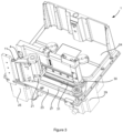
- rotation of the pulley wheel 30 in the clockwise direction drives the first arm 33 in to the left in Fig. 2 , causing the second arm 34 to move in a generally downward direction, and the printhead assembly 4 to move towards the printing surface 13.
- rotation of the pulley wheel 30 in the counter-clockwise direction in Figure 2 causes the printhead assembly 4 to move away from the printing surface 13.
- the belts 27, 31 may be considered to be a form of flexible linkage.
- the term flexible linkage is not intended to imply that the belts behave elastically. That is, the belts 27, 31 are relatively inelastic in a direction generally parallel to the direction of travel of the ribbon 2 and the substrate 12 past the printhead assembly 4 (i.e. the direction which extends between the pulley wheel 30 and the further pulley wheel 32).
- the belts 27, 31 will flex in a direction perpendicular to the direction of travel of the ribbon 2 and the substrate 12 past the printhead assembly 4, so as to allow the belts 27, 31 to move around the pulleys 26, 28, 30, 32.
- the printhead rotation belt 31 will flex in a direction perpendicular to the direction of travel of the ribbon 2 and the substrate 12 past the printhead assembly 4, so as to allow for the arc of movement of the first 33 arm about the pivot 22.
- a force applied to the first arm 33 by the printhead rotation belt 31 will be transmitted to the second arm 34 and the printhead 11.
- a force exerted by the printhead 11 on the printing surface 13 will be determined by the force exerted on the first arm 33 by the printhead rotation belt 31 - albeit with adjustment for the geometry of the first and second arms 33, 34.
- the force exerted on the first arm 33 by the printhead rotation belt 31 is in turn determined by the torque applied to the printhead rotation belt 31 by the motor 29 (via pulley wheel 30).
- a corresponding predetermined force can be established between the printhead 11 and the printing surface 13. That is, the motor 29 can be controlled to move the printhead 11 towards and away from the printing surface 13, and thus to determine the pressure which the printhead applies to the printing surface 13.
- the control of the applied pressure is important as it is a factor which affects the quality of printing.
- the motor 29 may also be controlled in a conventional way (e.g. an open-loop position-controlled way).
- the position of the printhead 11 with respect to the printing surface 13 is also affected by the motor 25. That is, given the relationship between the motor 25 and the printhead assembly 4 (i.e. the coupling of the motor 25, via the belt 27, to the printhead carriage 21), movement of the motor 25 also has an impact on the position of the printhead relative to the printing surface 13.
- the motor 25 may also be a stepper motor, and may be controlled in a conventional (i.e. open-loop) manner.
- the motors 25, 29 may be other forms of motor (e.g. DC servo motors) which can be controlled in a suitable manner to control the position of the printhead 11 and printhead assembly 4.
- ink carried on the ribbon 2 is transferred to the substrate 12 which is to be printed on.
- the print head 11 is brought into contact with the ribbon 2.
- the ribbon 2 is also brought into contact with the substrate 12.
- the printhead 11 is caused to move towards the ribbon 2 by movement of the print head assembly 4, under control of the controller 10.
- the print head 11 comprises printing elements arranged in a one-dimensional linear array, which, when heated, whilst in contact with the ribbon 2, cause ink to be transferred from the ribbon 2 and onto the substrate 12. Ink will be transferred from regions of the ribbon 2 which correspond to (i.e. are aligned with) printing elements which are heated.
- the array of printing elements can be used to effect printing of an image on to the substrate 12 by selectively heating printing elements which correspond to regions of the image which require ink to be transferred, and not heating printing elements which require no ink to be transferred.
- the print head 11 In continuous printing, during the printing phase the print head 11 is brought into contact with the ribbon 2, the other side of which is in contact with the substrate 12 onto which an image is to be printed.
- the print head 11 is held stationary during this process - the term "stationary" is used in the context of continuous printing to indicate that although the print head will be moved into and out of contact with the ribbon, it will not move relative to the ribbon path in the direction in which ribbon is advanced along that path. Both the substrate 12 and ribbon 2 are transported past the print head, generally but not necessarily at the same speed.
- the print head is extended into contact with the ribbon only when the print head 11 is adjacent regions of the substrate 12 to be printed.
- the ribbon 2 must be accelerated up to for example the speed of travel of the substrate 12.
- the ribbon speed is then generally maintained at a speed which is based upon the speed of the substrate (e.g. equal to, or proportional to the speed of the substrate 12) during the printing phase and, after the printing phase has been completed, the ribbon 2 must be decelerated and then driven in the reverse direction so that the used region of the ribbon is on the upstream side of the print head 11.
- the ribbon 2 is then accelerated back up to the normal printing speed and the ribbon 2 is positioned so that an unused portion of the ribbon 2 close to the previously used region of the ribbon is located between the print head 11 and the substrate 12 when the print head 11 is advanced to the printing location L P . It is therefore desirable that the supply spool motor 6 and the take-up spool motor 7 can be controlled to accurately locate the ribbon so as to avoid a printing operation being conducted when a previously used portion of the ribbon is interposed between the print head 11 and the substrate 12.
- a substrate is advanced past the printhead 11 in a stepwise manner such that during the printing phase of each cycle the substrate 12 and generally but not necessarily the ribbon 2 are stationary. Relative movement between the substrate 12, the ribbon 2 and the printhead 11 are achieved by displacing the printhead 11 relative to the substrate and ribbon. Between the printing phases of successive cycles, the substrate 12 is advanced so as to present the next region to be printed beneath the print head and the ribbon 2 is advanced so that an unused section of ribbon is located between the printhead 11 and the substrate 12. Once again accurate transport of the ribbon 2 is necessary to ensure that unused ribbon is always located between the substrate 12 and printhead 11 at a time that the printhead 11 is advanced to conduct a printing operation. It will be appreciated that where the intermittent mode is used, the printhead assembly 4 is caused to move along the linear track 23 so as to allow its displacement along the ribbon path.
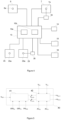
- both the supply spool motor 6 and the take-up spool motor 7 are energised in the same rotational direction. That is, the supply spool motor 6 is energised to turn the supply spool 3 to pay out an amount of tape while the take-up spool motor 7 is energised to turn the take-up spool 5 to take-up an amount of tape.
- the motors 6, 7 can therefore be said to operate in "push-pull" mode, with both motors being operated in a position (or speed) controlled manner.
- the ribbon 2 is controlled based upon the speed of the substrate 12 moving past the printhead 11.
- data indicative of the speed of movement of the substrate 12 may be obtained from the encoder 14.
- Such data may be referred to as a substrate speed.
- the supply and take up spool 3, 5 are caused to rotate by the motors 6, 7 so as to cause the ribbon 2 at the printing location L P to move at a linear speed which is substantially equal, or at least based upon, the substrate speed.
- the ribbon speed may be controlled so as to be a percentage (e.g. 96%) of the substrate speed.
- the speed of the ribbon 2 at the printhead 11 during printing in continuous mode may be referred to as a ribbon speed.
- each of the motors 6, 7 are controlled by the controller so as to move at an angular speed which causes ribbon to be advance at a predetermined linear speed past the printhead 11.
- the control of the motors to move at a predetermined angular speed results in the each of the motors being controlled to advance at a predetermined step rate.
- the motors are controlled by specifying times at which steps should be applied.
- the times at which these steps are applied may be determined based upon acceleration tables which are stored in a memory associated with the controller 10.
- the acceleration tables may contain data indicative of a set of motor speeds, and/or rates (which correspond to angular speeds) at which steps should be applied to the motors.
- the acceleration tables contain data indicative of a delay between motor steps for each of a set of motor speeds.
- the acceleration tables define transitions between step rates (which correspond to speeds) which can be achieved while operating within the operational limits of the motors. That is, a stepper motor may stall if accelerations or decelerations are attempted to be applied which require torques to be applied which are greater than the motor capabilities (whilst taking into account the inertia of spools of ribbon driven by the motors). As such, the acceleration tables contain data which is indicative of the maximum safe acceleration rates which can be applied to a motor.
- the acceleration tables may be based upon data indicative of the maximum angular acceleration rate for each motor, and may, for example, be re-calculated for each printing cycle so as to take into account current spool diameters values. That is, at the time of use (i.e. during a printing cycle) each acceleration table may already have been re-calculated based upon current spool diameter values so as to contain step rate data for a particular motor in a particular winding condition operating at various linear ribbon speeds. Thus, no adjustment for spool diameter is needed at the time at which the acceleration tables are accessed. Of course, it will be appreciated that the adjustment for spool diameter could be made at run-time if preferred. Alternatively, the acceleration tables could be updated at a different rate, for example, after each time a predetermined length (e.g. 750 mm) of ribbon has been transferred between the spools.
- a predetermined length e.g. 750 mm
- the acceleration tables for each motor in a printer may be generated so as to generally correspond to one another.
- the acceleration tables for the two motors may be generated such that the maximum linear acceleration rates are generally consistent for the two motors.
- a global maximum linear acceleration value (e.g. 25 m/s 2 ) may be used to generate the acceleration tables for both motors at all spool diameters.
- a maximum linear acceleration value may be selected based upon a rate at which a motor driving a spool having a maximum allowable spool diameter can be safely accelerated and decelerated without causing the motor to stall.
- acceleration tables generated for both of the motors 6, 7 provide a common maximum linear acceleration, for any particular actual motor speed, and a desired new ribbon speed, the two motors may have to respond to the speed demand differently. That is, given the different step sizes (in terms of linear distance of tape moved per step), the acceleration table for each motor will contain different speed entries, with different allowable speed steps based upon the current spool diameters.
- the updated desired ribbon speed is then converted into motor step rates by looking up the most suitable (and achievable) step rate in the relevant acceleration table.
- a modified step rate is determined with reference to the acceleration tables, the modified step rate being a step rate which is as close to the desired step rate as can be achieved without exceeding an allowable acceleration. Steps are then applied to each of the motors at the modified (i.e. achievable) step rates. Where the closest achievable step rate to a desired step rate (e.g. as determined based upon the desired ribbon speed) is below the desired step rate, the step rate will be updated again at the next refresh cycle (i.e. after a next step has been applied), so as to allow the motor to be accelerated towards the desired speed over two (or more) steps.
- the acceleration table for each motor may include entries as shown in Table 1.
- Each entry in each of the tables is representative of a linear ribbon speed.
- the speeds are calculated as the linear speed that is reached at the circumference of the spool by moving the motor a single step, with the spool being accelerated at the maximum permissible acceleration during that step, starting either a stationary position (entry 1), or the previous speed entry (entries 2 and onwards).
- the tables can be consulted to determine an allowable next speed. It is not permitted to make more than a single speed jump in the table in a single step, so if a desired speed change exceeds the permitted change, the desired speed change is applied over two (or more) steps.
- the next step applied to the motors will cause each motor to accelerate, but will cause the supply spool motor to accelerate to 210.19 mm/s (entry 9), whereas the take up spool motor will be caused to accelerate to the desired speed of 220 mm/s.
- the subsequent step for the supply spool will allow the speed to increase from 210.19 mm/s (entry 9) to up to 221.56 mm/s (entry 10). As such, a speed of 220 mm/s will be selected and, after two steps, the supply spool motor will also be at the desired speed.
- the ribbon movement may be controlled based upon substrate movement in different ways.
- an image printed by the printer on the substrate having a first length may result in a negative image having a different length being formed on the ribbon.
- a printed image of 70 mm in length may result in a negative image of 69 mm being formed.
- the ribbon may be controlled during and between printing operations such that the portion of unused ribbon between adjacent negative images is minimised.
- the different step rates result in there being different effective sampling rates of the desired speed for each of the motors, and therefore different speed errors, resulting in different accumulated distance errors.
- a desired speed fluctuates rapidly (e.g. due to a noisy substrate encoder signal)
- this can have a significant cumulative effect where one motor can track the noise, whereas another cannot.
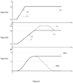
- a first distance error threshold T1 of ⁇ 0.1 mm may be provided. If the cumulative error exceeds this threshold T1, a first speed scaling factor S1 of 0.5 % (positive or negative as required) may be applied.
- a similar process may be performed independently for each of the spools 3, 5.
- a modified speed profile Vsu' is also shown as a dashed line.
- the modified speed profile Vsu' rather than the acceleration (at the maximum rate A2) stopping when the speed V2 is reached, the spool is accelerated (at the maximum rate A2) for longer, to a speed V2+ which is 2% greater than the speed V2.
- the modified cumulative error ERR2 is shown in Figure 6c . Rather than remaining fixed after the acceleration has been completed (as does ERR1), the modified cumulative error ERR2 is reduced due to the effect of increasing the spool speed to V2+, until the error falls below the threshold T1. The increased spool speed V2+ is thus maintained until the error has been reduced, at which time the spool speed Vsu is reduced to the speed of the substrate V2.
- data indicative of the increase (or decrease) of ribbon path length may be provided to the feed correction block 41.
- Such data may be referred to a printhead position data PH POS .
- one or more of the threshold values and/or speed scaling factors may be modified in order to respond quickly to an expected disturbance.
- the speed scaling factor S2 associated with the second threshold level T2 may be increased based upon the ribbon path length error to be injected.
- the scaling factor adjustment may, for example, be calculated based upon the magnitude of the path length adjustment to be made, the current ribbon target speed, and the anticipated time it will take the printhead to complete the movement.
- the T2 off level TO2 may be adjusted prevent any overshoot. For example, if the speed scaling factor is increased, the likelihood of overshoot is increased. Therefore, the threshold at which the speed scaling factor is reduced may also be increased, so as to lessen any overshoot (i.e. so that the speed scaling reverts to the first speed scaling factor S1 more quickly).
- the second threshold T2 is reduced to the extent that it is the same as the first threshold T1.
- the second speed scaling factor S2 is applied as soon as the first threshold T1 (and second threshold T2) is reached. This may be preferred where any path length adjustment is small (e.g. where there is a small gap between the ready to print position and the printing position). For example, if no T2 adjustment was made, an error which is just below the second threshold T2 level (e.g. 0.3 mm) may only be corrected by a small (e.g. 0.5 %) speed scaling factor, and may thus take some considerable time to be corrected. However, where the second speed scaling factor S2 is adjusted based upon the required correction (e.g.
- the data indicative of the printhead position PH POS may be used only to the adjust control of the supply spool motor 3. Such control may be considered to reduce the likelihood of rapid tension changes being caused between the take up spool 5 and the printhead 11, which could have a detrimental effect on ribbon peel angle, and therefore print quality.
- a printhead movement may span several motor steps. Indeed, in some embodiments, a printhead movement may take around 10 ms, which may, for example, span 500 tape drive motor steps.
- the printhead position data PH POS may be modified across several steps, so as to provide accurate and up to date information regarding the actual ribbon path length at every point in time (rather than assuming that the printhead movement is instantaneous). In this way, any speed adjustment made by the ribbon feed correction block 41 may be distributed over several motor steps.
- the printhead movement is instantaneous, on the basis that the maximum acceleration for the motors 6, 7 may limit the rate at which the tape drive can respond, and thus the response to the printhead position movement will effectively be distributed over several steps by the limited acceleration.
- the path length error is injected to the error accumulator as soon as the printhead movement begins.
- the printhead position data PH POS may be generated in any convenient way.
- the printhead position data PH POS may be generated with reference to the motor 29 which controls the movement of the printhead 11.
- the printhead position data PH POS may be generated by monitoring steps applied by the motor 29.
- the printhead movement data may be generated with reference to the encoder 36 associated with the motor 29. For example, it may be assumed that any movement of the motor shaft 29a will correspond to a movement of the printhead 11.
- the position of the printhead 11 can be determined by reference to the motor 29, and the motor 25. That is, for a given angular position of the motor shafts 25a, 29a, there is a predictable angle of the arms 33, 34, and thus a predictable position of the printhead 11 with respect to the body of the printer 1.
- the offset may be empirically determined to provide robust detection of the printing location L P .
- the offset may vary depending upon the printing force and other configuration changes (e.g. a change in print roller).
- Figure 7a shows schematically the printhead 11 in a ready to print location L RTP , spaced apart from the printing surface 13 (in this case a platen roller). It can be seen that the ribbon 2 is in contact with the printhead 11, and is guided at the downstream edge of the printhead by the roller 20. However, the printhead 11 is spaced apart from the printing location L P .
- Processing passes to steps S104, where the apparent printing location L P-APPARENT is compared to reference data so as to determine if the apparent printing location L P-APPARENT is within an a acceptable range (e.g. a platen separations of 0 mm to 5 mm).
- a acceptable range e.g. a platen separations of 0 mm to 5 mm.
- data indicating an acceptable range may be provided in terms of encoder values corresponding to acceptable physical positions. If the value is not in an acceptable range, a fault is raised to the user at step S105.
- any portion of ribbon which passes between the light source 16 and the camera 15 at the imaging location L I has, in normal operation, already passed the printing location L P .
- portions of ribbon may be advanced from the supply spool 3 to the take up spool 5 and then re-wound in the opposite direction, for example, so as to ensure a particular portion of unused ribbon is presented at the printing location for a printing operation without wasting ribbon.
- ribbon is generally advanced from the supply spool 3 to the take up spool 5 in a first direction, the printhead 11 (and the printing location L P ) being upstream of the camera 15 (and the imaging location L I ).
- the separation between the printing location L P and the imaging location L I may be referred to as an imaging distance D I .
- the camera 15 comprises a sensor 60 having a plurality of pixels (not shown).
- the sensor 60 comprises 256 pixels arranged in a one-dimensional linear array.
- the pixel array extends in a direction substantially parallel to the linear array of LEDs 50 in the light source 16. Radiation incident upon the camera is focused and directed towards the sensor 60 by a lens assembly 61.
- the lens assembly 61 provides a wide angle field of view, allowing radiation to be captured from the full width of the light source 16.
- the senor 60 comprises a 256 element linear photodiode sensor array having integral charge amplifier circuitry such as, for example, the TSL1402R as manufactured by Texas Advanced Optoelectronic Solutions Inc, of Plano, Texas.
- the sensor may produce two analog outputs (each relating to 128 sensor elements), which are passed to respective ADC chips (e.g. AD 7278, manufactured by Anaog Devices Inc, of Norwood, Massachusetts).
- the ADC chips may each provide a 128-bit serial data output via an SPI interface, each having 8-bits of intensity data per pixel of the sensor.
- Processing then passes to step S209 where the image capture block 62 is operated to capture a full width intensity distribution IM LED_PAIR from the image sensor 60.
- the captured intensity distribution IM LED_PAIR comprises a respective data item indicative of the radiation intensity incident upon each of the 256 pixels as a result of the half-intensity illumination of the selected LED pair.
- Process then passes to step S217 where a full width intensity distribution IM BG_NO_RIBBON is captured from the image sensor 60.
- the captured image comprises a data item indicative of the radiation intensity incident upon each of the 256 pixels.
- step S2128 When it is detected that a cassette holding ribbon is inserted into the printer, processing passes to step S218, where the LEDs 50 are driven at the corrected nominal drive intensity LED CORRECT_NOMINAL . All of the LEDs are driven simultaneously.
- Processing then passes to step S219 where a further full width intensity distribution IM RIBBON is captured from the image sensor 60 and stored.
- the captured data comprises a data item indicative of the radiation intensity incident upon each of the 256 pixels.
- Processing then passes to step S220 where it is determined, from the ribbon intensity distribution IM RIBBON , if ribbon is present at each region within the image.
- the presence or absence of ribbon may, for example be detected by applying a threshold level to the ribbon intensity distribution IM RIBBON .
- an edge detection algorithm may be applied to the ribbon intensity distribution IM RIBBON to identify any ribbon edges.
- the intensity recorded with ribbon present is processed at step S221 to generate background intensity distribution IM BG to replace that obtained during step S217.
- background intensity distribution IM BG_NO_RIBBON provides useful information regarding the relative difference between the brightness of different image regions, no account is taken of the type of ribbon actually installed in the printer. For example, depending on the type and/or colour of ribbon installed, there may be significant variations in transmittance.
- the relevant pixels of the intensity distribution IM BG are populated with data extracted from the intensity distribution IM RIBBON .
- the value stored in each of the pixels of the intensity distribution IM BG_NO_RIBBON corresponding to a location where ribbon is present is replaced by the value stored in the corresponding pixels of the intensity distribution IM RIBBON .
- the value stored in each of the pixels of the intensity distribution IM BG_NO_RIBBON corresponding to a location where ribbon is present is scaled by a scaling factor determined to cause the scaled value to be equal to the value stored in the corresponding pixels of the intensity distribution IM RIBBON .
- improved background data for the regions where ribbon is not present is generated at a further processing step S222 based upon the ribbon intensity distribution IM RIBBON obtained at step S219, and the background intensity distribution obtained with no ribbon present IM BG_NO_RIBBON at step S217 to provide appropriate background data for the locations where ribbon is not present.
- the corresponding pixels of the ribbon intensity distribution IM RIBBON are scaled by an amount equal to the average adjustment applied at step S221 to the pixels where ribbon is present.
- the pixels of the improved background intensity distribution IM BG corresponding to locations where ribbon is not present are populated with values which take into account both non-ideal system behaviour, and expected ribbon transmittance characteristics.
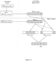
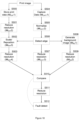
- Figures 13 and 14 provide an illustration of background data generation. The various data sets generated and relationships therebetween is illustrated in Figure 13 .
- the horizontal axis shows pixel location (with 32 pixels shown in this example), while the vertical axis shows the pixel intensity.
- a first line shows the background intensity distribution obtained with no ribbon present IM BG_NO_RIBBON captured at step S217. It can be seen that this line includes an apparently random noise profile, with no clear features or trend visible across the image width.
- a third line shows the improved background intensity distribution IM BG .
- this is simply the same as the ribbon intensity distribution IM RIBBON .
- the ribbon intensity distribution IM RIBBON has been scaled such the intensity distribution IM BG is at approximately the same level across the width of the image, with the noise profile seen in IM BG_NO_RIBBON still present.
- the parts of the intensity distribution IM BG_NO_RIBBON where ribbon is not present may be scaled (while retaining the relative differences between pixels) such that the average value of those pixels is equal to the average intensity value in the regions of the ribbon intensity distribution IM RIBBON where ribbon is present.
- background intensity distribution IM BG is generated for the full width of the imaging location L I based upon the background intensity distribution obtained with no ribbon present IM BG_NO_RIBBON and the intensity distribution obtained with ribbon present IM RIBBON .
- an additional processing step may be performed between stages N2 and N3 in which all LEDs are driven at the corrected nominal intensity LED CORRECT_NOMINAL .
- image data may be obtained from the camera 15 and a further adjustment may be made to the LED drive intensities to avoid over or under exposure of particular sensor regions (and thus parts of ribbon).
- any image data obtained which indicates that intensity saturation is occurring e.g. a completely flat, and maximum intensity level
- the processing described above is primarily concerned with image intensity adjustments to compensate for non-uniformities in the sensor and emitter configuration, and differences between transmittance of different ribbons. Moreover, the processing described makes use of one-dimensional data arrays captured by a one-dimensional sensor.
- the camera 15 is intended to provide two-dimensional imaging, so as to allow captured image data to be compared with intended printed image data, thereby allowing printing quality to be assessed.
- further processing may be performed in order to accurately calibrate the length, width, and/or position of captured image data, so as to allow for proper image registration, and thus region by region image comparison.
- a one-dimensional line scan i.e. a one-dimensional distribution of radiation intensity
- a two-dimensional image is built by assembling a plurality of one-dimensional image array, or image slices, each image slice being associated with a particular region of ribbon.
- the capture of a two-dimensional image by a one-dimensional sensor requires an effective pixel dimension to be determined in the imaging direction. That is, the one-dimensional array has a length in a direction perpendicular to the ribbon travel direction, with each pixel representing a region which is a proportion of that length.
- each pixel is square, unless the ribbon transport past the imaging location is accurately controlled, and that control calibrated, it may be that the effective length of each pixel in the direction of ribbon transport (i.e. not the imaging direction) is different from that in the direction in which the sensor extends.
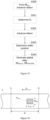
- FIG. 15 A process by which the camera is calibrated for this purpose is now described with reference to Figure 15 .
- Processing starts at step S300, where the printer is controller to begin printing a calibration pattern P CAL on a substrate.
- Figure 16 shows schematically a portion of ribbon 2 upon which the calibration pattern P CAL has been printed.
- the calibration pattern P CAL has known dimensions, and may, for example, be a solid rectangle having a length L CAL in the direction D, and a width W CAL in a direction perpendicular to the direction of ribbon movement.
- the dimension of the calibration pattern P CAL may be pre-selected based upon the ribbon width, before step S300. It will be appreciated that for narrower ribbon, a calibration pattern P CAL with a smaller dimension may be used.
- the calibration pattern P CAL may extend for a predetermined percentage of the ribbon width.
- the ribbon is advanced past the printing location L P so as to move the ribbon 2 past the printhead 11, which remains stationary.
- the substrate 12 is also advanced past the printhead 11. During this movement, the number of pulses moved by the encoder associated with the take up spool motor 7 is monitored continually.
- the distance moved by the ribbon between the printing location L P and the imaging location L I is determined. As noted above, this distance may be referred to as an imaging distance D I .
- the imaging distance D I may not correspond to a straight-line distance within the printer 1. Rather, the distance D I is indicative of a linear distance travelled by the ribbon between the printing location L P and the imaging location L I .
- this distance changes during operation as the printhead is scanned along the length of an image. Further, even in continuous printing the distance is subject to changes in configuration (e.g. changes in the position of the printhead in the ribbon movement direction).
- the distance D I determined as described above may be used as a reference distance. In subsequent processing, the offset between the current printhead position and the printhead position when the distance D I was determined can be used to allow the distance between current printhead position and the imaging location L I to be known at that time, for example to enable accurate ribbon tracking and image registration.
- Step S302 ribbon is advanced by a further distance (which may, for example, correspond to at least the known length L CAL of the calibration pattern P CAL ).
- the camera continues to obtain images of the ribbon at the imaging location L I , the images being combined into a captured calibration image IM CAL_CAPTURE .
- processing passes to step S304 where an image scaling factor IM SCALE is generated.
- the image scaling factor IM SCALE is generated based upon the ratio between the known width W CAL of the calibration pattern P CAL and the apparent width W CAL _ APPARENT determined at step S303.
- the second scaling factor allows the captured images to be compared to equivalently sized expected images along the ribbon movement direction D. It has been found that the friction between the printhead and the ribbon during printing may drag the ribbon along a direction opposite to the ribbon movement direction D, such that the length of the ribbon used for printing may be slightly shorter than the length of the printed image. For example, if the length of the printed image (and thus the nominal expected negative image on the ribbon) is 70mm, the length of the actual negative image on the ribbon may be around 69mm. As such, the size of the expected negative image on the ribbon may be adjusted by the second scaling factor to compensate for this effect. As noted above, this effect may be taken into account by the ribbon transport system to avoid unnecessary wastage of ribbon.
- the extent of the stretch may vary in dependence upon the print speed. For example, the extent of the stretch may increase with increasing print speed. This may result from the printhead tending to apply a larger dragging force to the ribbon at higher print speeds than at lower print speeds.
- the second scaling factor allows the stretching deformation of the ribbon to be compensated for, thereby allowing the captured images to be more accurately registered to the expected images.
- Adjustments to the second scaling factor to account for speed may be determined empirically and appropriate scaling factor adjustment values stored in a lookup table in a memory associated with the controller 10. For example, scaling factor adjustment values may be established during laboratory testing, and an appropriate one of the stored values accessed during operation based upon the print speed. Of course, it will be understood that alternative techniques may be used. For example, a small number of adjustment values may be stored and intermediate values determined by interpolation. Alternatively, or additionally, the scaling factor value may be determined and adjusted based upon the apparent length L CAL_APPARENT of a calibration pattern as described above, with a calibration pattern being printed at an appropriate speed.
- the calibration pattern may be modified based upon knowledge of defective printing elements.
- adjustments may be made to the expected capture image based upon knowledge of any defective printing elements.
- the second total expected light level will typically be higher than the first total expected light level.
- a threshold level may be determined based on the first and second expected light level values. The threshold level may then be used to identify the position of the leading edge of the calibration pattern P CAL in the direction of ribbon movement.
- this technique allows an aggregate or total received light level to be used to identify approximately where the calibration pattern P CAL is located on the ribbon as the ribbon is transported past the sensor 60.
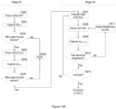
- the obtained intensity distribution ID1 is then processed at step S403 to generate an average intensity value indicative of the average intensity upon the active areas of the sensor 60.
- the first and last eight pixels of the sensor may be disregarded for this process, on the basis that they may be partially blocked by mechanical arrangements, and therefore may receive less radiation than other regions of the sensor.
- Processing then passes to step S404, where it is determined if the average intensity value satisfies a predetermined criterion.
- the average intensity value is compared to a threshold, such as, for example one third of the maximum intensity value. If the average value exceeds this threshold, processing passes to step S405.
- step S408 if there are four or more obscured pixels, processing passes to step S408, where, a maximum number of contiguous obscured pixels is determined. Processing then passes to step S409.
- a highest ratio between the obscured pixels and good pixels is determined.
- This ratio may, for example, be determined by considering pixels one by one from the cassette end of the image (i.e. the end furthest from the baseplate 16). Only the portion of the image relating to the expected ribbon width is considered (e.g. where a 30 mm ribbon is used, with an imaging width of around 63 mm, around half of the image is considered only). As each pixel is considered in turn, a ratio is kept of good pixels (i.e. over the two-thirds nominal brightness) to obscured pixels. In order to prevent a small number of pixels at the image edge from distorting the output, the ratio, the maximum ratio is only considered once 24 pixels (or around 6 mm of sensor width) have been considered. Thereafter, the process continues to consider each of the remaining pixels (until the currently configured ribbon width is reached), and the ratio is calculated after each pixel has been considered. Once the currently configured ribbon width is reached, the maximum ratio is recorded.
- step S412 If neither of these thresholds are met, processing passes to step S412 where the sensor is indicated as being dirty. Processing proceeds from step S412 to step S413 where it is determined if there have been three consecutive 'dirty' results. If no, processing passes to step S414, where a short delay (e.g. 1/3 second) is inserted, before processing returns to step S402, and the process described above is repeated.
- a short delay e.g. 1/3 second
- the expected image start position IM POSITION (i.e. a position of the image in a direction perpendicular to the direction of ribbon movement past the printhead 11 and the camera 15) may vary over time. As such, whereas the expected image start position IM POSITION may be determined during a calibration routine as described above, this position may be adjusted during ongoing printing operations. For example, the expected image start position IM POSITION may be adjusted before printing each image of a print job. This approach allows the image processing techniques described herein to accommodate ribbon drift across the printhead 11.
- each of the 63 pixels in each row of the image is generated based upon 8 pixels in each direction (64 pixels in total), with each one of the new 63 pixels overlapping with the adjacent new pixel by 50 %. Further, each pixel is based upon a weighted average of the intensity of the 64 pixels around the new pixel location. For example, in an embodiment the central 2x2 pixels are each weighted at 100 %, while the ring of pixels immediately surrounding this 2x2 block are weighted at 60% (12 pixels). A next ring of pixels around the central 4x4 block are weighted at 20 % (20 pixels).
- This additional reduction in resolution provides a degree on insensitivity to alignment errors. It has been realised that while such processing may cause a loss in detail (i.e. as image features become blurred), it may improve the ability to compare equivalent parts of the expected image data and the captured image data, especially where the ribbon position with respect to the camera in a direction perpendicular to ribbon movement has changed slightly during operation. Similarly, the expected and captured image positions may vary with respect to each other in the direction of ribbon movement due to inaccurate ribbon control, for example due to eccentricities in the ribbon spools. Thus, by blurring the images across several pixels, it is possible to examine the correspondence, on average, of each region of the images. The extent to which the resolution is reduced at this stage is a compromise between, on the one hand, a desire to reduce sensitivity to tracking errors, and on the other, a desire to maintain sufficient image detail.
- Processing then passes to step S506 where edges of the ribbon in the normalised captured image IM CAPT 2 are identified.
- This edge detection may, for example, be performed by analysing the region of each image where the ribbon edges are expected to be, and identifying the pixel position close to that location at which an abrupt change in image intensity is observed. The edge detection process may be performed for each image line. The output of this process is passed to step S502, where the actual ribbon location is used to construct and position the expected image.
- Step S507 the resolution of the normalised captured image IM CAPT 2 is adjusted to form a reduced resolution captured image IM CAPT 3 that has a convenient resolution for subsequent processing, and the same as the resolution of the reduced resolution image IM EXP 4 generated at step S503.
- the reduced resolution captured image IM CAPT 3 may have a resolution resulting in there being 63 pixels defining a width of the image (rather than 256 pixels).
- a further process is performed at step S508 to generate a background only image.
- This image IM BG 1 is based upon the one-dimensional background intensity distribution IM BG , but extended to form an image having the same length as each of IM CAPT 3 and IM EXP 4.
- data outside of the detected ribbon edges is set to zero.
- data indicative of the printhead position (which causes deflection of the ribbon 2) can be provided as an input to the ribbon tracking controller.
- the ribbon tracking controller can use the printhead position data PH POS to modify the apparent offset between the printing location and the imaging location. That is, the calibration process described above with reference to Figure 15 provides a printhead reference position (with respect to the imaging location L I ), with any deviation from that position being determined based upon the printhead position data PH POS .
- print quality may be defined based upon a number of pixels printed which correspond to the pixels intended to be printed.
- print quality may be defined by comparing a total number of pixels printed in an image with a number of pixels intended to be printed.
- a print quality metric may be based upon a relative darkness of the printed image (or relative "lightness" of ribbon after printing).
Landscapes
- Physics & Mathematics (AREA)
- Electromagnetism (AREA)
- Engineering & Computer Science (AREA)
- Mechanical Engineering (AREA)
- Impression-Transfer Materials And Handling Thereof (AREA)
- Electronic Switches (AREA)
Applications Claiming Priority (4)
| Application Number | Priority Date | Filing Date | Title |
|---|---|---|---|
| GBGB1710351.6A GB201710351D0 (en) | 2017-06-28 | 2017-06-28 | Tape drive and method |
| GBGB1710350.8A GB201710350D0 (en) | 2017-06-28 | 2017-06-28 | Transfer printer and method |
| PCT/GB2018/051796 WO2019002857A1 (fr) | 2017-06-28 | 2018-06-27 | Imprimante à transfert et procédé associé |
| EP18739589.2A EP3645295B1 (fr) | 2017-06-28 | 2018-06-27 | Imprimante à transfert et procédé associé |
Related Parent Applications (1)
| Application Number | Title | Priority Date | Filing Date |
|---|---|---|---|
| EP18739589.2A Division EP3645295B1 (fr) | 2017-06-28 | 2018-06-27 | Imprimante à transfert et procédé associé |
Publications (2)
| Publication Number | Publication Date |
|---|---|
| EP4393719A2 true EP4393719A2 (fr) | 2024-07-03 |
| EP4393719A3 EP4393719A3 (fr) | 2024-09-25 |
Family
ID=62873491
Family Applications (4)
| Application Number | Title | Priority Date | Filing Date |
|---|---|---|---|
| EP18739589.2A Active EP3645295B1 (fr) | 2017-06-28 | 2018-06-27 | Imprimante à transfert et procédé associé |
| EP24172482.2A Pending EP4393719A3 (fr) | 2017-06-28 | 2018-06-27 | Imprimante à transfert et procédé associé |
| EP20207920.8A Active EP3800058B1 (fr) | 2017-06-28 | 2018-06-27 | Entraînement de bande et procédé associé |
| EP18739588.4A Active EP3645294B1 (fr) | 2017-06-28 | 2018-06-27 | Imprimante avec entraînement de bande et procédé associé |
Family Applications Before (1)
| Application Number | Title | Priority Date | Filing Date |
|---|---|---|---|
| EP18739589.2A Active EP3645295B1 (fr) | 2017-06-28 | 2018-06-27 | Imprimante à transfert et procédé associé |
Family Applications After (2)
| Application Number | Title | Priority Date | Filing Date |
|---|---|---|---|
| EP20207920.8A Active EP3800058B1 (fr) | 2017-06-28 | 2018-06-27 | Entraînement de bande et procédé associé |
| EP18739588.4A Active EP3645294B1 (fr) | 2017-06-28 | 2018-06-27 | Imprimante avec entraînement de bande et procédé associé |
Country Status (4)
| Country | Link |
|---|---|
| US (3) | US11801689B2 (fr) |
| EP (4) | EP3645295B1 (fr) |
| CN (4) | CN110997339B (fr) |
| WO (2) | WO2019002856A1 (fr) |
Families Citing this family (9)
| Publication number | Priority date | Publication date | Assignee | Title |
|---|---|---|---|---|
| WO2019002856A1 (fr) * | 2017-06-28 | 2019-01-03 | Videojet Technologies Inc. | Entraînement de bande et procédé associé |
| CN114434991B (zh) * | 2020-11-06 | 2023-06-16 | 湖南鼎一致远科技发展有限公司 | 热转印打印机的控制方法和热转印打印机 |
| CN113879011B (zh) * | 2021-11-08 | 2024-05-24 | 北京中馨智信科技有限公司 | 打印控制装置及打印控制方法 |
| CN115534544B (zh) * | 2022-10-10 | 2024-12-13 | 百富计算机技术(深圳)有限公司 | 热敏打印机的打印方法、打印机、打印系统及存储介质 |
| GB202216635D0 (en) * | 2022-11-08 | 2022-12-21 | Dover Europe Sarl | Improved printer and method of controlling ribbon drive in a printer |
| US12208635B2 (en) * | 2023-02-27 | 2025-01-28 | Printronix, Llc | Adaptive ribbon speed control systems and methods |
| CN116552131B (zh) * | 2023-06-21 | 2025-11-28 | 软控股份有限公司 | 用于打标色带的卷曲计算方法及打标装置 |
| CN116968458B (zh) * | 2023-08-01 | 2024-04-02 | 上海迪凯标识科技有限公司 | 一种打印机色带的控制方法、装置、电子设备及存储介质 |
| CN116985536B (zh) * | 2023-08-15 | 2025-07-22 | 上海迪凯标识科技有限公司 | 打印机 |
Citations (3)
| Publication number | Priority date | Publication date | Assignee | Title |
|---|---|---|---|---|
| US7150572B2 (en) | 2000-09-11 | 2006-12-19 | Zippher Limited | Tape drive and printing apparatus |
| WO2013025746A1 (fr) | 2011-08-15 | 2013-02-21 | Videojet Technologies Inc. | Imprimante à transfert thermique |
| WO2016067052A1 (fr) | 2014-10-31 | 2016-05-06 | Videojet Technologies Inc. | Imprimante et procédé |
Family Cites Families (49)
| Publication number | Priority date | Publication date | Assignee | Title |
|---|---|---|---|---|
| JPS6019542A (ja) | 1983-07-14 | 1985-01-31 | Nec Corp | ドツトマトリクスプリンタの印字検査方法 |
| JPS6064878A (ja) | 1983-09-20 | 1985-04-13 | Matsushita Electric Ind Co Ltd | 感熱転写型カラ−プリンタ− |
| JPS60131286A (ja) * | 1983-12-20 | 1985-07-12 | Nec Corp | 熱転写プリンタの印字アラ−ム検出回路 |
| JPS60131286U (ja) * | 1984-02-07 | 1985-09-03 | トヨタ自動車株式会社 | 溶接ワイヤ接続外周部のバリ取り工具 |
| JPS61123567A (ja) | 1984-11-21 | 1986-06-11 | Mitsubishi Electric Corp | 転写装置 |
| CN1037870A (zh) | 1988-05-19 | 1989-12-13 | 张福林 | 舰船防晕床 |
| JPH02141277A (ja) | 1988-11-21 | 1990-05-30 | Pfu Ltd | プリンタ印字制御方式 |
| JPH02303882A (ja) | 1989-05-18 | 1990-12-17 | Citizen Watch Co Ltd | サーマルプリンタのリボン弛み除去方法 |
| DE4113648A1 (de) | 1991-04-26 | 1992-10-29 | Philips Patentverwaltung | Verfahren zur einstellung eines druckspaltes bei einem drucker, z. b. bei einem matrixdrucker, und anordnung zur durchfuehrung des verfahrens |
| CA2078903C (fr) | 1991-12-13 | 1998-08-18 | Gordon Brent Barrus | Mecanisme d'entrainement de ruban d'imprimante |
| JPH07149022A (ja) | 1993-11-30 | 1995-06-13 | Mitsubishi Electric Corp | カラー熱転写プリント装置 |
| JP3089936B2 (ja) | 1994-02-08 | 2000-09-18 | 日本ビクター株式会社 | インクリボンの巻取制御装置 |
| JPH07251517A (ja) | 1994-03-16 | 1995-10-03 | Tec Corp | サーマル転写式プリンタ |
| US5647679A (en) * | 1996-04-01 | 1997-07-15 | Itw Limited | Printer for printing on a continuous print medium |
| JP2000062232A (ja) * | 1998-08-19 | 2000-02-29 | Nikon Corp | 画像記録装置 |
| JP3539484B2 (ja) | 2000-03-07 | 2004-07-07 | 日本電気株式会社 | データ処理方法および装置、情報記憶媒体 |
| GB0123303D0 (en) | 2001-09-28 | 2001-11-21 | Zipher Ltd | Tape drive |
| GB0319091D0 (en) | 2003-08-14 | 2003-09-17 | Markem Tech Ltd | Printing apparatus |
| US7184068B2 (en) | 2003-09-18 | 2007-02-27 | Intermec Ip Corp. | Subsurface imaged labels and tags using thermal transfer ribbon carrier as overlaminate and method of manufacture |
| JP2005119065A (ja) | 2003-10-15 | 2005-05-12 | Konica Minolta Photo Imaging Inc | 熱転写プリンタおよび証明用写真撮影装置 |
| JP4525212B2 (ja) | 2004-07-07 | 2010-08-18 | 船井電機株式会社 | 熱転写プリンタ |
| GB2424853B (en) * | 2005-04-06 | 2008-07-16 | Markem Tech Ltd | Method of printing |
| US7382453B2 (en) * | 2006-02-14 | 2008-06-03 | Alberta Research Council Incorporated | Apparatus and method for characterizing an interfacial property of a dispersion |
| GB2448303B (en) * | 2007-03-07 | 2009-03-11 | Zipher Ltd | Tape drive |
| GB2448304B (en) * | 2007-03-07 | 2009-03-11 | Zipher Ltd | Tape drive |
| GB2448305B (en) | 2007-03-07 | 2009-03-11 | Zipher Ltd | Tape drive |
| JP4929032B2 (ja) | 2007-04-26 | 2012-05-09 | 日本電産サンキョー株式会社 | 印刷装置 |
| GB2449676B (en) | 2007-05-31 | 2009-08-26 | Zipher Ltd | Tape Drive |
| JP2010083091A (ja) * | 2008-10-02 | 2010-04-15 | Seiko Epson Corp | テープ印刷装置 |
| US7940377B1 (en) * | 2008-12-05 | 2011-05-10 | Sandia Corporation | Passive background correction method for spatially resolved detection |
| AU2008258180B2 (en) * | 2008-12-17 | 2011-02-17 | Canon Kabushiki Kaisha | Method for determining printer characteristics |
| EP2547525A1 (fr) | 2010-03-18 | 2013-01-23 | J P Imaging Limited | Perfectionnements apportés à l'impression ou s'y rapportant |
| JP4853749B1 (ja) | 2010-12-15 | 2012-01-11 | 真寿男 曽我部 | インクリボン走行部の構造 |
| CN202088782U (zh) * | 2011-05-24 | 2011-12-28 | 太仓丽盛制版有限公司 | 一种两面印刷仿真装饰膜 |
| US9168774B2 (en) * | 2012-01-06 | 2015-10-27 | Zih Corp. | Tri-state detector for detecting types of light |
| DE102012013487B4 (de) | 2012-07-09 | 2024-06-13 | Illinois Tool Works, Inc. | Vorrichtung zum thermischen Drucken oder Prägen |
| US9004629B2 (en) * | 2012-12-17 | 2015-04-14 | Xerox Corporation | Image quality by printing frequency adjustment using belt surface velocity measurement |
| GB2510832B (en) * | 2013-02-13 | 2020-02-26 | Dover Europe Sarl | Tape drive and method of operation of a tape drive |
| CN105408121B (zh) * | 2013-10-11 | 2017-10-13 | 录象射流技术公司 | 热转印打印机及贴标机 |
| GB201318575D0 (en) | 2013-10-21 | 2013-12-04 | Videojet Technologies Inc | Tape drive and transfer printer |
| GB2519525A (en) * | 2013-10-22 | 2015-04-29 | Videojet Technologies Inc | Machine and method of operation |
| CN204095305U (zh) * | 2014-06-19 | 2015-01-14 | 童建兴 | 一种同步打印的热转印打码机 |
| CN105291599A (zh) * | 2014-06-19 | 2016-02-03 | 童建兴 | 一种同步打印的热转印打码机及同步打印方法 |
| GB201419464D0 (en) | 2014-10-31 | 2014-12-17 | Videojet Technologies Inc | Tape drive and transfer printer |
| TWI570399B (zh) | 2014-12-04 | 2017-02-11 | 致茂電子股份有限公司 | 可校正光源之檢測系統及其光源校正方 法 |
| US9327498B1 (en) * | 2015-03-04 | 2016-05-03 | Xerox Corporation | System and method for applying electromagnetic ink to a non-electromagnetic ink image |
| JP6520271B2 (ja) | 2015-03-20 | 2019-05-29 | 日本電気株式会社 | 印刷物検査装置及び印刷物検査方法 |
| GB2542549B (en) | 2015-07-06 | 2020-12-09 | Dover Europe Sarl | A method of operating a tape drive |
| WO2019002856A1 (fr) * | 2017-06-28 | 2019-01-03 | Videojet Technologies Inc. | Entraînement de bande et procédé associé |
-
2018
- 2018-06-27 WO PCT/GB2018/051795 patent/WO2019002856A1/fr not_active Ceased
- 2018-06-27 CN CN201880055792.9A patent/CN110997339B/zh active Active
- 2018-06-27 CN CN202210277480.0A patent/CN114559749B/zh active Active
- 2018-06-27 US US16/624,613 patent/US11801689B2/en active Active
- 2018-06-27 EP EP18739589.2A patent/EP3645295B1/fr active Active
- 2018-06-27 EP EP24172482.2A patent/EP4393719A3/fr active Pending
- 2018-06-27 EP EP20207920.8A patent/EP3800058B1/fr active Active
- 2018-06-27 CN CN201880044145.8A patent/CN110831772B/zh active Active
- 2018-06-27 US US16/624,565 patent/US11260650B2/en active Active
- 2018-06-27 EP EP18739588.4A patent/EP3645294B1/fr active Active
- 2018-06-27 WO PCT/GB2018/051796 patent/WO2019002857A1/fr not_active Ceased
- 2018-06-27 CN CN202210485935.8A patent/CN115091863B/zh active Active
-
2022
- 2022-02-01 US US17/590,323 patent/US11919320B2/en active Active
Patent Citations (3)
| Publication number | Priority date | Publication date | Assignee | Title |
|---|---|---|---|---|
| US7150572B2 (en) | 2000-09-11 | 2006-12-19 | Zippher Limited | Tape drive and printing apparatus |
| WO2013025746A1 (fr) | 2011-08-15 | 2013-02-21 | Videojet Technologies Inc. | Imprimante à transfert thermique |
| WO2016067052A1 (fr) | 2014-10-31 | 2016-05-06 | Videojet Technologies Inc. | Imprimante et procédé |
Also Published As
| Publication number | Publication date |
|---|---|
| CN115091863B (zh) | 2024-11-15 |
| CN110831772A (zh) | 2020-02-21 |
| EP3645295A1 (fr) | 2020-05-06 |
| US20200130375A1 (en) | 2020-04-30 |
| EP3800058A1 (fr) | 2021-04-07 |
| US11260650B2 (en) | 2022-03-01 |
| WO2019002857A1 (fr) | 2019-01-03 |
| CN110997339B (zh) | 2022-03-29 |
| US11801689B2 (en) | 2023-10-31 |
| US20220227121A1 (en) | 2022-07-21 |
| CN110997339A (zh) | 2020-04-10 |
| EP3645295B1 (fr) | 2024-05-22 |
| CN110831772B (zh) | 2022-05-17 |
| EP4393719A3 (fr) | 2024-09-25 |
| EP3645294A1 (fr) | 2020-05-06 |
| US11919320B2 (en) | 2024-03-05 |
| US20200114641A1 (en) | 2020-04-16 |
| CN114559749A (zh) | 2022-05-31 |
| CN115091863A (zh) | 2022-09-23 |
| EP3645294B1 (fr) | 2023-07-26 |
| CN114559749B (zh) | 2023-07-21 |
| EP3800058B1 (fr) | 2024-03-13 |
| WO2019002856A1 (fr) | 2019-01-03 |
Similar Documents
| Publication | Publication Date | Title |
|---|---|---|
| US11919320B2 (en) | Transfer printer and method | |
| US10000069B2 (en) | Thermal transfer printer | |
| US6805425B2 (en) | Image forming device | |
| KR20050008362A (ko) | 인쇄용지의 단부 검출방법 및 검출장치 | |
| US11928533B2 (en) | Conveying device, image forming apparatus, conveying method, and non-transitory recording medium | |
| CN110869220B (zh) | 带驱动器 |
Legal Events
| Date | Code | Title | Description |
|---|---|---|---|
| PUAI | Public reference made under article 153(3) epc to a published international application that has entered the european phase |
Free format text: ORIGINAL CODE: 0009012 |
|
| STAA | Information on the status of an ep patent application or granted ep patent |
Free format text: STATUS: THE APPLICATION HAS BEEN PUBLISHED |
|
| AC | Divisional application: reference to earlier application |
Ref document number: 3645295 Country of ref document: EP Kind code of ref document: P |
|
| AK | Designated contracting states |
Kind code of ref document: A2 Designated state(s): AL AT BE BG CH CY CZ DE DK EE ES FI FR GB GR HR HU IE IS IT LI LT LU LV MC MK MT NL NO PL PT RO RS SE SI SK SM TR |
|
| PUAL | Search report despatched |
Free format text: ORIGINAL CODE: 0009013 |
|
| AK | Designated contracting states |
Kind code of ref document: A3 Designated state(s): AL AT BE BG CH CY CZ DE DK EE ES FI FR GB GR HR HU IE IS IT LI LT LU LV MC MK MT NL NO PL PT RO RS SE SI SK SM TR |
|
| RIC1 | Information provided on ipc code assigned before grant |
Ipc: B41J 33/16 20060101ALI20240821BHEP Ipc: B41J 17/10 20060101ALI20240821BHEP Ipc: B41J 17/07 20060101ALI20240821BHEP Ipc: B41J 17/02 20060101ALI20240821BHEP Ipc: B41J 29/393 20060101ALI20240821BHEP Ipc: B41J 17/36 20060101ALI20240821BHEP Ipc: B41J 2/36 20060101ALI20240821BHEP Ipc: B41J 35/36 20060101AFI20240821BHEP |
|
| STAA | Information on the status of an ep patent application or granted ep patent |
Free format text: STATUS: REQUEST FOR EXAMINATION WAS MADE |
|
| 17P | Request for examination filed |
Effective date: 20250313 |
|
| GRAP | Despatch of communication of intention to grant a patent |
Free format text: ORIGINAL CODE: EPIDOSNIGR1 |
|
| STAA | Information on the status of an ep patent application or granted ep patent |
Free format text: STATUS: GRANT OF PATENT IS INTENDED |
|
| INTG | Intention to grant announced |
Effective date: 20251126 |
|
| GRAJ | Information related to disapproval of communication of intention to grant by the applicant or resumption of examination proceedings by the epo deleted |
Free format text: ORIGINAL CODE: EPIDOSDIGR1 |
|
| STAA | Information on the status of an ep patent application or granted ep patent |
Free format text: STATUS: REQUEST FOR EXAMINATION WAS MADE |
|
| GRAP | Despatch of communication of intention to grant a patent |
Free format text: ORIGINAL CODE: EPIDOSNIGR1 |
|
| STAA | Information on the status of an ep patent application or granted ep patent |
Free format text: STATUS: GRANT OF PATENT IS INTENDED |
|
| INTC | Intention to grant announced (deleted) |