EP4393748A2 - Hilfsvorrichtung für arbeitsfahrzeug, betriebsvorrichtung für arbeitsfahrzeug und arbeitsfahrzeug - Google Patents
Hilfsvorrichtung für arbeitsfahrzeug, betriebsvorrichtung für arbeitsfahrzeug und arbeitsfahrzeug Download PDFInfo
- Publication number
- EP4393748A2 EP4393748A2 EP23215684.4A EP23215684A EP4393748A2 EP 4393748 A2 EP4393748 A2 EP 4393748A2 EP 23215684 A EP23215684 A EP 23215684A EP 4393748 A2 EP4393748 A2 EP 4393748A2
- Authority
- EP
- European Patent Office
- Prior art keywords
- function
- operating
- functions
- operating lever
- operated
- Prior art date
- Legal status (The legal status is an assumption and is not a legal conclusion. Google has not performed a legal analysis and makes no representation as to the accuracy of the status listed.)
- Pending
Links
Images










Classifications
-
- B—PERFORMING OPERATIONS; TRANSPORTING
- B60—VEHICLES IN GENERAL
- B60K—ARRANGEMENT OR MOUNTING OF PROPULSION UNITS OR OF TRANSMISSIONS IN VEHICLES; ARRANGEMENT OR MOUNTING OF PLURAL DIVERSE PRIME-MOVERS IN VEHICLES; AUXILIARY DRIVES FOR VEHICLES; INSTRUMENTATION OR DASHBOARDS FOR VEHICLES; ARRANGEMENTS IN CONNECTION WITH COOLING, AIR INTAKE, GAS EXHAUST OR FUEL SUPPLY OF PROPULSION UNITS IN VEHICLES
- B60K35/00—Instruments specially adapted for vehicles; Arrangement of instruments in or on vehicles
- B60K35/10—Input arrangements, i.e. from user to vehicle, associated with vehicle functions or specially adapted therefor
-
- B—PERFORMING OPERATIONS; TRANSPORTING
- B60—VEHICLES IN GENERAL
- B60K—ARRANGEMENT OR MOUNTING OF PROPULSION UNITS OR OF TRANSMISSIONS IN VEHICLES; ARRANGEMENT OR MOUNTING OF PLURAL DIVERSE PRIME-MOVERS IN VEHICLES; AUXILIARY DRIVES FOR VEHICLES; INSTRUMENTATION OR DASHBOARDS FOR VEHICLES; ARRANGEMENTS IN CONNECTION WITH COOLING, AIR INTAKE, GAS EXHAUST OR FUEL SUPPLY OF PROPULSION UNITS IN VEHICLES
- B60K35/00—Instruments specially adapted for vehicles; Arrangement of instruments in or on vehicles
-
- B—PERFORMING OPERATIONS; TRANSPORTING
- B60—VEHICLES IN GENERAL
- B60K—ARRANGEMENT OR MOUNTING OF PROPULSION UNITS OR OF TRANSMISSIONS IN VEHICLES; ARRANGEMENT OR MOUNTING OF PLURAL DIVERSE PRIME-MOVERS IN VEHICLES; AUXILIARY DRIVES FOR VEHICLES; INSTRUMENTATION OR DASHBOARDS FOR VEHICLES; ARRANGEMENTS IN CONNECTION WITH COOLING, AIR INTAKE, GAS EXHAUST OR FUEL SUPPLY OF PROPULSION UNITS IN VEHICLES
- B60K35/00—Instruments specially adapted for vehicles; Arrangement of instruments in or on vehicles
- B60K35/20—Output arrangements, i.e. from vehicle to user, associated with vehicle functions or specially adapted therefor
- B60K35/21—Output arrangements, i.e. from vehicle to user, associated with vehicle functions or specially adapted therefor using visual output, e.g. blinking lights or matrix displays
- B60K35/215—Output arrangements, i.e. from vehicle to user, associated with vehicle functions or specially adapted therefor using visual output, e.g. blinking lights or matrix displays characterised by the combination of multiple visual outputs, e.g. combined instruments with analogue meters and additional displays
-
- B—PERFORMING OPERATIONS; TRANSPORTING
- B60—VEHICLES IN GENERAL
- B60K—ARRANGEMENT OR MOUNTING OF PROPULSION UNITS OR OF TRANSMISSIONS IN VEHICLES; ARRANGEMENT OR MOUNTING OF PLURAL DIVERSE PRIME-MOVERS IN VEHICLES; AUXILIARY DRIVES FOR VEHICLES; INSTRUMENTATION OR DASHBOARDS FOR VEHICLES; ARRANGEMENTS IN CONNECTION WITH COOLING, AIR INTAKE, GAS EXHAUST OR FUEL SUPPLY OF PROPULSION UNITS IN VEHICLES
- B60K35/00—Instruments specially adapted for vehicles; Arrangement of instruments in or on vehicles
- B60K35/20—Output arrangements, i.e. from vehicle to user, associated with vehicle functions or specially adapted therefor
- B60K35/21—Output arrangements, i.e. from vehicle to user, associated with vehicle functions or specially adapted therefor using visual output, e.g. blinking lights or matrix displays
- B60K35/22—Display screens
-
- B—PERFORMING OPERATIONS; TRANSPORTING
- B60—VEHICLES IN GENERAL
- B60K—ARRANGEMENT OR MOUNTING OF PROPULSION UNITS OR OF TRANSMISSIONS IN VEHICLES; ARRANGEMENT OR MOUNTING OF PLURAL DIVERSE PRIME-MOVERS IN VEHICLES; AUXILIARY DRIVES FOR VEHICLES; INSTRUMENTATION OR DASHBOARDS FOR VEHICLES; ARRANGEMENTS IN CONNECTION WITH COOLING, AIR INTAKE, GAS EXHAUST OR FUEL SUPPLY OF PROPULSION UNITS IN VEHICLES
- B60K35/00—Instruments specially adapted for vehicles; Arrangement of instruments in or on vehicles
- B60K35/20—Output arrangements, i.e. from vehicle to user, associated with vehicle functions or specially adapted therefor
- B60K35/28—Output arrangements, i.e. from vehicle to user, associated with vehicle functions or specially adapted therefor characterised by the type of the output information, e.g. video entertainment or vehicle dynamics information; characterised by the purpose of the output information, e.g. for attracting the attention of the driver
-
- B—PERFORMING OPERATIONS; TRANSPORTING
- B60—VEHICLES IN GENERAL
- B60K—ARRANGEMENT OR MOUNTING OF PROPULSION UNITS OR OF TRANSMISSIONS IN VEHICLES; ARRANGEMENT OR MOUNTING OF PLURAL DIVERSE PRIME-MOVERS IN VEHICLES; AUXILIARY DRIVES FOR VEHICLES; INSTRUMENTATION OR DASHBOARDS FOR VEHICLES; ARRANGEMENTS IN CONNECTION WITH COOLING, AIR INTAKE, GAS EXHAUST OR FUEL SUPPLY OF PROPULSION UNITS IN VEHICLES
- B60K35/00—Instruments specially adapted for vehicles; Arrangement of instruments in or on vehicles
- B60K35/60—Instruments characterised by their location or relative disposition in or on vehicles
-
- B—PERFORMING OPERATIONS; TRANSPORTING
- B60—VEHICLES IN GENERAL
- B60K—ARRANGEMENT OR MOUNTING OF PROPULSION UNITS OR OF TRANSMISSIONS IN VEHICLES; ARRANGEMENT OR MOUNTING OF PLURAL DIVERSE PRIME-MOVERS IN VEHICLES; AUXILIARY DRIVES FOR VEHICLES; INSTRUMENTATION OR DASHBOARDS FOR VEHICLES; ARRANGEMENTS IN CONNECTION WITH COOLING, AIR INTAKE, GAS EXHAUST OR FUEL SUPPLY OF PROPULSION UNITS IN VEHICLES
- B60K35/00—Instruments specially adapted for vehicles; Arrangement of instruments in or on vehicles
- B60K35/80—Arrangements for controlling instruments
- B60K35/81—Arrangements for controlling instruments for controlling displays
-
- B—PERFORMING OPERATIONS; TRANSPORTING
- B60—VEHICLES IN GENERAL
- B60K—ARRANGEMENT OR MOUNTING OF PROPULSION UNITS OR OF TRANSMISSIONS IN VEHICLES; ARRANGEMENT OR MOUNTING OF PLURAL DIVERSE PRIME-MOVERS IN VEHICLES; AUXILIARY DRIVES FOR VEHICLES; INSTRUMENTATION OR DASHBOARDS FOR VEHICLES; ARRANGEMENTS IN CONNECTION WITH COOLING, AIR INTAKE, GAS EXHAUST OR FUEL SUPPLY OF PROPULSION UNITS IN VEHICLES
- B60K2360/00—Indexing scheme associated with groups B60K35/00 or B60K37/00 relating to details of instruments or dashboards
- B60K2360/11—Instrument graphical user interfaces or menu aspects
- B60K2360/119—Icons
-
- B—PERFORMING OPERATIONS; TRANSPORTING
- B60—VEHICLES IN GENERAL
- B60K—ARRANGEMENT OR MOUNTING OF PROPULSION UNITS OR OF TRANSMISSIONS IN VEHICLES; ARRANGEMENT OR MOUNTING OF PLURAL DIVERSE PRIME-MOVERS IN VEHICLES; AUXILIARY DRIVES FOR VEHICLES; INSTRUMENTATION OR DASHBOARDS FOR VEHICLES; ARRANGEMENTS IN CONNECTION WITH COOLING, AIR INTAKE, GAS EXHAUST OR FUEL SUPPLY OF PROPULSION UNITS IN VEHICLES
- B60K2360/00—Indexing scheme associated with groups B60K35/00 or B60K37/00 relating to details of instruments or dashboards
- B60K2360/122—Instrument input devices with reconfigurable control functions, e.g. reconfigurable menus
-
- B—PERFORMING OPERATIONS; TRANSPORTING
- B60—VEHICLES IN GENERAL
- B60K—ARRANGEMENT OR MOUNTING OF PROPULSION UNITS OR OF TRANSMISSIONS IN VEHICLES; ARRANGEMENT OR MOUNTING OF PLURAL DIVERSE PRIME-MOVERS IN VEHICLES; AUXILIARY DRIVES FOR VEHICLES; INSTRUMENTATION OR DASHBOARDS FOR VEHICLES; ARRANGEMENTS IN CONNECTION WITH COOLING, AIR INTAKE, GAS EXHAUST OR FUEL SUPPLY OF PROPULSION UNITS IN VEHICLES
- B60K2360/00—Indexing scheme associated with groups B60K35/00 or B60K37/00 relating to details of instruments or dashboards
- B60K2360/126—Rotatable input devices for instruments
-
- B—PERFORMING OPERATIONS; TRANSPORTING
- B60—VEHICLES IN GENERAL
- B60K—ARRANGEMENT OR MOUNTING OF PROPULSION UNITS OR OF TRANSMISSIONS IN VEHICLES; ARRANGEMENT OR MOUNTING OF PLURAL DIVERSE PRIME-MOVERS IN VEHICLES; AUXILIARY DRIVES FOR VEHICLES; INSTRUMENTATION OR DASHBOARDS FOR VEHICLES; ARRANGEMENTS IN CONNECTION WITH COOLING, AIR INTAKE, GAS EXHAUST OR FUEL SUPPLY OF PROPULSION UNITS IN VEHICLES
- B60K2360/00—Indexing scheme associated with groups B60K35/00 or B60K37/00 relating to details of instruments or dashboards
- B60K2360/128—Axially displaceable input devices for instruments
-
- B—PERFORMING OPERATIONS; TRANSPORTING
- B60—VEHICLES IN GENERAL
- B60K—ARRANGEMENT OR MOUNTING OF PROPULSION UNITS OR OF TRANSMISSIONS IN VEHICLES; ARRANGEMENT OR MOUNTING OF PLURAL DIVERSE PRIME-MOVERS IN VEHICLES; AUXILIARY DRIVES FOR VEHICLES; INSTRUMENTATION OR DASHBOARDS FOR VEHICLES; ARRANGEMENTS IN CONNECTION WITH COOLING, AIR INTAKE, GAS EXHAUST OR FUEL SUPPLY OF PROPULSION UNITS IN VEHICLES
- B60K2360/00—Indexing scheme associated with groups B60K35/00 or B60K37/00 relating to details of instruments or dashboards
- B60K2360/133—Multidirectional input devices for instruments
- B60K2360/135—Joysticks
-
- B—PERFORMING OPERATIONS; TRANSPORTING
- B60—VEHICLES IN GENERAL
- B60K—ARRANGEMENT OR MOUNTING OF PROPULSION UNITS OR OF TRANSMISSIONS IN VEHICLES; ARRANGEMENT OR MOUNTING OF PLURAL DIVERSE PRIME-MOVERS IN VEHICLES; AUXILIARY DRIVES FOR VEHICLES; INSTRUMENTATION OR DASHBOARDS FOR VEHICLES; ARRANGEMENTS IN CONNECTION WITH COOLING, AIR INTAKE, GAS EXHAUST OR FUEL SUPPLY OF PROPULSION UNITS IN VEHICLES
- B60K2360/00—Indexing scheme associated with groups B60K35/00 or B60K37/00 relating to details of instruments or dashboards
- B60K2360/133—Multidirectional input devices for instruments
- B60K2360/137—Jog-dials
-
- B—PERFORMING OPERATIONS; TRANSPORTING
- B60—VEHICLES IN GENERAL
- B60K—ARRANGEMENT OR MOUNTING OF PROPULSION UNITS OR OF TRANSMISSIONS IN VEHICLES; ARRANGEMENT OR MOUNTING OF PLURAL DIVERSE PRIME-MOVERS IN VEHICLES; AUXILIARY DRIVES FOR VEHICLES; INSTRUMENTATION OR DASHBOARDS FOR VEHICLES; ARRANGEMENTS IN CONNECTION WITH COOLING, AIR INTAKE, GAS EXHAUST OR FUEL SUPPLY OF PROPULSION UNITS IN VEHICLES
- B60K2360/00—Indexing scheme associated with groups B60K35/00 or B60K37/00 relating to details of instruments or dashboards
- B60K2360/139—Clusters of instrument input devices
-
- B—PERFORMING OPERATIONS; TRANSPORTING
- B60—VEHICLES IN GENERAL
- B60K—ARRANGEMENT OR MOUNTING OF PROPULSION UNITS OR OF TRANSMISSIONS IN VEHICLES; ARRANGEMENT OR MOUNTING OF PLURAL DIVERSE PRIME-MOVERS IN VEHICLES; AUXILIARY DRIVES FOR VEHICLES; INSTRUMENTATION OR DASHBOARDS FOR VEHICLES; ARRANGEMENTS IN CONNECTION WITH COOLING, AIR INTAKE, GAS EXHAUST OR FUEL SUPPLY OF PROPULSION UNITS IN VEHICLES
- B60K2360/00—Indexing scheme associated with groups B60K35/00 or B60K37/00 relating to details of instruments or dashboards
- B60K2360/16—Type of output information
-
- B—PERFORMING OPERATIONS; TRANSPORTING
- B60—VEHICLES IN GENERAL
- B60K—ARRANGEMENT OR MOUNTING OF PROPULSION UNITS OR OF TRANSMISSIONS IN VEHICLES; ARRANGEMENT OR MOUNTING OF PLURAL DIVERSE PRIME-MOVERS IN VEHICLES; AUXILIARY DRIVES FOR VEHICLES; INSTRUMENTATION OR DASHBOARDS FOR VEHICLES; ARRANGEMENTS IN CONNECTION WITH COOLING, AIR INTAKE, GAS EXHAUST OR FUEL SUPPLY OF PROPULSION UNITS IN VEHICLES
- B60K2360/00—Indexing scheme associated with groups B60K35/00 or B60K37/00 relating to details of instruments or dashboards
- B60K2360/18—Information management
- B60K2360/188—Displaying information using colour changes
-
- B—PERFORMING OPERATIONS; TRANSPORTING
- B60—VEHICLES IN GENERAL
- B60K—ARRANGEMENT OR MOUNTING OF PROPULSION UNITS OR OF TRANSMISSIONS IN VEHICLES; ARRANGEMENT OR MOUNTING OF PLURAL DIVERSE PRIME-MOVERS IN VEHICLES; AUXILIARY DRIVES FOR VEHICLES; INSTRUMENTATION OR DASHBOARDS FOR VEHICLES; ARRANGEMENTS IN CONNECTION WITH COOLING, AIR INTAKE, GAS EXHAUST OR FUEL SUPPLY OF PROPULSION UNITS IN VEHICLES
- B60K2360/00—Indexing scheme associated with groups B60K35/00 or B60K37/00 relating to details of instruments or dashboards
- B60K2360/20—Optical features of instruments
- B60K2360/33—Illumination features
-
- B—PERFORMING OPERATIONS; TRANSPORTING
- B60—VEHICLES IN GENERAL
- B60K—ARRANGEMENT OR MOUNTING OF PROPULSION UNITS OR OF TRANSMISSIONS IN VEHICLES; ARRANGEMENT OR MOUNTING OF PLURAL DIVERSE PRIME-MOVERS IN VEHICLES; AUXILIARY DRIVES FOR VEHICLES; INSTRUMENTATION OR DASHBOARDS FOR VEHICLES; ARRANGEMENTS IN CONNECTION WITH COOLING, AIR INTAKE, GAS EXHAUST OR FUEL SUPPLY OF PROPULSION UNITS IN VEHICLES
- B60K2360/00—Indexing scheme associated with groups B60K35/00 or B60K37/00 relating to details of instruments or dashboards
- B60K2360/20—Optical features of instruments
- B60K2360/33—Illumination features
- B60K2360/345—Illumination of controls
-
- B—PERFORMING OPERATIONS; TRANSPORTING
- B60—VEHICLES IN GENERAL
- B60K—ARRANGEMENT OR MOUNTING OF PROPULSION UNITS OR OF TRANSMISSIONS IN VEHICLES; ARRANGEMENT OR MOUNTING OF PLURAL DIVERSE PRIME-MOVERS IN VEHICLES; AUXILIARY DRIVES FOR VEHICLES; INSTRUMENTATION OR DASHBOARDS FOR VEHICLES; ARRANGEMENTS IN CONNECTION WITH COOLING, AIR INTAKE, GAS EXHAUST OR FUEL SUPPLY OF PROPULSION UNITS IN VEHICLES
- B60K2360/00—Indexing scheme associated with groups B60K35/00 or B60K37/00 relating to details of instruments or dashboards
- B60K2360/60—Structural details of dashboards or instruments
- B60K2360/61—Specially adapted for utility vehicles
-
- B—PERFORMING OPERATIONS; TRANSPORTING
- B60—VEHICLES IN GENERAL
- B60K—ARRANGEMENT OR MOUNTING OF PROPULSION UNITS OR OF TRANSMISSIONS IN VEHICLES; ARRANGEMENT OR MOUNTING OF PLURAL DIVERSE PRIME-MOVERS IN VEHICLES; AUXILIARY DRIVES FOR VEHICLES; INSTRUMENTATION OR DASHBOARDS FOR VEHICLES; ARRANGEMENTS IN CONNECTION WITH COOLING, AIR INTAKE, GAS EXHAUST OR FUEL SUPPLY OF PROPULSION UNITS IN VEHICLES
- B60K2360/00—Indexing scheme associated with groups B60K35/00 or B60K37/00 relating to details of instruments or dashboards
- B60K2360/77—Instrument locations other than the dashboard
-
- B—PERFORMING OPERATIONS; TRANSPORTING
- B60—VEHICLES IN GENERAL
- B60Y—INDEXING SCHEME RELATING TO ASPECTS CROSS-CUTTING VEHICLE TECHNOLOGY
- B60Y2200/00—Type of vehicle
- B60Y2200/40—Special vehicles
- B60Y2200/41—Construction vehicles, e.g. graders, excavators
Definitions
- a tractor (working vehicle) disclosed in Japanese Unexamined Patent Application Publication No. 2018-030502 includes, on one side of an operator's seat, a side panel on which a traveling shift lever, a working machine raising lowering operating lever, a setting panel unit, and an armrest are provided, and the setting panel unit is provided with a tilt setting tool for setting a target tilt of tilt automatic control, a raising height setting tool for defining a raising height of a working machine, a lowering speed setting tool for defining a lowering speed of the working machine, switches for activating other kinds of automatic control such as position control (raising lowering control), tilt automation, depth automation, and draft control, and indicator lamps thereof.
- position control raising lowering control
- tilt automation tilt automation
- depth automation depth automation
- draft control and indicator lamps thereof.
- the controller may include a changer to change one or more functions each of which is selectable via the first function operation actuator among the plurality of functions.
- the assistance apparatus may further include a display to display the control parameter changed via the second function operation actuator.
- the first function operation actuator may be a dial switch to select the function by being rotated.
- the first function operation actuator may be a display image displayed on a display screen to receive an operation to make a selection.
- a working vehicle includes a vehicle body, an operator's seat on the vehicle body, and an assistance apparatus.
- a working vehicle include a vehicle body, an operator's seat on the vehicle body, and an assistance apparatus, wherein the operation actuator is provided in the vicinity of the operator's seat.
- the operating lever may include an indicator to change a manner in which the indicator provides an indication depending on whether the switcher is in the first form or in the second form.
- the pair of suspension cylinders 23a can be extended and retracted by supply of a hydraulic fluid. More specifically, by concurrently extending the pair of suspension cylinders 23a, the front axle case can be moved downward, and thus the front portion of the vehicle body 2 can be relatively raised. On the other hand, by concurrently retracting the pair of suspension cylinders 23a, the front axle case can be moved upward, and thus the front portion of the vehicle body 2 can be relatively lowered.
- the controller 80 is a device including an electric/electronic circuit, a CPU, and a program stored in a memory or the like, and controls various devices connected to the on-board network N of the working vehicle 1. Furthermore, the controller 80 is connected to the storing unit 81 such as a solid state drive (SSD) or a hard disk drive (HDD), and the controller 80 performs predetermined control based on a program stored in the storing unit 81.
- SSD solid state drive
- HDD hard disk drive
- the sixth function is a function to change the speed of switching of the rotation direction of power output from the auxiliary transmission unit 20c based on an operator's operation.
- the controller 80 changes the speed of switching of the hydraulic clutch of the shuttle 20d, in other words, sensitivity of switching between forward traveling and rearward traveling of the traveling device 3 based on an operation signal output from the operating device 40.
- the twelfth function is a function to change the second prime mover rotational speed based on an operator's operation.
- the controller 80 changes the value of the second prime mover rotational speed stored in the storing unit 81 based on an operation signal output from the operating device 40.
- the third category relates to drive performance of the working vehicle 1.
- function(s) to control at least one of the front transmission unit 20f, the rear wheel differential 21R, and the suspension mechanism 23 is/are classified.
- the controller 80 can control seventeenth to twenty-third functions, which are traveling functions.
- the seventeenth function is a function to switch to the 4WD equal speed state by controlling the front transmission unit 20f based on an operator's operation.
- the controller 80 switches the first clutch 20f1 to a disengaged state and switches the second clutch 20f2 to an engaged state (4WD equal speed state) based on an operation signal output from the operating device 40.
- the fourth category relates to rotation of the PTO shaft 22.
- function(s) to control the PTO power transmission unit 20e is/are classified.
- the controller 80 can control a twenty-fourth function, which is a work function.
- the twenty-fourth function is a function to switch power transmission to the PTO shaft 22 by controlling the PTO power transmission unit 20e in accordance with the height of the working device 10.
- the thirty-sixth function is a function to swing the bucket 35c upward (perform shoveling) by retracting the bucket cylinder 35e based on an operator's operation.
- the controller 80 retracts the bucket cylinder 35e to perform a shoveling action by controlling the control valve based on an operation signal output from the operating device 40.
- the thirty-ninth function is a function to calculate the mass of the object carried by the bucket 35c.
- the controller 80 calculates the mass of the carried object based on the pressure of hydraulic fluid flowing through fluid passages connected to the boom cylinder 35d and the bucket cylinder 35e, an angle of the boom 35b, and the like and causes the mass to be displayed on the display 90.
- the calculating method is not limited to the above method as long as the controller 80 can calculate the mass of the carried object as the thirty-ninth function.
- the fortieth function is a function to change the operation speed of the front loader 35 based on an operator's operation.
- the controller 80 adjusts the degree of opening of the control valve of the boom cylinder 35d and a degree of opening of the control valve of the bucket cylinder 35e during action of the front loader 35 to change the flow rate of hydraulic fluid supplied to the boom cylinder 35d and the bucket cylinder 35e based on an operation signal output from the operating device 40.
- the eighth category relates to precise work of the working device 10.
- function(s) to cause the working device 10 to perform precise work is/are classified.
- the controller 80 can control forty-second and forty-third functions, which are work functions.
- the forty-second function is a function to cause the working vehicle 1 to perform a series of actions defined in advance. Information such as content and the order of the series of actions is stored in the storing unit 81.
- the storing unit 81 stores therein, for example, an action (exiting action) performed in a case where the working vehicle 1 moves from a work region inside a headland to a headland region in an agricultural field and a series of actions (entering action) performed in a case where the working vehicle 1 moves from the headland region to the work region.
- the number of operating levers 41 included in the operating device 40 is not limited to one, and may be any number such as two or three. Furthermore, an operation direction of the operating lever 41 is not limited to the front-rear direction and the vehicle body width direction, and the number of operation directions and directions thereof are not limited to the above example.
- the gripping portion 41b 1 is gripped by one hand (right hand) of the operator sitting on the operator's seat 4.
- the operating portion 41b2 is a portion where the operator gripping the gripping portion 41b1 performs an operation with a stretched finger.
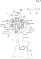
- the operating lever 41 includes one or more operating switches 42.
- the operating switches 42 are operated to operate functions of the working vehicle 1.
- a plurality of operating switches 42 are provided on the operating lever 41.
- the operating switches 42 include a push-button switch (tactile switch) operated by pressing an operation surface 42a, a slide switch operated by sliding the operation surface 42a, a dial-like switch (dial switch) such as a selector switch having a plurality of switching positions, and/or the like.
- the operating switches 42 are located on a rear surface of the operating portion 41b2 of the operating lever 41. That is, the plurality of operating switches 42 are located on the surface of the grip 41b that faces the operator's seat 4.
- the operating switches 42 include a first operating switch 42A, a second operating switch 42B, a third operating switch 42C, a fourth operating switch 42D, a fifth operating switch 42E, a sixth operating switch 42F, a seventh operating switch 42G, an eighth operating switch 42H, a ninth operating switch 421, a tenth operating switch 42J, an eleventh operating switch 42K, a twelfth operating switch 42L, and a thirteenth operating switch 42M.
- operating switches 42 is not limited to 13 and may be one or two, and the number and kinds of operating switches 42 are not limited.
- the operating device 40 may include, as the dial 44, another dial(s) 44 in addition to the first dial 45 and the second dial 46.
- the operating device 40 may include a third dial 47.
- the third dial 47 receives an instruction to operate the twenty-fifth function by being rotated in one direction (clockwise direction) and receives an instruction to operate the twenty-sixth function by being rotated in the other direction (counterclockwise direction).
- the operating device 40 may include a fourth dial 48 to operate the display 90.
- the fourth dial 48 can be rotated and pressed.
- the fourth dial 48 receives selection of an item displayed on the display 90 by being rotated in one direction (clockwise direction) or the opposite direction (counterclockwise direction). Furthermore, the fourth dial 48 receives determination (confirmation) of the selected item by being pressed.
- the operation actuator 49 is a switch to operate a predetermined function among the plurality of functions.
- the operating device 40 includes a plurality of the operation actuators 49.
- the operation actuators 49 are push-button switches (tactile switches) operated by being pressed.
- FIG. 9 is a plan view of the plurality of operation actuators 49. Operation surfaces 49a of the operation actuators 49 each have a substantially rectangular shape in plan view. As illustrated in FIGS. 5 , 6 , and 9 , the number of operation actuators 49 is 10.
- the sixth operation actuator 49F, the seventh operation actuator 49G, the eighth operation actuator 49H, the ninth operation actuator 491, and tenth operation actuator 49J are arranged in the vehicle body width direction to form a row (second row).
- the first row and the second row are arranged in the front-rear direction.
- the operation actuators 49 are provided in a third region 16c on the upper surface of the front portion of the armrest 16.
- the third region 16c is located rearward of the second region 16b, and the second region 16b and the third region 16c are arranged in the front-rear direction.
- the operating device 40 need only include at least any one of the operating lever 41, the dial(s) 44, and the operation actuator(s) 49 and may include another operation member(s) in addition to such one or more of the operating lever 41, the dial(s) 44, and the operation actuator(s) 49.
- the operating device 40 may include one or more swinging operation members 50 that are operated by being swung. Each swinging operation member 50 receives an instruction to operate the thirty-second function by being swung in one direction (forward) and receives an instruction to operate the thirty-third function by being swung in the other direction (rearward).
- the swinging operation members 50 are provided in a fourth region 16d on the upper surface of the front portion of the armrest 16.
- the fourth region 16d is located rearward of the third region 16c, and the third region 16c and the fourth region 16d are arranged in the front-rear direction. More specifically, the fourth region 16d is provided in a rear portion of the armrest 16 and is located forward of an elbow rest 16e on which the operator sitting on the operator's seat 4 places their elbow.
- the operating device 40 preferably includes as many swinging operation members 50 as the number of auxiliary valves 32. That is, in the present embodiment, four auxiliary valves 32 are provided, and therefore the operating device 40 includes four swinging operation members 50.
- the four swinging operation members 50 are arranged adjacent in the vehicle body width direction and can be swung about an axis extending in the substantially vehicle body width direction.
- the operating lever 41 need only be configured such that function(s) to be operated in accordance with an instruction received by the operating lever 41 vary(varies) depending on the operation mode.
- the operating lever 41 itself may be operable to change the operation mode and output different operation signals depending on the operation mode, so that function(s) to be operated in accordance with an instruction received by the operating lever 41 is/are changed.
- the operating lever 41 includes an operation control unit (not illustrated) including electric/electronic circuit(s) and/or program(s) stored in CPU(s) and/or the like, and causes the operation control unit to change the operation mode to change operation signal(s) corresponding to the operation(s).
- the operating lever 41 is configured such that function(s) to be operated in accordance with an instruction received by the operating lever 41 being pivoted vary(varies) depending on an operation mode selected via the selector 51. In other words, the operating lever 41 receives an instruction to operate a function that varies depending on the operation mode when pivoted. Additionally or alternatively, the operating lever 41 may receive an instruction to operate a function when an operating switch 42 is operated, based on the operation mode. In other words, the operating lever 41 may receive an instruction to operate a function that varies depending on the operation mode when the operating switch 42 is operated.
- the operation modes include first to fourth modes. That is, in the present embodiment, the storing unit 81 stores therein four standard tables (which may be hereinafter referred to as first to fourth standard tables) corresponding to the first to fourth modes.
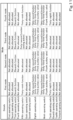
- FIG. 10 illustrates an example of a standard table. The following describes a relationship among the first to fourth modes, kinds of operations of the operating lever 41 in each of the operation modes, and instructions to operate functions received by the operations with reference to FIG. 10 .
- the operating lever 41 receives an instruction to operate the thirty-fifth function when pivoted forward. That is, in the first standard table, an operation signal which the operating lever 41 outputs when pivoted forward and the thirty-fifth function are associated. Therefore, in the first mode, when the operating lever 41 is pivoted forward, the controller 80 retracts the boom cylinder 35d to swing the boom 35b downward by controlling a control valve.
- the operating lever 41 receives an instruction to operate the thirty-seventh function when pivoted rightward. That is, in the first standard table, an operation signal which the operating lever 41 outputs when pivoted rightward and the thirty-seventh function are associated. Therefore, in the first mode, when the operating lever 41 is pivoted rightward, the controller 80 extends the bucket cylinder 35e so that the bucket 35c performs a dumping action by controlling a control valve.
- the operating lever 41 receives an instruction to operate the twenty-fifth function when the sixth operating switch 42F is operated. That is, in the first standard table, an operation signal output by the operating lever 41 when the sixth operating switch 42F is operated and the twenty-fifth function are associated. Therefore, in the first mode, when the sixth operating switch 42F is operated, the controller 80 extends the lift cylinder 30e to raise the working device 10 coupled to the lifting device 30 in response to the operation.
- the operating lever 41 receives an instruction to operate the thirty-second function or the thirty-third function when the eighth operating switch 42H is operated. That is, in the first standard table, an operation signal output by the operating lever 41 when the eighth operating switch 42H is slid in one direction and the thirty-second function are associated, and an operation signal output by the operating lever 41 when the eighth operating switch 42H is slid in the opposite direction and the thirty-third function are associated. Note that in the present embodiment, in the first mode, when the eighth operating switch 42H is operated, the controller 80 adjusts the flow rate of hydraulic fluid supplied to the hydraulic attachment 10a by controlling the first auxiliary valve 32a in response to the operation.
- the operating lever 41 receives an instruction to operate the fifteenth function or the sixteenth function when pivoted leftward. That is, in the second standard table, an operation signal which the operating lever 41 outputs when pivoted leftward and the fifteenth function or the sixteenth function are associated. Therefore, in the second mode, when the operating lever 41 is pivoted leftward, the controller 80 switches between the fifteenth function and the sixteenth function and switches the rotation direction of power output from the auxiliary transmission unit 20c between forward traveling and rearward traveling every time the operating lever 41 is pivoted.
- the operating lever 41 receives an instruction to operate the fourteenth function when the tenth operating switch 42J is operated. That is, in the second standard table, an operation signal output by the operating lever 41 when the tenth operating switch 42J is operated and the fourteenth function are associated. Therefore, in the second mode, when the tenth operating switch 42J is operated, the controller 80 switches the shuttle 20d to a neutral position by controlling the shuttle 20d to shut off power transmission in response to the operation.
- the number of traveling functions to be operated in accordance with an instruction that is received by the operating lever 41 in the second mode by the pivoting of the operating lever 41 or the operation of the plurality of operating switches 42 is larger than the number of work functions to be operated in accordance with an instruction that is received by the operating lever 41 in the second mode by the pivoting of the operating lever 41 or the operation of the plurality of operating switches 42. That is, the operating lever 41 in the second mode receives instructions to operate traveling functions preferentially over work functions.
- Functions of the working vehicle 1 to be operated in accordance with an instruction received by the operating lever 41 upon operation of the operating switches 42 in the third mode are different from functions of the working vehicle 1 to be operated in accordance with an instruction received by the operating lever 41 upon operation of the operating switches 42 in the second mode. Therefore, even when the switching between the second mode and the third mode is performed, it is possible to continuously perform control relating to travel by pivoting the operating lever 41. On the other hand, the switching between the second mode and the third mode makes it possible to operate different functions using the same operating switch 42.
- the operating lever 41 receives an instruction to operate the forty-second function when the fifth operating switch 42E is operated. That is, in the third standard table, an operation signal output by the operating lever 41 when the fifth operating switch 42E is operated and the forty-second function are associated. Therefore, in the third mode, when the fifth operating switch 42E is operated, the controller 80 controls the working vehicle 1 to perform a series of actions defined in advance in response to the operation. In particular, in the present embodiment, in the third mode, when the fifth operating switch 42E is operated, the controller 80 performs the entering action in response to the operation.
- the operating lever 41 receives an instruction to operate the forty-third function when the tenth operating switch 42J is operated. That is, in the third standard table, an operation signal output by the operating lever 41 when the tenth operating switch 42J is operated and the forty-third function are associated. Therefore, in the third mode, when the tenth operating switch 42J is operated, the controller 80 enables or disables the forty-third function in response to the operation, and in a case where the forty-third function is enabled, the controller 80 controls the working vehicle 1 based on an instruction signal output from the working device 10.
- the fourth mode is a mode in which instructions to operate functions of the working vehicle 1 are not received by the pivoting of the operating lever 41 and instructions to operate functions of the working vehicle 1 are received by the operation of the operating switches 42. That is, in a case where the operating lever 41 is pivoted in the fourth mode, the operating lever 41 does not receive instructions irrespective of operation direction and operation amount thereof. That is, in the fourth standard table, no functions are associated with the pivoting operations of the operating lever 41.
- the operating lever 41 receives instructions to operate functions identical to instructions to operate functions received in a case where the identical operating switches 42 are operated in the first mode.
- the functions allocated to the operations of the operating switches 42 are the same between the first mode and the fourth mode.
- the indicator 43 indicates that the changeover switch 53 is being operated.
- the indicator (lamp) 43 indicates that the changeover switch 53 is being operated, by blinking during a period where the changeover switch 53 is being operated and indicates that the changeover switch 53 is not operated by being lighted up during a period where the changeover switch 53 is not being operated. This allows the operator to easily know whether a current function to be operated in accordance with an instruction received by the operating switch 42 is a standard function or an expanded function. This can eliminate or reduce the likelihood that a standard function or an expanded function will be unintentionally operated, for example, in a case where the operator mistakenly operates the changeover switch 53.
- the light 42b may be provided on one or more of the operating switches 42 (the eighth operating switch 42H, the ninth operating switch 421, and the twelfth operating switch 42L) that are not tactile switches.
- the operating lever 41 in any one of the first to fourth modes receives an instruction to operate the thirty-second function or the thirty-third function of the fourth auxiliary valve 32d as an expanded function instead of the thirty-second function or the thirty-third function (standard function) of the second auxiliary valve 32b when the ninth operating switch 421 is operated during a period where the changeover switch 53 is being operated. That is, in the first to fourth expansion tables, an operation signal output by the operating lever 41 when the ninth operating switch 421 is slid in one direction and the thirty-second function of the fourth auxiliary valve 32d are associated, and an operation signal output by the operating lever 41 when the ninth operating switch 421 is slid in the opposite direction and the thirty-third function of the fourth auxiliary valve 32d are associated.
- the first category display frame 112b is displayed in a color that varies depending on the category into which the function corresponding to the icon 112a is classified has been described as an example, the first arrow portion 113 may also be displayed in a color that varies depending on the category additionally or alternatively.
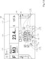
- the first changing screen M3 displays a schematic view 12A0 of the operating lever 41 including the operating switches 42, second allocation display portion(s) 121, a target switcher 125, a first category selector 126, and a first function selector 128.
- Each second allocation display portion 121 is a display image that represents a function allocated to the operating switch 42 as an icon that is a simple graphical representation of the function.
- the first function selector 128 is a display image that receives selection of a predetermined function among a plurality of functions classified into the category selected by the first category selector 126.
- the first function selector 128 displays a plurality of substantially rectangular images (third icon display portions 129) that indicate the functions as icons 129a that are simple graphical representation of the functions.
- the first function selector 128 displays the plurality of third icon display portions 129 such that the plurality of third icon display portions 129 are arranged in the left-right direction on the screen.
- This allows the operator to select a function which the operator wants to allocate by selecting any third icon display portion 129 (for example, by operating the fourth dial 48).
- the second display 90B receives selection of a predetermined function among the plurality of functions as an expanded function.
- the updater 80a updates (overwrites) the expansion table stored in the storing unit 81 by allocating, as an expanded function, a function corresponding to the selected third icon display portion 129 to the operating switch 42 corresponding to selected second icon display portion 122.
- the third icon display portion 129 includes a third type indicator portion 130 indicating the type of an operating switch 42, such as a tactile switch, a slide switch, or a dial switch, which is to be used to operate its corresponding function.
- the third type indicator portion 130 is a circular figure and is displayed in an upper right portion of the third icon display portion 129.
- the third type indicator portion 130 is displayed in green in a case where the corresponding function can be operated by a tactile switch, is displayed in blue in a case where the corresponding function can be operated by a slide switch, and is displayed in yellow in a case where the corresponding function can be operated by a dial switch.
- a check mark is added to the third type indicator portion 130 of the third icon display portion 129 indicative of a function that has been already allocated to an operation of any one of the operating switches 42, that is, a function that has been already allocated as an expanded function in the expansion table corresponding to the mode selected by the target switcher 125.
- the controller 80 causes the first light 42b1 to be lit in orange in a case where a function corresponding to the operating switch 42 in which the first light 42b1 is provided is any one of the first to third categories in the updated standard table and the changeover switch 53 is not being operated.
- the controller 80 causes the first light 42b1 to be lit in yellow in a case where a function corresponding to the operating switch 42 in which the first light 42b1 is provided is the fourth category in the updated standard table and the changeover switch 53 is not being operated.
- the controller 80 causes the first light 42b1 to be lit in blue in a case where a function corresponding to the operating switch 42 in which the first light 42b1 is provided is any one of the fifth to seventh categories in the updated standard table and the changeover switch 53 is not being operated.
- the controller 80 causes the first light 42b1 to be lit in purple in a case where a function corresponding to the operating switch 42 in which the first light 42b1 is provided is the eighth category in the updated standard table and the changeover switch 53 is not being operated.
- the controller 80 causes the first light 42b1 to be lit in green in a case where a function corresponding to the operating switch 42 in which the first light 42b1 is provided is the ninth category in the updated standard table and the changeover switch 53 is not being operated.
- a color in which the second light 42b2 is lit is white.
- the controller 80 changes a control signal output to the second light 42b2 based on the acquired expansion table, and in a case where the changeover switch 53 is not being operated and the second light 42b2 is lit, the second light 42b2 is lit in a color corresponding to the category into which an updated expanded function is classified.
- the controller 80 causes the second light 42b2 to be lit in orange in a case where a function corresponding to the operating switch 42 in which the second light 42b2 is provided is any one of the first to third categories in the updated expansion table and the changeover switch 53 is being operated.
- the controller 80 causes the second light 42b2 to be lit in yellow in a case where a function corresponding to the operating switch 42 in which the second light 42b2 is provided is the fourth category in the updated expansion table and the changeover switch 53 is being operated.
- the controller 80 causes the second light 42b2 to be lit in blue in a case where a function corresponding to the operating switch 42 in which the second light 42b2 is provided is any one of the fifth to seventh categories in the updated expansion table and the changeover switch 53 is being operated.
- the controller 80 causes the second light 42b2 to be lit in purple in a case where a function corresponding to the operating switch 42 in which the second light 42b2 is provided is the eighth category in the updated expansion table and the changeover switch 53 is being operated.
- the controller 80 causes the second light 42b2 to be lit in green in a case where a function corresponding to the operating switch 42 in which the second light 42b2 is provided is the ninth category in the updated expansion table and the changeover switch 53 is being operated.
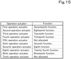
- the updater 80a can update functions allocated to the operation actuators 49 to different functions. Specifically, as illustrated in FIG. 15 , the storing unit 81 stores therein a table (operation table) in which operation signals of the operation actuators 49 and functions are associated, as with the standard table and the expansion table of the operating switches 42. The controller 80 acquires the operation table from the storing unit 81 and controls (performs) a function based on an operation signal output from the operation actuator 49 and the operation table. FIG. 15 illustrates an example of the operation table. Furthermore, the updater 80a (the controller 80) updates (overwrites) the operation table stored in the storing unit 81 based on a function whose update has been received by the second display 90B.
- a table operation table
- an operation signal output by the second operation actuator 49B when the second operation actuator 49B is operated and the eighteenth function are associated, and the second operation actuator 49B receives an instruction to operate the eighteenth function when operated.
- the controller 80 enables or disables the eighteenth function in response to the operation, and in a case where the eighteenth function is enabled, the controller 80 switches between 2WD and the 4WD equal speed state by controlling the front transmission unit 20f based on the vehicle speed and the steering angle of the steering device.
- the third operation actuator 49C receives an instruction to operate the twentieth function when operated. Accordingly, in a case where the updater 80a has not updated the initial table, when the third operation actuator 49C is operated, the controller 80 fixes (directly couples) the rear wheel differential 21R based on an operator's operation in response to the operation.
- no function is associated with an operation signal output by the fifth operation actuator 49E when the fifth operation actuator 49E is operated, and the fifth operation actuator 49E does not receive an instruction to operate a function even when operated until a function is associated with the operation signal output by the fifth operation actuator 49E by updating the operation table by the updater 80a.
- the fifth operation actuator 49E receives an instruction to operate the associated function when operated.
- an operation signal output by the sixth operation actuator 49F when the sixth operation actuator 49F is operated and the seventh function are associated, and the sixth operation actuator 49F receives an instruction to operate the seventh function when operated.
- the controller 80 enables or disables the seventh function in response to the operation, and in a case where the seventh function is enabled, the controller 80 shuts off transmission of power to the traveling device 3 by switching the hydraulic clutch of the shuttle 20d to a neutral position when the vehicle speed becomes less than a predetermined value as a result of an operation of the brake pedal.
- an operation signal output by the eighth operation actuator 49H when the eighth operation actuator 49H is operated and the twenty-fourth function are associated, and the eighth operation actuator 49H receives an instruction to operate the twenty-fourth function when operated. Accordingly, in a case where the updater 80a has not updated the initial table, when the eighth operation actuator 49H is operated, the controller 80 enables or disables the twenty-fourth function in response to the operation, and in a case where the twenty-fourth function is enabled, the controller 80 switches power transmission to the PTO shaft 22 by controlling the PTO power transmission unit 20e in accordance with the height of the working device 10.
- an operation signal output by the ninth operation actuator 49I when the ninth operation actuator 49I is operated and the nineteenth function are associated, and the ninth operation actuator 49I receives an instruction to operate the nineteenth function when operated. Accordingly, in a case where the updater 80a has not updated the initial table, when the ninth operation actuator 49I is operated, the controller 80 switches to the 4WD speed-increasing state by controlling the front transmission unit 20f in response to the operation.
- no function is associated with an operation signal output by the tenth operation actuator 49J when the tenth operation actuator 49J is operated, and the tenth operation actuator 49J does not receive an instruction to operate a function even when operated until a function is associated with the operation signal output by the tenth operation actuator 49J by updating the operation table by the updater 80a.
- the tenth operation actuator 49J receives an instruction to operate the associated function when operated.
- the second display 90B displays the second changing screen M4 such as the one illustrated in FIG. 16 and receives input of allocation of an updated function.
- FIG. 16 illustrates an example of the second changing screen M4.
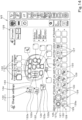
- the second changing screen M4 displays a schematic view 140 of the operation actuators 49, third allocation display portion(s) 141, a second category selector 144, and a second function selector 146.
- Each third allocation display portion 141 is a display image that displays a function allocated to the operation actuator 49 as an icon that is a simple graphical representation of the function. In the example illustrated in FIG.
- the third allocation display portion 141 includes a substantially rectangular image (the fourth icon display portion 142) where an icon 142a is displayed and a third arrow portion 143 indicating an operation actuator 49 corresponding to the icon 142a.
- An outer frame (a third category display frame 142b) that indicates the outer frame of the fourth icon display portion 142 and surrounds the icon 142a may be displayed in a color that varies depending on the category into which a function corresponding to the icon 142a of the fourth icon display portion 142 is classified, as with the first category display frame 112b.
- the third arrow portion 143 may also be displayed in a color that varies depending on the category in addition or instead of this.
- the icon 142a is not displayed in the third allocation display portion 141 of the operation actuator 49 (e.g., the fifth operation actuator 49E and the tenth operation actuator 49J) to which no function is allocated.
- the operator selects the operation actuator 49 to which the operator wants to allocate a new function (updated function) by selecting any fourth icon display portion 142 (for example, by operating the fourth dial 48).
- the second display 90B receives selection of a predetermined operation actuator 49 among the plurality of operation actuators 49.
- the second category selector 144 is a display image that receives selection of the category (any one of the first to ninth categories) into which the plurality of functions concerning the working vehicle 1 are classified.
- the second category selector 144 displays a plurality of substantially rectangular images (category display portions 145) that display the categories as icons 145a.
- the second category selector 144 displays the plurality of category display portions 145 such that the plurality of category display portions 145 are arranged in the left-right direction on the screen.
- the operator selects the category into which a function which the operator wants to allocate is classified by selecting any category display portion 145 (for example, by operating the fourth dial 48). In this way, the second display 90B receives selection of a predetermined category among the plurality of categories.
- the second function selector 146 is a display image that receives selection of a predetermined function among a plurality of functions classified into the category selected by the second category selector 144.
- the second function selector 146 displays a plurality of substantially rectangular images (fifth icon display portions 147) that display the functions as icons 147a.
- the second function selector 146 displays the plurality of fifth icon display portions 147 such that the plurality of fifth icon display portions 147 are arranged in the left-right direction on the screen.
- the operation actuators 49 are tactile switches, and therefore the second function selector 146 displays at least a function that can be operated by a tactile switch among the plurality of functions classified into the category selected by the second category selector 144.
- the second function selector 146 displays a function that cannot be operated by a tactile switch among the plurality of functions classified into the category selected by the second category selector 144 in an unselectable manner by graying out the function or hides the function.
- a mark 148 indicating whether or not a function has been already allocated to an operation of one of the operation actuators 49, that is, has been already allocated as an initial function or an updated function in the operation table is provided in the fifth icon display portion 147.
- the mark 148 is a circular figure, and a check mark is added to the fifth icon display portion 147 of a function that has been already allocated as an initial function or an updated function.
- the operator selects the fifth icon display portion 147 of a function which the operator wants to allocate by selecting any fifth icon display portion 147 (for example, by operating the fourth dial 48).
- the second display 90B receives selection of a predetermined function among the plurality of functions as an updated function.
- the updater 80a updates (overwrites) the operation table stored in the storing unit 81 by allocating, as an updated function, a function corresponding to the selected fifth icon display portion 147 to the operation actuator 49 corresponding to the selected fourth icon display portion 142.
- the second changing screen M4 illustrated in FIG. 16 is merely an example, and the screen and a method of allocating an updated function in the operation table are not limited to the above example.
- each of the operation actuators 49 has an icon 49a1 representing an initial function.
- the icon 49a1 is a figure that is a simple graphical representation of an initial function and is provided in a central portion of the operation surface 49a of the operation actuator 49.
- each of the operation actuators 49 includes a first indicator lamp 49b1, a second indicator lamp 49b2, and third indicator lamp(s) 49b3.
- the first indicator lamp 49b1, the second indicator lamp 49b2, and the third indicator lamp 49b3 are light emitting devices that emit light.
- the first indicator lamp 49b1, the second indicator lamp 49b2, and the third indicator lamp 49b3 each include one or more light sources (e.g., LEDs).
- the controller 80 turns on the first indicator lamp 49b1, the second indicator lamp 49b2, and the third indicator lamp 49b3 during a period where an operation instruction can be received, in other words, during a period where the working vehicle 1 is in operation.
- controller 80 may turn off the first indicator lamp 49b1, the second indicator lamp 49b2, and the third indicator lamp 49b3 in a case where an error is occurring in a function corresponding to the operation actuator 49 or in a case where execution of a function is restricted in accordance with the operation mode of the operating lever 41.
- the following describes colors in which the first indicator lamp 49b1, the second indicator lamp 49b2, and the third indicator lamp 49b3 are lit.
- the first indicator lamp 49b1 changes the manner in which it provides an indication depending on the category to which a function (updated function) updated by the updater 80a belongs.
- the first indicator lamp 49b1 is lit in a color that varies depending on the category to which the function updated by the updater 80a belongs. This allows the operator to easily know the category of the function updated by the updater 80a. This can prevent or reduce occurrence of an erroneous operation even in a case where function(s) to be operated in accordance with an instruction received by the operation actuator 49 is/are updated.
- the controller 80 causes the first indicator lamp 49b1 to be lit in orange in a case where an updated function corresponding to the operation actuator 49 where the first indicator lamp 49b1 is provided is any one of the first to third categories in the updated operation table.
- the controller 80 causes the first indicator lamp 49b1 to be lit in yellow in a case where the updated function corresponding to the operation actuator 49 where the first indicator lamp 49b1 is provided is the fourth category in the updated operation table.
- the controller 80 causes the first indicator lamp 49b1 to be lit in blue in a case where the updated function corresponding to the operation actuator 49 where the first indicator lamp 49b1 is provided is any one of the fifth to seventh categories in the updated operation table.
- the controller 80 causes the first indicator lamp 49b1 to be lit in purple in a case where the function corresponding to the operation actuator 49 where the first indicator lamp 49b1 is provided is the eighth category in the updated operation table.
- the controller 80 causes the first indicator lamp 49b1 to be lit in green in a case where the updated function corresponding to the operation actuator 49 where the first indicator lamp 49b1 is provided is the ninth category in the updated operation table.
- the second indicator lamp 49b2 changes the manner in which it provides an indication depending on whether a function allocated to the operation actuator 49 is enabled or disabled. Specifically, the controller 80 changes a control signal output to the second indicator lamp 49b2 of the operation actuator 49 depending on whether a function allocated to the operation actuator 49 is enabled or disabled. In the present embodiment, the second indicator lamp 49b2 is lit in white in a case where function(s) to be operated in accordance with a received instruction is/are disabled. On the other hand, the second indicator lamp 49b2 is lit in green in a case where the function(s) to be operated in accordance with a received instruction is/are enabled.
- the third indicator lamp 49b3 is lit in white.
- two third indicator lamps 49b3 are provided on each of the operation actuators 49, and the two third indicator lamps 49b3 are not lit in a color other than white.
- the controller 80 may cause the third indicator lamps 49b3 to be lit in a color such as red or blink in a case where an error is occurring in a function corresponding to the operation actuator 49 where the third indicator lamps 49b3 are provided.
- the first indicator lamp 49b1, the second indicator lamp 49b2, and the third indicator lamps 49b3 are located at corners of the operation surface 49a.
- the first indicator lamp 49b1 is located in a front left portion of the operation surface 49a
- the second indicator lamp 49b2 is located in a front right portion of the operation surface 49a.
- the third indicator lamps 49b3 are located in a rear left portion and rear right portion of the operation surface 49a.
- the first indicator lamp 49b1 extends leftward from the central portion of the front edge of the operation surface 49a in the left-right direction and reaches the central portion of the left edge of the operation surface 49a in the front-rear direction. That is, the first indicator lamp 49b1 has a substantially inverse L shape.
- the second indicator lamp 49b2 extends rightward from the central portion of the front edge of the operation surface 49a in the left-right direction and reaches the central portion of the right edge of the operation surface 49a in the front-rear direction. That is, the second indicator lamp 49b2 has a substantially L shape.
- the third indicator lamp 49b3 located in the rear left portion of the operation surface 49a extends leftward from the central portion of the rear edge of the operation surface 49a in the left-right direction and reaches the central portion of the left edge of the operation surface 49a in the front-rear direction. That is, the third indicator lamp 49b3 located in the rear left portion of the operation surface 49a has a substantially L shape.
- the third indicator lamp 49b3 located in the rear right portion of the operation surface 49a extends rightward from the central portion of the rear edge of the operation surface 49a in the left-right direction and reaches the central portion of the right edge of the operation surface 49a in the front-rear direction. That is, the third indicator lamp 49b3 located in the rear right portion of the operation surface 49a has a substantially inverse L shape.
- the first indicator lamp 49b1, the second indicator lamp 49b2, and the third indicator lamps 49b3 are positioned apart from one another. Specifically, a right end of the first indicator lamp 49b1 and a left end of the second indicator lamp 49b2 are positioned apart from each other in the left-right direction. A rear end of the first indicator lamp 49b1 and a front end of the third indicator lamp 49b3 located in the rear left portion are positioned apart from each other in the front-rear direction. A rear end of the second indicator lamp 49b2 and a front end of the third indicator lamp 49b3 located in the rear right portion are positioned apart from each other in the front-rear direction. A right end of the third indicator lamp 49b3 located in the rear left portion and a left end of the third indicator lamp 49b3 located in the rear right portion are positioned apart from each other in the left-right direction.
- first indicator lamp 49b1, the second indicator lamp 49b2, and the third indicator lamps 49b3 are positioned apart from one another in the above embodiment, the first indicator lamp 49b1, the second indicator lamp 49b2, and the third indicator lamps 49b3 may be positioned close to one another as long as indications (e.g., on and off) provided by the first indicator lamp 49b1, the second indicator lamp 49b2, and the third indicator lamps 49b3 are distinguishable.
- the dial 44 can receive an operation to change a control parameter of a function.
- the dial 44 can receive an instruction to operate a function to change a parameter of a function such as the tenth function to change the first prime mover rotational speed of the ninth function or the twelfth function to change the second prime mover rotational speed of the eleventh function.
- the controller 80 changes a control parameter of each function stored in the storing unit 81 based on an operation signal output from the dial 44.
- the first dial (first function operation actuator) 45 is an operation member (a physical dial switch in the present embodiment) to select among a plurality of functions by a rotating operation. Functions that can be selected via (by the operation) of the first dial 45 (candidate functions) are stored in advance in the storing unit 81.
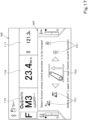
- the controller 80 acquires an operation signal output from the first dial 45 and causes a third changing screen M5 to be displayed on the display 90 (the first display 90A in the present embodiment), as illustrated in FIG. 17.
- FIG. 17 illustrates an example of the third changing screen M5 and the information display screen M2.
- the first display 90A displays the third changing screen M5 together with the information display screen M2, as with the operation display screen M1.
- the third changing screen M5 displays the functions that can be selected by the operation of the first dial 45.
- the display 90 displays a function selected via the first dial 45 and other functions in different display forms.
- the third changing screen M5 displays a selected function display portion 150 and candidate function display portions 151.
- the selected function display portion 150 is an image that displays one function selected via the first dial 45 as an icon.
- Each candidate function display portion 151 is an image that displays another function as an icon.
- the candidate function display portions 151 are provided on one of opposite sides (left side) in the left-right direction and the other of the opposite sides (right side) in the left-right direction of the selected function display portion 150.
- the third changing screen M5 displays, in the selected function display portion 150, one of the functions that can be selected by the operation of the first dial 45 and, as the first dial 45 is operated, displays, in the selected function display portion 150, one of the functions displayed in the candidate function display portions 151 instead of the function previously displayed in the selected function display portion 150. That is, the function displayed in the selected function display portion 150 is sequentially changed as the first dial 45 is operated.
- a state where the twenty-seventh function is being selected is illustrated.
- the candidate function display portions 151 are provided on one of the opposite sides (left side) and the other of the opposite sides (right side) of the selected function display portion 150 in the left-right direction and the candidate function display portions 151 display all the other functions except for the one function displayed in the selected function display portion 150 among the functions that can be selected by the operation of the first dial 45, in the example of the third changing screen M5 illustrated in FIG. 17 .
- the second dial (second function operation actuator) 46 is an operation member (a physical dial switch in the present embodiment) that changes a control parameter of a function selected by the first dial 45 by a rotating operation.
- the display 90 (the first display 90A) can display the control parameter changed by the second dial 46.
- the controller 80 confirms one function selected by an operation of the first dial 45 as a target function whose parameter is to be changed.
- the first display 90A shifts the display from the third changing screen M5 to a fourth changing screen M6 indicative of a control parameter, as illustrated in FIG. 18.
- FIG. 18 illustrates an example of the fourth changing screen M6 and the information display screen M2. Note that as illustrated in FIG. 18 , the first display 90A displays the fourth changing screen M6 together with the information display screen M2, as with the operation display screen M1 and the third changing screen M5.
- the fourth changing screen M6 includes a target function display portion 160 and a parameter display portion 161.
- the target function display portion 160 is an image that displays a target function whose parameter is to be changed as an icon.
- the parameter display portion 161 is an image that displays a candidate (candidate parameter) of a changed parameter in response to an operation of the second dial 46.
- the parameter display portion 161 displays the candidate parameter as a numerical value.
- a display form of the parameter display portion 161 is not limited to a numerical value as long as the candidate parameter can be displayed, and can be, for example, a bar-shaped meter shape whose length varies depending on the candidate parameter.
- the controller 80 confirms the candidate parameter displayed in the parameter display portion 161, for example, in a case where a predetermined period has elapsed from the operation of the second dial 46 or in a case where the first dial 45 is operated.
- the controller 80 changes the control parameter of the function that is stored in the storing unit 81 and displayed in the target function display portion 160 based on the confirmed candidate parameter.
- a method of confirming the candidate parameter displayed in the parameter display portion 161 is not limited to the above method.
- the controller 80 may confirm the candidate parameter in response to the pressing operation of the second dial 46.
- the controller 80 may confirm the candidate parameter in response to an operation of this operation member.
- the axial direction of a rotary axis L1 of the first dial 45 is different from the axial direction of a rotary axis L2 of the second dial 46.
- the axial direction of the rotary axis L1 of the first dial 45 may be orthogonal to the axial direction of the rotary axis L2 of the second dial 46. This allows the operator to easily distinguish which dial 44 is operated to select a function and which dial 44 is operated to select a parameter. This can achieve a speedy operation of a parameter of a function of the working vehicle 1.
- the rotary axis L1 of the first dial 45 extends in the up-down direction
- the rotary axis L2 of the second dial 46 extends in a substantially vehicle body width direction.
- the operator can rotate the first dial 45 in the clockwise direction about the axis thereof in the up-down direction or can rotate the first dial 45 in the counterclockwise direction about the axis thereof in the up-down direction.
- the operator can rotate the second dial 46 in the forward direction or the rearward direction about the axis thereof in the vehicle body width direction.
- first dial 45 and the second dial 46 are adjacent to each other in the front-rear direction. This allows the operator to speedily operate the second dial 46 by moving their wrist while keeping the posture to operate the first dial 45.
- the axis direction and position of the rotary axis L1 of the first dial 45 and the axis direction and position of the rotary axis L2 of the second dial 46 are not limited to the above directions and positions.
- the first dial 45 and the second dial 46 may be adjacent to each other in the vehicle body width direction.
- the controller 80 may include a changer 80b.
- the changer 80b changes the functions that can be selected via (by the operation of) the first dial 45 (candidate functions) among the plurality of functions.
- the changer 80b includes electric/electronic circuit(s) provided in the controller 80 and/or program(s) stored in CPU(s) and/or the like.
- the updater 80a (the controller 80) updates (overwrites) the candidate functions stored in the storing unit 81 based on function(s) which the display 90 (the second display 90B in the present embodiment) receives on a fifth changing screen M7.
- the second display 90B displays the fifth changing screen M7 such as the one illustrated in FIG. 19 and receives selection of a candidate function.
- FIG. 19 illustrates an example of the fifth changing screen M7.
- the fifth changing screen M7 displays a selection display portion 170, a third category selector 173, and a third function selector 175.
- the selection display portion 170 is a display image that displays a function that is being selected as a candidate function as an icon 171a that is a simple graphical representation of the function.
- the operator selects a candidate function to be replaced with a new candidate function by selecting any sixth icon display portion 171 (for example, by operating the fourth dial 48).
- the third category selector 173 is a display image that receives selection of one of the categories (any one of the first to ninth categories) into which the plurality of functions concerning the working vehicle 1 are classified.
- the third category selector 173 displays a plurality of substantially rectangular images (category display portions 174) that indicate the categories as icons 174a.
- the third category selector 173 displays the plurality of category display portions 174 such that the plurality of category display portions 174 are arranged in the left-right direction on the screen.
- the operator selects a category into which a function which the operator wants to allocate is classified by selecting any category display portion 174 (for example, by operating the fourth dial 48). In this way, the second display 90B receives selection of a predetermined category among the plurality of categories.
- the third function selector 175 is a display image that receives selection of a predetermined function among a plurality of functions classified into the category selected by the third category selector 173.
- the third function selector 175 displays a plurality of substantially rectangular images (seventh icon display portions 176) that indicate the functions as icons 176a.
- the third function selector 175 displays the plurality of seventh icon display portions 176 such that the plurality of seventh icon display portions 176 are arranged in the left-right direction on the screen.
- the plurality of seventh icon display portions 176 display functions such as the third function, the sixth function, the tenth function, the twelfth function, and/or the twenty-fifth to twenty-eighth functions as the icons 176a.
- the operator selects a seventh icon display portion 176 of a function which the operator wants to allocate by selecting the seventh icon display portion 176 (for example, by operating the fourth dial 48).
- the second display 90B receives selection of a predetermined function among the plurality of functions as a candidate function.
- the changer 80b updates (overwrites) the candidate functions stored in the storing unit 81 by replacing the function corresponding to the selected sixth icon display portion 171 with the function corresponding to the selected seventh icon display portion 176 as a candidate function.
- the fifth changing screen M7 illustrated in FIG. 19 is merely an example, and the screen and a method of allocating a candidate function are not limited to the above example.
- the first function operation actuator 45 and the second function operation actuator 46 are physical dial switches
- the first function operation actuator 45 may include one or more tactile switches and/or the like or may be another operation actuator as long as the first function operation actuator 45 is an operation actuator to select among a plurality of functions.
- the first function operation actuator 45 may be a display image that is displayed on the display screen (display) 90 and receives a selecting operation.
- the selected function display portion 150 and the candidate function display portions 151 illustrated in FIG. 17 also serve as the first function operation actuator 45.
- the third changing screen M5 displays, in the selected function display portion 150, a function displayed in one of the candidate function display portions 151 instead of the function displayed in the selected function display portion 150 in response to the swiping operation.
- switching of the operation mode is not limited to a selecting operation using the selector 51.
- the operation mode may be switched by changing the shape of the operating lever 41 instead of or in addition to the operation of the selector 51. This makes it possible to perform various kinds of control of the working vehicle 1 by changing the form of a switcher 55 even in a case where only a single operating lever 41 is provided. This makes it unnecessary for the operator to switch the operating lever 41 to another one every time an environment where the working vehicle 1 travels or work content changes, thus eliminating or reducing the likelihood that the operator will operate a wrong switch or a wrong lever.
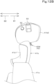
- the operating lever 41 includes the switcher 55, as in a variation illustrated in FIG. 20.
- FIG. 20 illustrates the operating lever 41 according to the variation as viewed from the operator's seat 4.
- the switcher 55 is a member that couples the grip 41b and the base portion 41a.
- the switcher 55 switches between a first form 55A in which the angle of the grip 41b with respect to the base portion 41a (e.g., the angle between a reference line L3 extending in a direction in which the base portion 41a illustrated in FIG. 20 extends and a reference line L4 extending in a direction in which the grip 41b extends) is a first angle ⁇ 1 and a second form 55B in which the angle is a second angle ⁇ 2 different from the first angle ⁇ 1.
- the second angle ⁇ 2 is an angle larger than the first angle ⁇ 1.
- the grip 41b extends from the switcher 55 along the direction in which the base portion 41a extends, and the operating lever 41 extends in a substantially linear manner.
- the grip 41b extends from the switcher 55 inward or outward along the width direction, and the operating lever 41 is bent at an intermediate portion.
- the switcher 55 includes a first bracket 56, a second bracket 57, a rotary shaft 58, and a form keeper 59, and as illustrated in FIG. 21 , the switcher 55 includes a form detector 60.
- the first bracket 56 is provided at a proximal end of the grip 41b.
- the second bracket 57 is provided at a distal end of the base portion 41a and rotatably supports the first bracket 56 via the rotary shaft 58.
- the rotary shaft 58 extends in the front-rear direction.
- the first bracket 56 and the second bracket 57 have an insertion hole through which the rotary shaft 58 is inserted, and the grip 41b rotates about the rotary shaft 58 and thus the angle of the grip 41b with respect to the base portion 41a can be changed.
- the form keeper 59 is configured to keep the state of the first form 55A and the state of the second form 55B.
- the form keeper 59 includes a lock member 59a and is attached to the second bracket 57.
- the lock member 59a is a lock ball and keeps the state of the first form 55A and the state of the second form 55B by being engaged with a lock recess 56a provided in the first bracket 56.
- the lock member 59a is disengaged from the first recess 56a1 and is engaged with the second recess 56a2. In this way, the form keeper 59 can keep the state of the first form 55A and the state of the second form 55B.
- the structure of the form keeper 59 is not limited to the above structure as long as the form keeper 59 can keep the state of the first form 55A and the state of the second form 55B.
- the form detector 60 is a detection sensor that detects whether the operating lever 41 is in the first form 55A or in the second form 55B.
- the form detector 60 is, for example, a limit switch, and detects whether the operating lever 41 is in the first form 55A or in the second form 55B by detecting the position of the grip 41b with respect to the base portion 41a.
- the form detector 60 is connected to the controller 80 and outputs a detection signal to the controller 80.
- the controller 80 thus switches the operating lever 41 into the first mode in a case where the operating lever 41 is in the first form 55A and switches the operating lever 41 into the second mode in a case where the operating lever 41 is in the second form 55B.
- the operating lever 41 is configured such that function(s) of the working vehicle 1 to be operated in accordance with an instruction received by the operating lever 41 can be changed depending on whether the switcher 55 is in the first form 55A or in the second form 55B. Furthermore, the operating lever 41 is configured such that function(s) of the working vehicle 1 to be operated in accordance with an instruction received by pivoting of the operating lever 41 can be changed depending on whether the switcher 55 is in the first form 55A or in the second form 55B.
- the operating lever 41 is changed in shape and the operation mode is switched based on such an operation, it is only necessary that the operating lever 41 can be switched between at least the first mode and the second mode. Furthermore, in a case where the operation mode is switched into another mode such as the third mode or the fourth mode in addition to the first mode and the second mode, the operation mode can be switched between the first mode and the fourth mode and can be switched between the second mode and the third mode using the selector 51.
- the standard map and the expansion map of the third mode of the above embodiment may be used as the standard map and the expansion map of the second mode.
- the operating lever 41 is configured such that function(s) of the working vehicle 1 to be operated in accordance with an instruction received by the operation of the operating switch 42 may be changed depending on whether the switcher 55 is in the first form 55A or in the second form 55B. Furthermore, since the indicator 43 changes the manner in which the indicator 43 provides an indication depending on the operation mode as described above, the indicator 43 changes the manner in which it provides an indication depending on whether the switcher 55 is in the first form 55A or in the second form 55B. More specifically, the indicator 43 changes its color depending on whether the switcher 55 is in the first form 55A or in the second form 55B.
- Operating devices 40 for working vehicles 1, assistance apparatuses 100 for working vehicles 1, and working vehicles 1 as has been described achieve one or more of the following effects.
- An operating device 40 for a working vehicle 1 including an operating lever 41 to operate functions of the working vehicle 1, and a selector 51 to select an operation mode of the operating lever 41, wherein the operating lever 41 is configured such that one or more functions of the working vehicle 1 to be operated in accordance with an instruction received by the operating lever 41 vary depending on the operation mode selected via the selector 51.
- various functions of the working vehicle 1 can be operated by operation of the operating lever 41 by switching the operation modes via the selector 51, even though only a single operating lever 41 is provided.
- This makes it unnecessary for the operator to switch the operating lever 41 to another one every time an environment where the working vehicle 1 travels or work content changes, thus eliminating or reducing the likelihood that the operator will operate a wrong switch or lever.
- it is unnecessary to increase the number of operating levers 41 in accordance with types of functions of the working vehicle 1. This can reduce the number of operation members on the operating device 40. It follows that it is possible to not only improve operability of the entire operating device 40, but also eliminate or reduce the likelihood that the operating lever 41 will hinder a field of view of the operator.
- a function to be operated in accordance with an instruction received by the operating lever 41 being pivoted can be freely changed by selecting an operation mode using the selector 51. This makes it possible to reduce the number of operation members on the operating device 40. It is therefore possible to not only secure a sufficient space for installation of the operating lever 41, but also eliminate or reduce the likelihood that the operation member will interfere with another operation member(s). It follows that it is possible to improve operability of the entire operating device 40.
- a plurality of the operation modes include a first mode in which at least one or more work functions relating to work among the functions of the working vehicle 1 are operated and a second mode in which at least one or more traveling functions relating to travel among the functions of the working vehicle 1 are operated, the operating lever 41 is operable to, in the first mode, receive an instruction to operate the one or more work functions by being pivoted, and the operating lever 41 is operable to, in the second mode, receive an instruction to operate the one or more traveling functions by being pivoted.
- the operator can successively operate a work operation and a traveling operation using the operating lever 41 without switching the operating lever 41 to another one.
- the operating device 40 according to item A3, wherein the operating lever 41 includes at least one operating switch 42, and is configured such that a function of the working vehicle 1 to be operated in accordance with an instruction received by the operating lever 41 by an operation of the at least one operating switch 42 varies depending on the operation mode selected via the selector 51.
- control concerning travel can be performed by pivoting of the operating lever 41 continuously before and after switching between the second mode and the third mode, whereas different actions can be performed by operation of the same operating switch 42 by switching between the second mode and the third mode. Therefore, for example, in a case where the working vehicle 1 travels into and out of the agricultural field, content of an action concerning work and/or travel corresponding to an operation of the operating switch 42 can be changed by switching between the second mode and the second mode while continuing travelling. It is therefore possible to increase versatility of the operating lever 41.
- the operator can easily know a current operation mode selected by an operation of the selector 51.
- the operator can easily check the indicator 43 when operating the operating lever 41.
- the operator can know the current operation mode selected by an operation of the selector 51 at a glance.
- a working vehicle 1 including a vehicle body 2, an operator's seat 4 on the vehicle body 2, and the operating device 40 according to any one of items A1 to A11 provided in the vicinity of the operator's seat 4.
- the operator can easily know the state of the operating lever 41 due to the indicator 43 in addition to the form of the switcher 55.
- a working vehicle 1 including a vehicle body 2, an operator's seat 4 on the vehicle body 2, and the operating device 40 according to any one of items E1 to E7 provided in the vicinity of the operator's seat 4.
Landscapes
- Engineering & Computer Science (AREA)
- Chemical & Material Sciences (AREA)
- Combustion & Propulsion (AREA)
- Transportation (AREA)
- Mechanical Engineering (AREA)
- Lifting Devices For Agricultural Implements (AREA)
- Transplanting Machines (AREA)
Applications Claiming Priority (3)
| Application Number | Priority Date | Filing Date | Title |
|---|---|---|---|
| JP2022210889A JP2024094118A (ja) | 2022-12-27 | 2022-12-27 | 作業車両の支援装置、及び作業車両 |
| JP2022210890A JP7826183B2 (ja) | 2022-12-27 | 2022-12-27 | 作業車両の支援装置、及び作業車両 |
| JP2022210891A JP7826184B2 (ja) | 2022-12-27 | 2022-12-27 | 作業車両の操作装置、及び作業車両 |
Publications (2)
| Publication Number | Publication Date |
|---|---|
| EP4393748A2 true EP4393748A2 (de) | 2024-07-03 |
| EP4393748A3 EP4393748A3 (de) | 2024-11-27 |
Family
ID=89190761
Family Applications (1)
| Application Number | Title | Priority Date | Filing Date |
|---|---|---|---|
| EP23215684.4A Pending EP4393748A3 (de) | 2022-12-27 | 2023-12-11 | Hilfsvorrichtung für arbeitsfahrzeug, betriebsvorrichtung für arbeitsfahrzeug und arbeitsfahrzeug |
Country Status (2)
| Country | Link |
|---|---|
| US (1) | US20240208329A1 (de) |
| EP (1) | EP4393748A3 (de) |
Families Citing this family (9)
| Publication number | Priority date | Publication date | Assignee | Title |
|---|---|---|---|---|
| USD1059418S1 (en) * | 2021-12-23 | 2025-01-28 | Stryker Corporation | Housing for a display screen |
| USD1059368S1 (en) * | 2021-12-23 | 2025-01-28 | Stryker Corporation | Housing for a display screen |
| USD1062768S1 (en) * | 2023-03-13 | 2025-02-18 | Deere & Company | Display screen or portion thereof with icon |
| USD1063960S1 (en) * | 2023-03-13 | 2025-02-25 | Deere & Company | Display screen or portion thereof with graphical user interface |
| USD1062767S1 (en) * | 2023-03-13 | 2025-02-18 | Deere & Company | Display screen or portion thereof with graphical user interface |
| USD1063980S1 (en) * | 2023-03-13 | 2025-02-25 | Deere & Company | Display screen or portion thereof with transitional graphical user interface |
| USD1063961S1 (en) * | 2023-03-13 | 2025-02-25 | Deere & Company | Display screen or portion thereof with transitional icon |
| USD1062779S1 (en) * | 2023-03-13 | 2025-02-18 | Deere & Company | Display screen or portion thereof with icon |
| USD1081694S1 (en) * | 2023-11-22 | 2025-07-01 | Shenzhen Hanyang Technology Co., Ltd. | Display screen or portion thereof with animated graphical user interface |
Citations (2)
| Publication number | Priority date | Publication date | Assignee | Title |
|---|---|---|---|---|
| JP2017091061A (ja) | 2015-11-05 | 2017-05-25 | ヤンマー株式会社 | 作業車両 |
| JP2018030502A (ja) | 2016-08-25 | 2018-03-01 | 三菱マヒンドラ農機株式会社 | トラクタ |
Family Cites Families (18)
| Publication number | Priority date | Publication date | Assignee | Title |
|---|---|---|---|---|
| JPH08117396A (ja) * | 1994-10-25 | 1996-05-14 | Sammy Ind Co Ltd | 弾球遊技機及び弾球遊技機における遊技球の飛距離表示方法 |
| US6085846A (en) * | 1999-07-01 | 2000-07-11 | Automatic Depth Control, Llc | Potentiometer-based gauge wheel device positioning system and method |
| US6216794B1 (en) * | 1999-07-01 | 2001-04-17 | Andrew F. Buchl | Joystick control for an automatic depth control system and method |
| US6662881B2 (en) * | 2001-06-19 | 2003-12-16 | Sweepster, Llc | Work attachment for loader vehicle having wireless control over work attachment actuator |
| JP2003252230A (ja) * | 2002-02-27 | 2003-09-10 | Hitachi Constr Mach Co Ltd | 作業用車両の操向装置 |
| US20060092130A1 (en) * | 2004-10-20 | 2006-05-04 | Visteon Global Technologies, Inc. | Human machine interface for a vehicle including touch sensor |
| KR100986932B1 (ko) * | 2008-05-29 | 2010-10-08 | 가부시끼 가이샤 구보다 | 작업차를 위한 엔진 회전수 제어 시스템 |
| BRPI0918303B1 (pt) * | 2008-12-24 | 2019-04-09 | Doosan Infracore Co., Ltd. | Aparelho para controle de contigência de uma velocidade de rotação do motor de um equipamento para construção pesada |
| CN103758999B (zh) * | 2009-04-09 | 2016-07-06 | 株式会社小松制作所 | 建筑车辆 |
| JP6234342B2 (ja) * | 2014-08-19 | 2017-11-22 | 株式会社クボタ | 操作制御システム |
| US9477329B1 (en) * | 2015-12-21 | 2016-10-25 | Thunder Power Hong Kong Ltd. | Vehicle interior control system having knobs with plurality of display representations |
| WO2017141420A1 (ja) * | 2016-02-19 | 2017-08-24 | 株式会社小松製作所 | 作業車両の操作装置 |
| US9840826B2 (en) * | 2016-03-22 | 2017-12-12 | Deere & Company | Interchangeable interface system for work vehicle |
| KR102419242B1 (ko) * | 2017-11-29 | 2022-07-12 | 삼성전자주식회사 | 차량 내에서 입력과 관련된 인디케이션을 적응적으로 제공하기 위한 장치 및 방법 |
| JP7382185B2 (ja) * | 2019-09-10 | 2023-11-16 | 株式会社小松製作所 | 操作装置及び作業車両 |
| US11167641B2 (en) * | 2019-11-22 | 2021-11-09 | Deere & Company | System and method for reconfiguring operator controls |
| US11512451B2 (en) * | 2020-06-03 | 2022-11-29 | Deere & Company | Work vehicle, object indication system, and method of indicating location of an object |
| CN118478792A (zh) * | 2024-05-08 | 2024-08-13 | 浙江吉利控股集团有限公司 | 车辆、车辆功能调节方法、控制器、介质及程序产品 |
-
2023
- 2023-12-11 EP EP23215684.4A patent/EP4393748A3/de active Pending
- 2023-12-12 US US18/537,695 patent/US20240208329A1/en active Pending
Patent Citations (2)
| Publication number | Priority date | Publication date | Assignee | Title |
|---|---|---|---|---|
| JP2017091061A (ja) | 2015-11-05 | 2017-05-25 | ヤンマー株式会社 | 作業車両 |
| JP2018030502A (ja) | 2016-08-25 | 2018-03-01 | 三菱マヒンドラ農機株式会社 | トラクタ |
Also Published As
| Publication number | Publication date |
|---|---|
| EP4393748A3 (de) | 2024-11-27 |
| US20240208329A1 (en) | 2024-06-27 |
Similar Documents
| Publication | Publication Date | Title |
|---|---|---|
| EP4393748A2 (de) | Hilfsvorrichtung für arbeitsfahrzeug, betriebsvorrichtung für arbeitsfahrzeug und arbeitsfahrzeug | |
| EP4403710A1 (de) | Betriebsvorrichtung für arbeitsfahrzeug und arbeitsfahrzeug | |
| JP6991645B2 (ja) | トラクタ | |
| JP6698281B2 (ja) | 作業車両 | |
| CN106414142B (zh) | 作业车辆 | |
| EP3581425B1 (de) | Arbeitsmaschine | |
| EP3581720A2 (de) | Arbeitsmaschine und anzeigevorrichtung für die gleiche | |
| KR101090619B1 (ko) | 작업기의 표시 장치 | |
| EP3581719B1 (de) | Arbeitsmaschine | |
| KR20090102637A (ko) | 작업기의 표시 장치 | |
| WO2022210488A1 (ja) | 作業機械用表示制御システム、作業機械用表示システム、作業機械、作業機械用表示制御方法及び作業機械用表示制御プログラム | |
| JP5925639B2 (ja) | 携帯端末及び携帯端末を備えた作業機操作システム | |
| WO2016067986A1 (ja) | 作業車両 | |
| JP7826183B2 (ja) | 作業車両の支援装置、及び作業車両 | |
| JP7826184B2 (ja) | 作業車両の操作装置、及び作業車両 | |
| JP7843694B2 (ja) | 作業車両の操作装置、及び作業車両 | |
| JP6700167B2 (ja) | 作業車輌 | |
| JP2024094118A (ja) | 作業車両の支援装置、及び作業車両 | |
| JP2024094117A (ja) | 作業車両の操作装置、及び作業車両 | |
| US20240157794A1 (en) | Display Device For Tractor | |
| JP7130598B2 (ja) | 作業車両 | |
| JP5841509B2 (ja) | 携帯端末及び携帯端末を備えた作業機操作システム | |
| JP6276162B2 (ja) | 作業車両 | |
| KR102394965B1 (ko) | 작업 차량 | |
| WO2016060178A1 (ja) | 作業車両 |
Legal Events
| Date | Code | Title | Description |
|---|---|---|---|
| PUAI | Public reference made under article 153(3) epc to a published international application that has entered the european phase |
Free format text: ORIGINAL CODE: 0009012 |
|
| STAA | Information on the status of an ep patent application or granted ep patent |
Free format text: STATUS: REQUEST FOR EXAMINATION WAS MADE |
|
| 17P | Request for examination filed |
Effective date: 20231211 |
|
| AK | Designated contracting states |
Kind code of ref document: A2 Designated state(s): AL AT BE BG CH CY CZ DE DK EE ES FI FR GB GR HR HU IE IS IT LI LT LU LV MC ME MK MT NL NO PL PT RO RS SE SI SK SM TR |
|
| PUAL | Search report despatched |
Free format text: ORIGINAL CODE: 0009013 |
|
| AK | Designated contracting states |
Kind code of ref document: A3 Designated state(s): AL AT BE BG CH CY CZ DE DK EE ES FI FR GB GR HR HU IE IS IT LI LT LU LV MC ME MK MT NL NO PL PT RO RS SE SI SK SM TR |
|
| RIC1 | Information provided on ipc code assigned before grant |
Ipc: B60K 35/81 20240101ALI20241023BHEP Ipc: B60K 35/60 20240101ALI20241023BHEP Ipc: B60K 35/28 20240101ALI20241023BHEP Ipc: B60K 35/22 20240101ALI20241023BHEP Ipc: B60K 35/215 20240101ALI20241023BHEP Ipc: B60K 35/00 20240101ALI20241023BHEP Ipc: B60K 35/10 20240101AFI20241023BHEP |