EP4393777A1 - Système d'alimentation électrique pour véhicule - Google Patents
Système d'alimentation électrique pour véhicule Download PDFInfo
- Publication number
- EP4393777A1 EP4393777A1 EP22861163.8A EP22861163A EP4393777A1 EP 4393777 A1 EP4393777 A1 EP 4393777A1 EP 22861163 A EP22861163 A EP 22861163A EP 4393777 A1 EP4393777 A1 EP 4393777A1
- Authority
- EP
- European Patent Office
- Prior art keywords
- unit
- switch
- energization
- battery
- electrical load
- Prior art date
- Legal status (The legal status is an assumption and is not a legal conclusion. Google has not performed a legal analysis and makes no representation as to the accuracy of the status listed.)
- Pending
Links
Images


Classifications
-
- B—PERFORMING OPERATIONS; TRANSPORTING
- B60—VEHICLES IN GENERAL
- B60L—PROPULSION OF ELECTRICALLY-PROPELLED VEHICLES; SUPPLYING ELECTRIC POWER FOR AUXILIARY EQUIPMENT OF ELECTRICALLY-PROPELLED VEHICLES; ELECTRODYNAMIC BRAKE SYSTEMS FOR VEHICLES IN GENERAL; MAGNETIC SUSPENSION OR LEVITATION FOR VEHICLES; MONITORING OPERATING VARIABLES OF ELECTRICALLY-PROPELLED VEHICLES; ELECTRIC SAFETY DEVICES FOR ELECTRICALLY-PROPELLED VEHICLES
- B60L58/00—Methods or circuit arrangements for monitoring or controlling batteries or fuel cells, specially adapted for electric vehicles
- B60L58/10—Methods or circuit arrangements for monitoring or controlling batteries or fuel cells, specially adapted for electric vehicles for monitoring or controlling batteries
- B60L58/18—Methods or circuit arrangements for monitoring or controlling batteries or fuel cells, specially adapted for electric vehicles for monitoring or controlling batteries of two or more battery modules
- B60L58/19—Switching between serial connection and parallel connection of battery modules
-
- B—PERFORMING OPERATIONS; TRANSPORTING
- B60—VEHICLES IN GENERAL
- B60L—PROPULSION OF ELECTRICALLY-PROPELLED VEHICLES; SUPPLYING ELECTRIC POWER FOR AUXILIARY EQUIPMENT OF ELECTRICALLY-PROPELLED VEHICLES; ELECTRODYNAMIC BRAKE SYSTEMS FOR VEHICLES IN GENERAL; MAGNETIC SUSPENSION OR LEVITATION FOR VEHICLES; MONITORING OPERATING VARIABLES OF ELECTRICALLY-PROPELLED VEHICLES; ELECTRIC SAFETY DEVICES FOR ELECTRICALLY-PROPELLED VEHICLES
- B60L3/00—Electric devices on electrically-propelled vehicles for safety purposes; Monitoring operating variables, e.g. speed, deceleration or energy consumption
- B60L3/0023—Detecting, eliminating, remedying or compensating for drive train abnormalities, e.g. failures within the drive train
- B60L3/0046—Detecting, eliminating, remedying or compensating for drive train abnormalities, e.g. failures within the drive train relating to electric energy storage systems, e.g. batteries or capacitors
-
- B—PERFORMING OPERATIONS; TRANSPORTING
- B60—VEHICLES IN GENERAL
- B60L—PROPULSION OF ELECTRICALLY-PROPELLED VEHICLES; SUPPLYING ELECTRIC POWER FOR AUXILIARY EQUIPMENT OF ELECTRICALLY-PROPELLED VEHICLES; ELECTRODYNAMIC BRAKE SYSTEMS FOR VEHICLES IN GENERAL; MAGNETIC SUSPENSION OR LEVITATION FOR VEHICLES; MONITORING OPERATING VARIABLES OF ELECTRICALLY-PROPELLED VEHICLES; ELECTRIC SAFETY DEVICES FOR ELECTRICALLY-PROPELLED VEHICLES
- B60L3/00—Electric devices on electrically-propelled vehicles for safety purposes; Monitoring operating variables, e.g. speed, deceleration or energy consumption
- B60L3/0023—Detecting, eliminating, remedying or compensating for drive train abnormalities, e.g. failures within the drive train
- B60L3/0084—Detecting, eliminating, remedying or compensating for drive train abnormalities, e.g. failures within the drive train relating to control modules
-
- B—PERFORMING OPERATIONS; TRANSPORTING
- B60—VEHICLES IN GENERAL
- B60L—PROPULSION OF ELECTRICALLY-PROPELLED VEHICLES; SUPPLYING ELECTRIC POWER FOR AUXILIARY EQUIPMENT OF ELECTRICALLY-PROPELLED VEHICLES; ELECTRODYNAMIC BRAKE SYSTEMS FOR VEHICLES IN GENERAL; MAGNETIC SUSPENSION OR LEVITATION FOR VEHICLES; MONITORING OPERATING VARIABLES OF ELECTRICALLY-PROPELLED VEHICLES; ELECTRIC SAFETY DEVICES FOR ELECTRICALLY-PROPELLED VEHICLES
- B60L3/00—Electric devices on electrically-propelled vehicles for safety purposes; Monitoring operating variables, e.g. speed, deceleration or energy consumption
- B60L3/04—Cutting off the power supply under fault conditions
-
- B—PERFORMING OPERATIONS; TRANSPORTING
- B60—VEHICLES IN GENERAL
- B60L—PROPULSION OF ELECTRICALLY-PROPELLED VEHICLES; SUPPLYING ELECTRIC POWER FOR AUXILIARY EQUIPMENT OF ELECTRICALLY-PROPELLED VEHICLES; ELECTRODYNAMIC BRAKE SYSTEMS FOR VEHICLES IN GENERAL; MAGNETIC SUSPENSION OR LEVITATION FOR VEHICLES; MONITORING OPERATING VARIABLES OF ELECTRICALLY-PROPELLED VEHICLES; ELECTRIC SAFETY DEVICES FOR ELECTRICALLY-PROPELLED VEHICLES
- B60L58/00—Methods or circuit arrangements for monitoring or controlling batteries or fuel cells, specially adapted for electric vehicles
- B60L58/10—Methods or circuit arrangements for monitoring or controlling batteries or fuel cells, specially adapted for electric vehicles for monitoring or controlling batteries
- B60L58/12—Methods or circuit arrangements for monitoring or controlling batteries or fuel cells, specially adapted for electric vehicles for monitoring or controlling batteries responding to state of charge [SoC]
-
- B—PERFORMING OPERATIONS; TRANSPORTING
- B60—VEHICLES IN GENERAL
- B60R—VEHICLES, VEHICLE FITTINGS, OR VEHICLE PARTS, NOT OTHERWISE PROVIDED FOR
- B60R16/00—Electric or fluid circuits specially adapted for vehicles and not otherwise provided for; Arrangement of elements of electric or fluid circuits specially adapted for vehicles and not otherwise provided for
- B60R16/02—Electric or fluid circuits specially adapted for vehicles and not otherwise provided for; Arrangement of elements of electric or fluid circuits specially adapted for vehicles and not otherwise provided for electric constitutive elements
- B60R16/03—Electric or fluid circuits specially adapted for vehicles and not otherwise provided for; Arrangement of elements of electric or fluid circuits specially adapted for vehicles and not otherwise provided for electric constitutive elements for supply of electrical power to vehicle subsystems or for
-
- H—ELECTRICITY
- H02—GENERATION; CONVERSION OR DISTRIBUTION OF ELECTRIC POWER
- H02H—EMERGENCY PROTECTIVE CIRCUIT ARRANGEMENTS
- H02H7/00—Emergency protective circuit arrangements specially adapted for specific types of electric machines or apparatus or for sectionalised protection of cable or line systems, and effecting automatic switching in the event of an undesired change from normal working conditions
- H02H7/18—Emergency protective circuit arrangements specially adapted for specific types of electric machines or apparatus or for sectionalised protection of cable or line systems, and effecting automatic switching in the event of an undesired change from normal working conditions for batteries; for accumulators
-
- H—ELECTRICITY
- H02—GENERATION; CONVERSION OR DISTRIBUTION OF ELECTRIC POWER
- H02J—ELECTRIC POWER NETWORKS; CIRCUIT ARRANGEMENTS OR SYSTEMS FOR SUPPLYING OR DISTRIBUTING ELECTRIC POWER; SYSTEMS FOR STORING ELECTRIC ENERGY
- H02J7/00—Circuit arrangements for charging or discharging batteries or for supplying loads from batteries
- H02J7/34—Parallel operation in networks using both storage and other DC sources, e.g. providing buffering
- H02J7/345—Parallel operation in networks using both storage and other DC sources, e.g. providing buffering using capacitors as storage or buffering devices
-
- H—ELECTRICITY
- H02—GENERATION; CONVERSION OR DISTRIBUTION OF ELECTRIC POWER
- H02J—ELECTRIC POWER NETWORKS; CIRCUIT ARRANGEMENTS OR SYSTEMS FOR SUPPLYING OR DISTRIBUTING ELECTRIC POWER; SYSTEMS FOR STORING ELECTRIC ENERGY
- H02J7/00—Circuit arrangements for charging or discharging batteries or for supplying loads from batteries
- H02J7/50—Circuit arrangements for charging or discharging batteries or for supplying loads from batteries acting upon multiple batteries simultaneously or sequentially
- H02J7/575—Parallel/serial switching of connection of batteries to charge or load circuit
-
- H—ELECTRICITY
- H02—GENERATION; CONVERSION OR DISTRIBUTION OF ELECTRIC POWER
- H02J—ELECTRIC POWER NETWORKS; CIRCUIT ARRANGEMENTS OR SYSTEMS FOR SUPPLYING OR DISTRIBUTING ELECTRIC POWER; SYSTEMS FOR STORING ELECTRIC ENERGY
- H02J7/00—Circuit arrangements for charging or discharging batteries or for supplying loads from batteries
- H02J7/60—Circuit arrangements for charging or discharging batteries or for supplying loads from batteries including safety or protection arrangements
- H02J7/62—Circuit arrangements for charging or discharging batteries or for supplying loads from batteries including safety or protection arrangements against overcurrent
-
- H—ELECTRICITY
- H02—GENERATION; CONVERSION OR DISTRIBUTION OF ELECTRIC POWER
- H02J—ELECTRIC POWER NETWORKS; CIRCUIT ARRANGEMENTS OR SYSTEMS FOR SUPPLYING OR DISTRIBUTING ELECTRIC POWER; SYSTEMS FOR STORING ELECTRIC ENERGY
- H02J7/00—Circuit arrangements for charging or discharging batteries or for supplying loads from batteries
- H02J7/80—Circuit arrangements for charging or discharging batteries or for supplying loads from batteries including monitoring or indicating arrangements
- H02J7/82—Control of state of charge [SOC]
-
- H—ELECTRICITY
- H02—GENERATION; CONVERSION OR DISTRIBUTION OF ELECTRIC POWER
- H02J—ELECTRIC POWER NETWORKS; CIRCUIT ARRANGEMENTS OR SYSTEMS FOR SUPPLYING OR DISTRIBUTING ELECTRIC POWER; SYSTEMS FOR STORING ELECTRIC ENERGY
- H02J7/00—Circuit arrangements for charging or discharging batteries or for supplying loads from batteries
- H02J7/855—Circuit arrangements for charging or discharging batteries or for supplying loads from batteries with circuits adapted for supplying loads from the battery
-
- H—ELECTRICITY
- H02—GENERATION; CONVERSION OR DISTRIBUTION OF ELECTRIC POWER
- H02J—ELECTRIC POWER NETWORKS; CIRCUIT ARRANGEMENTS OR SYSTEMS FOR SUPPLYING OR DISTRIBUTING ELECTRIC POWER; SYSTEMS FOR STORING ELECTRIC ENERGY
- H02J7/00—Circuit arrangements for charging or discharging batteries or for supplying loads from batteries
- H02J7/90—Regulation of charging or discharging current or voltage
- H02J7/933—Regulation of charging or discharging current or voltage the cycle being controlled or terminated in response to electric parameters
-
- B—PERFORMING OPERATIONS; TRANSPORTING
- B60—VEHICLES IN GENERAL
- B60L—PROPULSION OF ELECTRICALLY-PROPELLED VEHICLES; SUPPLYING ELECTRIC POWER FOR AUXILIARY EQUIPMENT OF ELECTRICALLY-PROPELLED VEHICLES; ELECTRODYNAMIC BRAKE SYSTEMS FOR VEHICLES IN GENERAL; MAGNETIC SUSPENSION OR LEVITATION FOR VEHICLES; MONITORING OPERATING VARIABLES OF ELECTRICALLY-PROPELLED VEHICLES; ELECTRIC SAFETY DEVICES FOR ELECTRICALLY-PROPELLED VEHICLES
- B60L2240/00—Control parameters of input or output; Target parameters
- B60L2240/40—Drive Train control parameters
- B60L2240/54—Drive Train control parameters related to batteries
- B60L2240/549—Current
-
- Y—GENERAL TAGGING OF NEW TECHNOLOGICAL DEVELOPMENTS; GENERAL TAGGING OF CROSS-SECTIONAL TECHNOLOGIES SPANNING OVER SEVERAL SECTIONS OF THE IPC; TECHNICAL SUBJECTS COVERED BY FORMER USPC CROSS-REFERENCE ART COLLECTIONS [XRACs] AND DIGESTS
- Y02—TECHNOLOGIES OR APPLICATIONS FOR MITIGATION OR ADAPTATION AGAINST CLIMATE CHANGE
- Y02E—REDUCTION OF GREENHOUSE GAS [GHG] EMISSIONS, RELATED TO ENERGY GENERATION, TRANSMISSION OR DISTRIBUTION
- Y02E60/00—Enabling technologies; Technologies with a potential or indirect contribution to GHG emissions mitigation
- Y02E60/10—Energy storage using batteries
Definitions
- the present disclosure relates to a vehicular power supply system.
- Power supply systems have been known which include a sensor unit that detects a state (voltage, current, ground fault, and the like) of a storage battery, and an ECU that receives a detection result from the sensor unit and controls, based on the received detection result, on/off operation of a relay switch that switches between energization and interruption of energization between the storage battery and an electrical load (including a generator such as a rotary electric machine) (e.g., PTL 1).
- a sensor unit that detects a state (voltage, current, ground fault, and the like) of a storage battery
- an ECU that receives a detection result from the sensor unit and controls, based on the received detection result, on/off operation of a relay switch that switches between energization and interruption of energization between the storage battery and an electrical load (including a generator such as a rotary electric machine) (e.g., PTL 1).
- the relay switch is typically turned off to interrupt energization between the storage battery and the electrical load, thereby ensuring safety.
- the present disclosure has an object of providing a vehicular power supply system that can supply electrical power from a storage battery for a certain time even when communication is broken.
- a first means for solving the above problem is a vehicular power supply system including a sensor unit that detects a battery state of a storage battery that is capable of supplying electrical power to an electrical load, and a control unit that receives the battery state from the sensor unit via a communication path and performs instruction to perform energization and interruption of the energization between the storage battery and the electrical load based on the received battery state, wherein the sensor unit includes: a detection unit that detects the battery state of the storage battery; a switch drive unit that performs drive control of a switch unit provided between the storage battery and the electrical load; and a control unit that controls the switch drive unit, the control unit controls the switch drive unit based on the instruction from the control unit to switch between the energization and interruption of the energization between the storage battery and the electrical load, and if determining an abnormality in the control unit or the communication path, the control unit determines whether to maintain the energization between the storage battery and the electrical load based on the battery state detected by the detection
- the control unit determines whether to maintain the energization between the storage battery and the electrical load based on the battery state detected by the detection unit and performs drive control of the switch unit based on the determination. Hence, if no abnormality has been caused in the storage battery, electrical power can be supplied from the storage battery to the electrical load for a certain time.
- a second means for solving the above problem is a vehicular power supply system including a sensor unit that detects a battery state of a storage battery that is capable of supplying electrical power to an electrical load, and a control unit that receives the battery state from the sensor unit via a communication path and performs instruction to perform energization and interruption of the energization between the storage battery and the electrical load based on the received battery state, wherein the sensor unit includes: a detection unit that detects the battery state of the storage battery; and a switch drive unit that performs drive control of a switch unit provided between the storage battery and the electrical load based on the instruction of the control unit to switch between the energization and the interruption of the energization between the storage battery and the electrical load, the control unit is configured to, in a normal state, output a notification signal indicating the normal state every time a certain time period has elapsed, and if receiving the notification signal from the control unit every time the certain time period has elapsed, the switch drive unit maintains the en
- the notification signal is not input to the switch drive unit.
- the switch drive unit determines that an abnormality has caused and performs drive control of the switch unit to interrupt the energization between the storage battery and the electrical load after the predetermined allowable time has elapsed.
- electrical power can be supplied from the storage battery to the electrical load for a certain time.
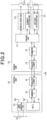
- the sensor unit 20 includes a current detection unit 21 that detects a current of the battery module 11, which is a detection target, and a voltage detection unit 22 that detects a voltage of the battery module 11, which is a detection target.
- a switch 23a is provided which is a switch unit that switches between energization and interruption of energization between the battery module 11, which is a detection target, and the electrical load 13.
- the sensor unit 20 includes a switch drive unit 23 that performs on/off-control of the switch 23a.
- the switch 23a is, for example, a relay switch.
- the switch 23a may be implemented by a pyro fuse.
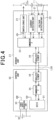
- the MCU 31 outputs a notification signal for making a notification that the control unit 30 and the communication path L38 are normal every time a certain time period T1 has elapsed.
- the certain time period T1 may be any time period, for example, 5 minutes.
- step S201 determines that an abnormality is caused in the communication path L38, the MCU 31, or the like (step S204). Then, the switch drive unit 23 maintains an on state of the switch 23a until a predetermined allowable time Ton elapses (step s205).
- the allowable time To is a time period (e.g. about five minutes) during which the own vehicle can be moved to the side of the road at which no obstruction to travel of other vehicles is caused, and is preferably as short as possible.
- the switch drive unit 23 changes the switch 23a to an off state to interrupt energization of the battery module 11 (step s206).
- the configuration of the control unit 30 according to the third embodiment will be described.
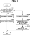
- the MCU 31 of the control unit 30 performs a switch drive instruction process illustrated in FIG. 7 at predetermined intervals.
- the MCU 31 determines whether the communication path L38 and the sensor unit 20 are normal (step S301). Specifically, the MCU 31 detects a disconnection of the communication path L38 (including an abnormality of elements provided to the communication path L38) and an abnormality of the sensor unit 20.
- the method of detecting a disconnection of the communication path L38 is similar to that of the first embodiment.
- An abnormality of the sensor unit 20 can be detected by various methods, for example, when there is no response from the sensor unit 20, or when an abnormality signal is received from the sensor unit 20. These abnormality determination methods may be well-known methods.
- the MCU 31 stops supplying drive electrical power to the sensor unit 20 (step S305). Hence, since the switch drive unit 23 cannot maintain the on state of the switch 23a, the switch 23a is changed to an off state. As a result, the energization between the battery module 11 and the electrical load 13 is interrupted.
- step S303 determines whether the battery module 11 and the electrical load 13 is interrupted. If the determination result of step S303 is affirmative, the MCU 31 proceeds to step S305 to stop supplying drive electrical power to the sensor unit 20. Hence, as described above, the energization between the battery module 11 and the electrical load 13 is interrupted.
- the configuration of the above first embodiment may be modified as the following fourth embodiment.
- the third embodiment part different from the configurations described in the above embodiments will be mainly described.
- the fourth embodiment as a basic configuration, the vehicular power supply system 100 of the first embodiment will be exemplified.
- the sensor unit 20 includes a plurality of (two in the present embodiment) current detection unit 21. It is noted that, unlike the first embodiment, the voltage detection unit 22 may be included or not be included.
- the two current detection units 21 detect currents at different positions.
- a first current detection unit 21a and a second current detection unit 21b are included.
- the first current detection unit 21a detects a current (first current value) at a first position P1 in the vicinity of the battery module 11 on the electrical path, which is a detection target, of the sensor unit 20.
- the second current detection unit 21b is farther from the battery module 11 than the first current detection unit 21a and detects a current (second current value) at a second position P2 in the vicinity of the switch 23a on the electrical path.
- the first current detection unit 21a detects a current at the first position P1. If the value of the current is a predetermined first threshold value or greater, the first current detection unit 21a outputs a first detection signal indicating this.
- the second current detection unit 21b detects a current at the second position P2. If the value of the current is a predetermined second threshold value or greater, the second current detection unit 21b outputs a second detection signal indicating this.
- the first threshold value and the second threshold value are set to the same value Th.
- the configuration of the above fourth embodiment may be modified as the following fifth embodiment.
- part different from the configurations described in the above embodiments will be mainly described.
- the vehicular power supply system 100 of the fourth embodiment will be exemplified.
- a discharge circuit 51 for quickly discharging charge of the capacitor C1 is provided between the battery module 11 and the electrical load 13.
- the discharge circuit 51 is connected with the capacitor C1, the battery module 11, and the electrical load 13 in parallel.
- the discharge circuit 51 is configured of a series connection of a resistor R10 and a switch 23b.
- the switch 23b is normally set so as to be an off state (energization interruption state).
- the sensor unit 20 of the fifth embodiment includes, as in the fourth embodiment, the first current detection unit 21a, the second current detection unit 21b, the AND circuit AND1, and the switch drive unit 231.
- the sensor units 20 of the fifth embodiment includes, in addition to the above configuration, a second switch drive unit 232. It is noted, in the fifth embodiment, the switch drive unit 231 is referred to as a first switch drive unit 231 as a matter of convenience.
- the second switch drive unit 232 is connected to an output terminal of the AND circuit AND1 via a delay circuit D1. As illustrated in FIG. 11 , if the first detection signal and the second detection signal are input to the AND circuit AND1, and the AND circuit AND1 outputs an overcurrent detection signal, the overcurrent detection signal is input to the second switch drive unit 232 by the delay circuit D1 later than to the switch drive unit 231 by predetermined time.
- the second switch drive unit 232 changes the switch 23b to an on state to cause the discharge circuit 51 to discharge charge of the capacitor C1.
- the charge of the capacitor C1 can be quickly discharged.
- the configuration of the above fifth embodiment may be modified as the following sixth embodiment.
- part different from the configurations described in the above embodiments will be mainly described.
- the vehicular power supply system 100 of the fifth embodiment will be exemplified.
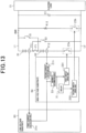
- the assembled battery 10 in the sixth embodiment is configured by a first battery module 61 and a second battery module 62.
- the first battery module 61 and the second battery module 62 are configured to be able to be changed between a serial connection and a parallel connection.
- the first connection changing switch S1 and the second connection changing switch S2 are changed to off states.
- the first connection changing switch S1 and the second connection changing switch S2 are changed to on states.
- the sensor unit 20 is provided with a low-voltage substrate 63 whose drive electrical power has a low voltage and a high-voltage substrate 64 whose drive electrical power is higher than that of the low-voltage substrate 63.
- the low-voltage substrate 63 is provided with the first current detection unit 21a.
- the high-voltage substrate 64 is provided with the second current detection unit 21b.
- the first current detection unit 21a detects a current flowing through a first point P11 located on the negative electrode terminal side of the first battery module 61 with respect to a connection point of the second connection changing switch S2 on the electrical path between the first battery module 61 and the second battery module 62.
- the first point P11 is a point at which a current from the first battery module 61 can be detected in any connection manner.
- the second current detection unit 21b detects a current flowing through a second point P12 located on the positive electrode terminal side of the second battery module 62 with respect to a connection point of the first connection changing switch S1 on the electrical path between the first battery module 61 and the second battery module 62.
- the second point P12 is a point at which a current from the second battery module 62 can be detected in any connection manner.
- the first current detection unit 21a and the second current detection unit 21b are connected to an abnormality determination circuit 53.
- the abnormality determination circuit 53 is provided to the high-voltage substrate 64.
- the abnormality determination circuit 53 is configured to receive connection information concerning whether the first battery module 61 and the second battery module 62 are connected in series.
- the abnormality determination circuit 53 If the first battery module 61 and the second battery module 62 are connected in series, when receiving the first detection signal and the second detection signal, the abnormality determination circuit 53 outputs an overcurrent detection signal. In contrast, if the first battery module 61 and the second battery module 62 are connected in parallel (not in series), when receiving any of the first detection signal and the second detection signal, the abnormality determination circuit 53 outputs an overcurrent detection signal.
- the sensor unit 20 of the sixth embodiment includes, as in the fifth embodiment, the first switch drive unit 231 and the second switch drive unit 232.
- the first switch drive unit 231 in the sixth embodiment is connected to the abnormality determination circuit 53 and is configured to be able to receive the overcurrent detection signal.
- the first switch drive unit 231 is configures to, on receiving the overcurrent detection signal from the abnormality determination circuit 53, change the switch 23a from an on state to an off state.
- the second switch drive unit 232 On receiving the overcurrent detection signal, the second switch drive unit 232 changes the switch 23b to an on state. Hence, the switch 23b becomes an on state after the predetermined time elapses from when the first switch drive unit 231 changes the switch 23b to an off state. Thus, charge of the capacitor C1 is discharged by the discharge circuit 51.
- the above sixth embodiment has, in addition to the effects of the above fifth embodiment, the following effects.
- the first battery module 61 and the second battery module 62 are connected in series.
- the first battery module 61 and the second battery module 62 are connected in parallel.
- the charging voltage can be lowered, while the electrical power supplied to the electrical load 13 becomes a high voltage.
- the configuration for increasing the charging voltage supplied from the rotary electric machine can be omitted or simplified.
- a vehicular power supply system (100) including a sensor unit (20) that detects a battery state of a storage battery (11) that is capable of supplying electrical power to an electrical load (13), and a control unit (30) that receives the battery state from the sensor unit via a communication path (L38) and performs instruction to perform energization and interruption of the energization between the storage battery and the electrical load based on the received battery state, wherein the sensor unit includes:
Landscapes
- Engineering & Computer Science (AREA)
- Power Engineering (AREA)
- Mechanical Engineering (AREA)
- Life Sciences & Earth Sciences (AREA)
- Sustainable Development (AREA)
- Sustainable Energy (AREA)
- Transportation (AREA)
- Charge And Discharge Circuits For Batteries Or The Like (AREA)
- Secondary Cells (AREA)
- Protection Of Static Devices (AREA)
Applications Claiming Priority (2)
| Application Number | Priority Date | Filing Date | Title |
|---|---|---|---|
| JP2021136438A JP7416027B2 (ja) | 2021-08-24 | 2021-08-24 | 車両用電源システム |
| PCT/JP2022/030778 WO2023026874A1 (fr) | 2021-08-24 | 2022-08-12 | Système d'alimentation électrique pour véhicule |
Publications (2)
| Publication Number | Publication Date |
|---|---|
| EP4393777A1 true EP4393777A1 (fr) | 2024-07-03 |
| EP4393777A4 EP4393777A4 (fr) | 2025-02-19 |
Family
ID=85323217
Family Applications (1)
| Application Number | Title | Priority Date | Filing Date |
|---|---|---|---|
| EP22861163.8A Pending EP4393777A4 (fr) | 2021-08-24 | 2022-08-12 | Système d'alimentation électrique pour véhicule |
Country Status (5)
| Country | Link |
|---|---|
| US (1) | US12391121B2 (fr) |
| EP (1) | EP4393777A4 (fr) |
| JP (1) | JP7416027B2 (fr) |
| CN (1) | CN117858822A (fr) |
| WO (1) | WO2023026874A1 (fr) |
Families Citing this family (3)
| Publication number | Priority date | Publication date | Assignee | Title |
|---|---|---|---|---|
| US12246665B2 (en) | 2023-05-22 | 2025-03-11 | Joseph & Roberts, LLC | System and method for powering a vehicle accessory |
| DE102024118959A1 (de) * | 2024-07-04 | 2026-01-08 | Bayerische Motoren Werke Aktiengesellschaft | Hochvoltsystem mit aktiver Entladung von X-Kapazitäten |
| EP4714714A1 (fr) * | 2024-09-19 | 2026-03-25 | Volvo Truck Corporation | Procédé de commande d'un système d'énergie dans un véhicule |
Family Cites Families (14)
| Publication number | Priority date | Publication date | Assignee | Title |
|---|---|---|---|---|
| JP2008195255A (ja) * | 2007-02-14 | 2008-08-28 | Toyota Motor Corp | 車両の電源システム |
| JP2008312396A (ja) * | 2007-06-15 | 2008-12-25 | Yazaki Corp | 車両用電源システム |
| JP2012093343A (ja) * | 2010-09-30 | 2012-05-17 | Gs Yuasa Corp | 故障検出装置、故障検出方法 |
| JP5673658B2 (ja) * | 2012-12-03 | 2015-02-18 | トヨタ自動車株式会社 | 蓄電システム |
| US9889880B2 (en) * | 2014-03-11 | 2018-02-13 | Nsk Ltd. | Motor control device, electric power steering device using same, and vehicle |
| WO2015156371A1 (fr) * | 2014-04-10 | 2015-10-15 | 株式会社デンソー | Dispositif de commande, et dispositif d'allumage |
| JP6603085B2 (ja) * | 2015-09-04 | 2019-11-06 | 株式会社エンビジョンAescジャパン | 車両用電源装置及び車両制御装置 |
| JP6704895B2 (ja) | 2017-12-20 | 2020-06-03 | 株式会社Subaru | 電動車両の電源システム |
| JP7041567B2 (ja) * | 2018-03-27 | 2022-03-24 | 株式会社Subaru | 車両用電源装置 |
| JP7129008B2 (ja) * | 2018-11-29 | 2022-09-01 | トヨタ自動車株式会社 | 電源システム |
| JP7103199B2 (ja) * | 2018-12-17 | 2022-07-20 | 株式会社デンソー | プリチャージ制御装置 |
| JP7251222B2 (ja) * | 2019-03-11 | 2023-04-04 | 株式会社デンソー | 電動機制御装置および電動機制御方法 |
| JP7055777B2 (ja) | 2019-07-12 | 2022-04-18 | 矢崎総業株式会社 | 検出装置 |
| JP7543119B2 (ja) | 2020-02-25 | 2024-09-02 | 芝浦メカトロニクス株式会社 | 基板処理装置 |
-
2021
- 2021-08-24 JP JP2021136438A patent/JP7416027B2/ja active Active
-
2022
- 2022-08-12 WO PCT/JP2022/030778 patent/WO2023026874A1/fr not_active Ceased
- 2022-08-12 EP EP22861163.8A patent/EP4393777A4/fr active Pending
- 2022-08-12 CN CN202280057832.XA patent/CN117858822A/zh active Pending
-
2024
- 2024-02-26 US US18/586,737 patent/US12391121B2/en active Active
Also Published As
| Publication number | Publication date |
|---|---|
| JP2023030995A (ja) | 2023-03-08 |
| US20240190252A1 (en) | 2024-06-13 |
| WO2023026874A1 (fr) | 2023-03-02 |
| EP4393777A4 (fr) | 2025-02-19 |
| CN117858822A (zh) | 2024-04-09 |
| US12391121B2 (en) | 2025-08-19 |
| JP7416027B2 (ja) | 2024-01-17 |
Similar Documents
| Publication | Publication Date | Title |
|---|---|---|
| KR102329913B1 (ko) | 배터리의 작동을 모니터링하고 조절하기 위한 배터리 관리 시스템 및 이러한 배터리 관리 시스템을 구비한 배터리 시스템 | |
| KR101234059B1 (ko) | 셀 밸런싱부의 고장 진단 장치 및 방법 | |
| US12391121B2 (en) | Vehicular power supply system | |
| EP2879900B1 (fr) | Système de stockage électrique | |
| US10090683B2 (en) | Battery management system for controlling an energy storage assembly and method for charging and discharging an energy storage assembly | |
| EP2485364B1 (fr) | Dispositif de commande de batterie assemblé | |
| US9941712B2 (en) | Electrical storage system | |
| CN105612082B (zh) | 电压控制地自动切断电子部件或者电池组电池的方法和设备 | |
| US10096992B2 (en) | Electrical storage system | |
| US9840157B2 (en) | Battery management system and battery system | |
| US11418042B2 (en) | Battery management unit | |
| JP2013092397A (ja) | 電池監視装置 | |
| EP3349327B1 (fr) | Dispositif de gestion de batterie | |
| CN103998946A (zh) | 监视系统和车辆 | |
| KR20180115239A (ko) | 안전 모니터링 유닛 | |
| CN106688156B (zh) | 车辆用蓄电池系统 | |
| US20250330030A1 (en) | Electricity storage apparatus and method of interrupting electric current | |
| EP4068547A1 (fr) | Système de batterie monté sur véhicule | |
| EP4495611A1 (fr) | Dispositif de source d'alimentation | |
| CN115241954A (zh) | 一种车用智能配电管理系统及方法 | |
| US20210273469A1 (en) | Method for operating a battery module | |
| JP2020022366A (ja) | 車両 | |
| US20250192255A1 (en) | Battery system | |
| EP4678480A1 (fr) | Dispositif de distribution d'énergie et procédé de détermination de déconnexion de fil | |
| JP7613946B2 (ja) | 電源システム |
Legal Events
| Date | Code | Title | Description |
|---|---|---|---|
| STAA | Information on the status of an ep patent application or granted ep patent |
Free format text: STATUS: THE INTERNATIONAL PUBLICATION HAS BEEN MADE |
|
| PUAI | Public reference made under article 153(3) epc to a published international application that has entered the european phase |
Free format text: ORIGINAL CODE: 0009012 |
|
| STAA | Information on the status of an ep patent application or granted ep patent |
Free format text: STATUS: REQUEST FOR EXAMINATION WAS MADE |
|
| 17P | Request for examination filed |
Effective date: 20240307 |
|
| AK | Designated contracting states |
Kind code of ref document: A1 Designated state(s): AL AT BE BG CH CY CZ DE DK EE ES FI FR GB GR HR HU IE IS IT LI LT LU LV MC MK MT NL NO PL PT RO RS SE SI SK SM TR |
|
| DAV | Request for validation of the european patent (deleted) | ||
| DAX | Request for extension of the european patent (deleted) | ||
| REG | Reference to a national code |
Ref country code: DE Ref legal event code: R079 Free format text: PREVIOUS MAIN CLASS: B60R0016020000 Ipc: B60L0003000000 |
|
| STAA | Information on the status of an ep patent application or granted ep patent |
Free format text: STATUS: EXAMINATION IS IN PROGRESS |
|
| A4 | Supplementary search report drawn up and despatched |
Effective date: 20250116 |
|
| RIC1 | Information provided on ipc code assigned before grant |
Ipc: H02J 7/00 20060101ALI20250110BHEP Ipc: H02H 7/20 20060101ALI20250110BHEP Ipc: H02H 7/18 20060101ALI20250110BHEP Ipc: B60R 16/02 20060101ALI20250110BHEP Ipc: B60L 58/12 20190101ALI20250110BHEP Ipc: B60L 3/04 20060101ALI20250110BHEP Ipc: B60L 3/00 20190101AFI20250110BHEP |
|
| 17Q | First examination report despatched |
Effective date: 20250217 |