EP4393788B1 - Kupplung für schienenfahrzeug - Google Patents
Kupplung für schienenfahrzeug Download PDFInfo
- Publication number
- EP4393788B1 EP4393788B1 EP22216703.3A EP22216703A EP4393788B1 EP 4393788 B1 EP4393788 B1 EP 4393788B1 EP 22216703 A EP22216703 A EP 22216703A EP 4393788 B1 EP4393788 B1 EP 4393788B1
- Authority
- EP
- European Patent Office
- Prior art keywords
- coupler head
- coupling
- coupler
- operational position
- pivoting mechanism
- Prior art date
- Legal status (The legal status is an assumption and is not a legal conclusion. Google has not performed a legal analysis and makes no representation as to the accuracy of the status listed.)
- Active
Links
Images


Classifications
-
- B—PERFORMING OPERATIONS; TRANSPORTING
- B61—RAILWAYS
- B61G—COUPLINGS; DRAUGHT AND BUFFING APPLIANCES
- B61G7/00—Details or accessories
- B61G7/08—Adjustable coupling heads
-
- B—PERFORMING OPERATIONS; TRANSPORTING
- B61—RAILWAYS
- B61G—COUPLINGS; DRAUGHT AND BUFFING APPLIANCES
- B61G5/00—Couplings for special purposes not otherwise provided for
- B61G5/04—Couplings for special purposes not otherwise provided for for matching couplings of different types, i.e. transitional couplings
Definitions
- This invention relates to a coupling for a rail vehicle, in particular in relation to automatic coupling systems (AC) in rail freight transportation (RFT), more specifically in relation to digital automatic coupling systems (DAC), and most specifically in relation to coupling systems which can be used alternatively as a screw coupling (SC) and as an automatic coupling (AC or DAC).
- AC automatic coupling systems
- RFT rail freight transportation
- DAC digital automatic coupling systems
- SC screw coupling
- AC or DAC automatic coupling
- An SC coupling is a coupling which comprises a shackle which is suitable to be manually coupled to a draw hook, typically according to the standard EN 15566:2016.
- an AC coupling offers automatic coupling of the mechanical connection of two coupler heads (AC Type 1 to Type 3).
- the coupler head of an AC coupling has the characteristics as defined in section 4.1 of the standard SS-EN 16019:2014.
- a DAC coupling is an AC coupling which further offers automatic connection of power and data lines so that electric energy and digital information can be transmitted between two couplings that are coupled together (DAC Type 4 and Type 5).
- EP 3590784 A1 discloses an automatic coupler head which is attached to a rail vehicle by means of a coupler shank, wherein the coupler head is pivotably connected to the free end of the coupler shank so that it can rotate about a horizontal axis between a horizontal, operational position and a vertical, non-operational position.
- the coupler head is held in the vertical, non-operational position by means of a wire which can be tightened and loosened by means of a drive. Upon loosening the wire, the coupler head may rotate into its operational position due to its weight.
- a shackle of a screw coupling When the coupler head is rotated about the horizontal axis to its vertical, non-operational position, a shackle of a screw coupling automatically rotates about the same horizontal axis from a lower, non-operational position into an upper, horizontal, operational position. Axial forces acting on the automatic coupler head and the shackle of the screw coupling are transmitted into the coupler shank via a horizontal bolt about which both the automatic coupler head and the shackle of the screw coupling are pivotably mounted.
- EP 3992054 A1 discloses a foldable coupler including a coupler head, a rotating arm mechanism with a first arm connected to a vehicle body and a second arm, which is rotatably/foldably attached to the first arm, connected to the coupler head.
- a pneumatic cylinder is mounted on the second arm and a force transfer rod is rotatably mounted on the first arm, wherein the pneumatic cylinder is connected to the force transfer rod so as to transfer a driving force to the first arm through the force transfer rod so that the first arm and the second arm rotate relative to each other.
- the second arm further includes a locking groove, including a bilateral wall
- the foldable coupler further includes a locking block, which is rotatably connected with the first arm, the rotation center of which is located above or below the locking groove, and which is able to be clamped into and disengaged from the locking groove during the rotation process.
- a pull rope is connected with the force transfer rod and the locking block, respectively, in order to transfer the driving force from the force transfer rod to the locking block so that during the rotation of the force transfer rod, the locking block is driven to disengage from the locking groove before the first arm and the second arm can rotate relative to each other when the coupler is being folded.
- a spring urges the locking block back into the locking groove.
- WO 2008/132124 A1 discloses a foldable coupler with a pivoting mechanism for pivoting the a front part of a shaft, the pivoting mechanism comprising a locking bar being guided in a cam disk guide, on the one hand, and in a guide rail, on the other hand.
- US 653075 A discloses a foldable coupler in which the coupler head is supported in its operational position using a knee lever arrangement.
- a piston working in an air cylinder is used to bring the knee lever into its extended position so as to securely hold the coupler head in the operational position.
- one aspect of the present disclosure relates to a coupling for a rail vehicle, preferably a freight locomotive, which comprises a coupler shank for attaching the coupling to a rail vehicle and a coupler head pivotably connected to a free end of the coupler shank so as to rotate about a primary axis, preferably a horizontal axis, between an operational position and a non-operational position.
- the coupling further comprises a locking member configured to assume a locking position in which it blocks rotation of the coupler head about the primary axis when the coupler head is in the operational position as well as a pivoting mechanism configured to rotate the coupler head about the primary axis, wherein the pivoting mechanism is configured to release the locking member.
- the coupler head is securely held in its horizontal, operational position by means of the locking member.
- the locking member since the locking member is configured to block rotation of the coupler head in the coupler head's operational position, it may transmit forces from the coupler head to the coupler shank which would otherwise cause a rotation of the coupler head out of its operational position.
- the pivoting mechanism which is arranged to move the coupler head between its operational and non-operational positions, assumes the additional function of releasing the locking member, thereby allowing the coupler head's movement from the operational toward the non-operational position. This way, a train driver can simply actuate the pivoting mechanism from inside the locomotive's cabin in order to bring the coupler head out of the way.
- the pivoting mechanism is configured to rotate the coupler head about the primary axis from the coupler head's non-operational position toward the coupler head's operational position, particularly downward. This way, by means of the pivoting mechanism, movement of the coupler head from its non-operational position toward the operational position is even possible where the coupler head may be stuck in its non-operational position, e.g. vertical position, such as in icy weather conditions.
- the pivoting mechanism is configured such that when it is actuated so as to rotate the coupler head from the coupler head's operational position to the coupler head's non-operational position, the pivoting mechanism moves from an operational state to an interim state in a first period and from the interim state to a non-operational state in a second period, thereby releasing the locking member during the first period and rotating the coupler head into the non-operational position during the second period.
- These two steps, releasing the locking member and rotating the coupler head are preferably interconnected so as to achieve a continuous movement, i.e. such that the second period starts immediately when the first period ends. More preferably, these two steps are caused by movement of the pivoting mechanism in one direction, e.g. by moving a driving element of the pivoting mechanism in one direction.
- the arrangement is such that both functions of the coupling, the rotation and the blocking of the coupler head, are caused by one and the same pivoting mechanism, which facilitates the handling of the coupling substantially.
- This is particularly the case where the pivoting mechanism is automatically driven so that the train driver can trigger such actions remotely from the locomotive cabin.
- the arrangement is preferably such that, when the coupling is attached to a rail vehicle with the primary axis inclined or horizontal, the pivoting mechanism lifts the coupler head upward when the pivoting mechanism rotates the coupler head from the coupler head's operational position toward the coupler head's non-operational position.
- the weight of the coupler head helps lowering the coupler head when it is moved in the opposite direction, i.e. from the non-operational position to the operational position.
- the coupler head is substantially out of the way because the space above the coupler head is typically free and not of a particular use.
- the pivoting mechanism comprises a rod having a first end section connected to the coupler shank and a second end section connected to the coupler head, wherein at least one of the first and second end sections is pivotably mounted and wherein the rod pivots about the at least one pivotably mounted end section when the pivoting mechanism moves from the operational state to the interim state and further from the interim state to the non-operational state. Due to the rod being connected to both the coupler shank and the coupler head and being pivotable, rotation of the rod about the pivot point causes a relative movement between the coupler shank and the coupler head, more specifically a rotation of the coupler head about the primary axis.
- the pivoting mechanism may comprise an oblong hole.
- the oblong hole which enables the second end section of the rod, when the pivoting mechanism moves from the operational state to the interim state during the first period, to move relative to the coupler head without causing rotation of the coupler head, and further, when the pivoting mechanism moves from the interim state to the non-operational state during the second period, to cause rotation of the coupler head.
- the rod is connected to the locking member in such a manner that the locking member is released when the pivoting mechanism moves from the operational state to the interim state in the first period.
- a single, preferably continuous, movement of the rod causes both release of the locking member and subsequent rotation of the coupler head.
- the pivoting mechanism comprises a cylinder and a plunger extending from the cylinder, wherein the arrangement is such that the cylinder and the plunger move relative to one another along a common longitudinal axis when the pivoting mechanism moves from the operational state to the interim state and further from the interim state to the non-operational state.
- the cylinder and plunger form the actual drive of the pivoting mechanism with the afore-mentioned rod being a drive member of the pivoting mechanism which is driven by the plunger and cylinder.
- the cylinder is a hydraulic cylinder so that hydraulic fluid can be used for driving the pivoting mechanism, a hydraulic system being commonly available on trains.
- the cylinder is a double-acting cylinder so as to enable the pivoting mechanism to urge the coupler head toward both the coupler head's non-operational position, e.g. toward its vertical position, when it is in the operational position, and the coupler head's operational position when it is in the (vertical) non-operational position.
- the cylinder or the plunger may be attached to the rod so as to pivot the rod about its pivotably attached end section when the pivoting mechanism moves from the operational state to the interim state and further from the interim state to the non-operational state.
- the cylinder and plunger form part of the rod itself such that the rod is extendable.
- the design according to the present invention is such that a first force which needs to be overcome by the pivoting mechanism in order to release the locking member and which acts on the first end section of the rod is lower than a second force which needs to be overcome by the pivoting mechanism in order to rotate the coupler head from its operational position toward its non-operational position and which acts on the second end section of the rod.
- a first force which needs to be overcome by the pivoting mechanism in order to release the locking member and which acts on the first end section of the rod is lower than a second force which needs to be overcome by the pivoting mechanism in order to rotate the coupler head from its operational position toward its non-operational position and which acts on the second end section of the rod.
- the coupler head is rotated from its operating position toward its non-operating position only after the locking member has already been released.
- both the first end section and the second end section of the rod are pivotably mounted, which means that these pivot mountings can transmit only axial forces and no torsional forces, whereas - according to the invention - the first and second forces that need to be overcome by the cylinder-plunger-arrangement are axial forces which act on the rod in opposite directions along a longitudinal axis of the rod.
- the second (higher) force that needs to be overcome and acts on the second end section of the rod attached to the coupler head may partially or completely result from the weight of the coupler head.
- such force may also be provided solely or in addition by a spring, which is specifically needed in cases where the primary axis about which the coupler head is rotated is a vertical axis.
- the first end section of the rod is pivotably mounted to a swivel member.
- the swivel member is, on the one hand, pivotably mounted to the coupler shank either directly or indirectly and, on the other hand, connected to or integrally forming the locking member such that, when the pivoting mechanism moves from the operational state toward the interim state, the swivel member swivels and, thereby, releases the locking member.
- a stop may be provided and arranged such that rotation of the coupler head from the coupler head's operational position toward the coupler head's non-operational position begins after the swivel member has reached the stop.
- the invention can preferably be used on a digital automatic coupling (DAC).
- DAC couplings are provided with an electric coupler for electrically connecting the coupling to an electric coupler of another coupling.
- an electric coupler for electrically connecting the coupling to an electric coupler of another coupling.
- the locking member when the coupler head is in its operational position, is arranged in a gap between the coupler head and the coupler shank so as to transmit axial forces between the coupler head and the coupler shank.
- this is preferably provided in the form of a wedge having opposing sides which engage with opposing walls of the gap into which the wedge is inserted when the coupler head is in its operational position. Forces acting on the coupler head are thus transferred through the locking member to the coupler shank.
- the wedge or the gap or both the wedge and the gap are tapered.
- the wedge can be urged into the gap by means of the pivoting mechanism so as to avoid a space between the cooperating walls but rather obtain a tight fit between the wedge and the walls of the gap.
- a totality of the tapers between the sides of the wedge and the walls of the gap may be between 1° and 5°.
- one side of the wedge may be tapered by +0.5° whereas the cooperating wall of the gap is not tapered and the other side of the wedge may be tapered by -0.5° whereas the cooperating wall of the gap is again not tapered, in which case the totality of tapers is 1°. This allows movement of the wedge into the gap until the walls of the wedge are pressing against the associated walls of the gap.
- the movement of the locking member - or wedge - is perpendicular to a longitudinal axis of the coupler shank, more preferably substantially vertically.
- the coupler head is a DAC or AC coupler head and the coupling further comprises an SC coupler head which is operable when the DAC or AC coupler head is in its non-operational position.
- a corresponding method is likewise disclosed, i.e. a method of bringing a coupler head of a coupling of a rail vehicle from an operational position into a non-operational position, namely the coupling described above, comprising the steps of releasing the locking member during a first period and rotating the coupler head into the non-operational position during a second period. These steps are, as stated, interconnected such that the second period starts when the first period ends.
- Fig. 1 is a perspective view of a coupling according to a first embodiment of the present disclosure.
- the coupling comprises a coupler head 1 of the Scharfenberg-type, more specifically a Scharfenberg-type 10 coupling.
- the coupler head 1 is connected to a coupler shank 2 by which the coupling can be attached to the body of a rail vehicle, preferably a freight locomotive (not shown).
- a rail vehicle preferably a freight locomotive (not shown).
- Figs. 2 and 3 are side views of the front part of the coupling showing the coupler head 1 in its operational, preferably horizontal, position (shown in Fig. 2 ) and in its non-operational, preferably vertically lifted, position (shown in Fig. 3 ).
- a rod 3 comprising a cylinder 4 and plunger 5 extending from the cylinder 4 is attached with a first end area 3A thereof to the coupler shank 2 and with a second end area 3B thereof to the coupler head 1. More specifically, the second end 3B of the rod is attached to an attachment point at a rear part of the coupler head 1 which leaves room for an electric coupler 100 to be arranged on the coupler head 1 in front of such attachment point.
- the electric coupler 100 is designed for electrically connecting the coupling to an electric coupler of another coupling in order to transfer energy as well as data.
- the second end region 3B of the rod 3 is pivotably connected to the coupler head 1 and the second end region 3A of the rod 3 is pivotably connected to a swivel member 7 so that it can pivot about a pivot axis 3C.
- the swivel member 7 in turn, is mounted on the coupler shank 2 so that it can swivel about a swivel axis 7A.
- the swivel axis 7A of the swivel member 7 and the pivot axis 3C of the rod 3 are in parallel to each other.
- the pivot axis 3C of the rod 3 is not easily recognizable from Fig. 4 or Fig.
- FIG. 5A and can be better derived from Fig. 5B , which shows the same side view as Fig. 5A , however, at a different cross-sectional plane which cuts through the rod 3 and the pivotable attachment of the rod 3 to the swivel member 7.
- the swivel element 7 comprises a locking member 8 which is rotatably mounted to the swivel member 7 but which may alternatively form an integral part thereof.
- the functioning of the overall pivoting mechanism, by which the coupler head 1 is rotated about the primary axis 6, is as follows.
- Fig. 5A shows the coupler head 1 in its operational, preferably horizontal position. Then the length of the rod 3 is reduced using hydraulic or pneumatic pressure inside the cylinder-plunger-arrangement in order to lift the coupler head 1 upward.
- the swivel member 7 will first swivel about the swivel axis 7A until it abuts against a stop 9 (shown in the cross-sectional view of Fig. 5B ). Only thereafter will the coupler head 1 start to be raised. This is due to the fact that the forces acting on the first end 3A of the rod 3 are substantially only frictional forces which are substantially lower than the forces acting on the rod's other end section 3B caused by the weight of the coupler head 1 and/or spring force.
- the pivoting mechanism reaches an interim state which is shown in Fig. 6 and in which state the swivel member 7 abuts against the stop 9.
- this first period i.e. the period in which the pivoting mechanism moves from the operational state (5A/5B) to the interim state ( Fig. 6 )
- the locking member 8 connected to the swivel member 7 is lifted and, thereby, released.
- the movement of the locking member 8 is perpendicular to a longitudinal axis of the coupler shank, namely substantially vertically. More specifically, in the operational state of the pivoting mechanism, the locking member 8 is inserted in a gap 10 and blocks the rotation of the coupler head 1 about the primary axis 6. Once it has been lifted from the gap 10, as shown in Fig. 6 , the blocking is released so as to allow the coupler head 1 to rotate about the primary axis 6.
- Such rotation of the coupler head 1 from its operational, but released position as shown in Fig. 6 to its non-operational position as shown in Fig. 7 occurs during a second period which starts after the first period has ended.
- further reduction of the length of the rod 3 by means of the cylinder-plunger-arrangement causes the rotation of the coupler head 1, in particular lifting thereof if the primary axis 6 is non-vertical.
- the cylinder is a double-acting cylinder, meaning that it is not only able to rotate the coupler head 1 about the primary axis 6 in one direction but also in the opposite direction. This is advantageous in order to lower the coupler head 1 from its vertical position in particular in situations where rotation about the primary axis is blocked, e.g. caused by icy weather conditions.
- the double-acting cylinder is relevant in this particular embodiment in order to urge the locking member 8 back into the gap 10 once the coupler head 1 has reached its operational, but unlocked position, i.e. the position shown in Fig. 6 .
- a lower rear end 1A of the coupler head 1 abuts against a lower front end 2A of the coupler shank 2. This is substantially caused by the weight of the coupler head 1 (and/or by a spring force, in particular when the primary axis 6 is not horizontal but vertical). Due to this abutment, axial forces are securely transferred from the coupler head 1 into the coupler shank 2.
- any forces which do not strictly act axially on the coupler head 1 may cause rotation of the coupler head 1 about the primary axis 6.
- the locking member 8 in the gap 10 prevents such rotation and, furthermore, transfers part of the forces from the coupler head 1 to the coupler shank 2, thereby providing a more equal distribution of transmitted forces from the coupler head 1 to the coupler shank 2.
- the locking member 8 of this embodiment is wedge-shaped and tapered and/or the gap 10 is tapered so that at a certain point of insertion of the locking member 8 in the gap 10 the opposing sides of the locking member will come into contact with opposing walls of the gap. This ensures that there is no slack in the connection between the coupler head 1 and the coupler shank 2.
- the totality of tapers of the sides of the wedge and the walls of the gap is between 1° and 5°, i.e. in a symmetrical arrangement of the locking member 8 inside the gap 10 there may be a residual angular gap on each side of the locking member 8 of between 0.5° and 2.5°.
- the front end of the locking member 8 may be chamfered in order to facilitate the initial moment of insertion of the locking member 8 into the gap 10.
- FIGs. 5A to 7 show the coupling with a screw coupler (SC) hanging down from the primary axis 6.
- a shackle is pivotably connected to the front end of the screw coupling SC.
- the shackle 20 is hooked into a transportation hook 21 mounted underneath the coupler head 1 so as to hold the screw coupling SC when the automatic coupler head 1 is operational.
- the shackle 20 can be unhooked from the transportation hook 21 and later hooked onto a draw hook of a corresponding screw coupling of another rail vehicle.
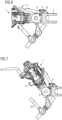
- Figs. 8 to 9 show a second embodiment according to the present disclosure in which the cylinder-plunger-arrangement does not form part of the rod 3 but is pivotably attached with one end to the rod 3 and with an opposing end to the coupler shank 2.
- the locking member 8 forms part of the rod 3 but may equally be connected to the rod 3 in a pivotable manner, similar to the arrangement discussed above in relation to the first embodiment.
- the locking member 8 is inserted in the gap 10 between the coupler head 1 and coupler shank 2, thereby blocking rotation of the coupler head 1 about the primary axis 6.
- forces are transmitted from the coupler head 1 to the coupler shank 2 via the lower and upper rear ends of the coupler head 1 in this position of the coupler head, in the same way as described above in relation to the first embodiment.
- the rod 3 rotates about a pivot axis 3C at its rear end section 3A from an operational state as shown in Fig. 8 , through an interim state (not shown) in a first period, and from the interim state to the non-operational state as shown in Fig. 9 in a second period.
- the rod 3 is respectively moved in a single direction, which is a rotational direction about the pivot axis 3C.
- such movement is continuous.
- the second end section 3B at the front of the rod 3 is guided in an oblong hole 11 of the coupler head 1 so that the locking member 8 is released from the gap 10 without the coupler head 1 being rotated about the primary axis 6.
- the interim state of the pivoting mechanism is reached when the second end section 3B of the rod 3 reaches the opposite end of the oblong hole 11.
- the second period starts in which the coupler head 1 is rotated, preferably lifted, from its operational position shown in Fig. 8 to its non-operational position shown in Fig. 9 .
- the cylinder-plunger-arrangement preferably comprises a double-acting cylinder 4 by which the locking member 8 can be urged into the gap 10 when the coupler head 1 is rotated from its non-operational position back into its operational position.
Landscapes
- Engineering & Computer Science (AREA)
- Mechanical Engineering (AREA)
- Fittings On The Vehicle Exterior For Carrying Loads, And Devices For Holding Or Mounting Articles (AREA)
- Train Traffic Observation, Control, And Security (AREA)
Claims (15)
- Kupplung für ein Schienenfahrzeug, vorzugsweise eine Güterlokomotive, umfassend- einen Kupplungshals (2) zum Befestigen der Kupplung an einem Schienenfahrzeug,- einen Kupplungskopf (1), der schwenkbar mit einem freien Ende des Kupplungshals verbunden ist, so dass er sich um eine Hauptachse (6) zwischen einer Betriebsposition und einer Nichtbetriebsposition drehen kann,- ein Verriegelungselement (8), das so konfiguriert ist, dass es eine Verriegelungsposition einnimmt, in der es die Drehung des Kupplungskopfes (1) um die Hauptachse (6) blockiert, wenn sich der Kupplungskopf (1) in der Betriebsposition befindet, und- einen Schwenkmechanismus, der konfiguriert ist, um den Kupplungskopf (1) um die Hauptachse (6) zu drehen, wobei der Schwenkmechanismus konfiguriert ist, um das Verriegelungselement freizugeben,wobei sich der Schwenkmechanismus, wenn er betätigt wird, um den Kupplungskopf (1) aus der Betriebsposition des Kupplungskopfes in die Nichtbetriebsposition des Kupplungskopfes zu drehen, in einer ersten Periode von einem Betriebszustand in einen Zwischenzustand und in einer zweiten Periode von dem Zwischenzustand in einen Nichtbetriebszustand bewegt, wobei der Schwenkmechanismus so konfiguriert ist, dass er während der ersten Periode das Verriegelungselement (8) freigibt und während der zweiten Periode den Kupplungskopf (1) in die Nichtbetriebsposition dreht,wobei der Schwenkmechanismus einen Stab (3) mit einem ersten Endabschnitt (3A), der mit dem Kupplungshals (2) verbunden ist, und einem zweiten Endabschnitt (3B), der mit dem Kupplungskopf (1) verbunden ist, umfasst, wobei mindestens einer der ersten und zweiten Endabschnitte (3A, 3B) schwenkbar gelagert ist und wobei der Stab (3) um den mindestens einen schwenkbar gelagerten Endabschnitt (3A, 3B) schwenkt, wenn sich der Schwenkmechanismus vom Betriebszustand in den Zwischenzustand und weiter vom Zwischenzustand in den Nichtbetriebszustand bewegt,wobei der Schwenkmechanismus einen Zylinder (4) und einen sich von dem Zylinder (4) erstreckenden Stößel (5) umfasst, wobei die Anordnung derart ist, dass sich der Zylinder (4) und der Stößel (5) relativ zueinander entlang einer gemeinsamen Längsachse bewegen, wenn sich der Schwenkmechanismus von dem Betriebszustand in den Zwischenzustand und weiter von dem Zwischenzustand in den Nichtbetriebszustand bewegt, wobei der Zylinder (4) und der Stößel (5) einen Teil des Stabes (3) bilden, so dass der Stab (3) ausfahrbar ist,dadurch gekennzeichnet, dass eine erste Kraft, die durch den Schwenkmechanismus überwunden werden muss, um das Verriegelungselement (8) freizugeben, und die auf den ersten Endabschnitt (3A) des Stabs (3) wirkt, geringer ist als eine zweite Kraft, die durch den Schwenkmechanismus überwunden werden muss, um den Kupplungskopf (1) aus seiner Betriebsposition in seine Nichtbetriebsposition zu drehen, und die auf den zweiten Endabschnitt (3B) des Stabs (3) wirkt, wobei die erste Kraft und die zweite Kraft Kräfte sind, die auf den Stab (3) in entgegengesetzter Richtung entlang einer Längsachse des Stabs (3) wirken.
- Kupplung nach Anspruch 1, wobei der Schwenkmechanismus so konfiguriert ist, dass er den Kupplungskopf (1) um die Hauptachse (6) aus der Nichtbetriebsposition des Kupplungskopfes in Richtung der Betriebsposition des Kupplungskopfes dreht.
- Kupplung nach Anspruch 1 oder 2, wobei die Kupplung so konfiguriert ist, dass die Bewegung des Schwenkmechanismus vom Betriebszustand über den Zwischenzustand in den Nichtbetriebszustand eine Bewegung in eine Richtung ist, wobei die Kupplung vorzugsweise so konfiguriert ist, dass die Bewegung des Schwenkmechanismus vom Betriebszustand über den Zwischenzustand in den Nichtbetriebszustand eine kontinuierliche Bewegung ist.
- Kupplung nach einem der Ansprüche 1 bis 3, wobei der Zylinder (4) ein doppelt wirkender Zylinder ist, so dass der Schwenkmechanismus den Kupplungskopf (1) sowohl in die Nichtbetriebsposition des Kupplungskopfes als auch in die Betriebsposition des Kupplungskopfes drücken kann, wobei der Zylinder (4) vorzugsweise ein Hydraulikzylinder ist.
- Kupplung nach einem der Ansprüche 1 bis 4, wobei die zweite Kraft zumindest teilweise durch eine Feder veranlasst ist.
- Kupplung nach einem der Ansprüche 1 bis 5, wobei die zweite Kraft zumindest teilweise durch ein Gewicht des Kupplungskopfes (1) veranlasst ist.
- Kupplung nach einem der Ansprüche 1 bis 6, wobei der erste Endabschnitt (3A) des Stabes (3) schwenkbar an einem Schwenkelement (7) gelagert ist, das einerseits schwenkbar am Kupplungshals (2) gelagert ist und andererseits mit dem Verriegelungselement (8) verbunden ist oder dieses einstückig bildet, so dass bei einer Bewegung des Schwenkmechanismus aus dem Betriebszustand in den Zwischenzustand das Schwenkelement (7) schwenkt und dadurch das Verriegelungselement (8) freigibt, wobei die Konfiguration vorzugsweise so ist, dass die Drehung des Kupplungskopfes (1) aus der Betriebsposition des Kupplungskopfes in Richtung der Nichtbetriebsposition des Kupplungskopfes beginnt, nachdem das Schwenkelement (7) einen Anschlag (9) erreicht hat.
- Kupplung nach einem der Ansprüche 1 bis 7, wobei die Kupplung eine digitale automatische Kupplung ist, wobei der zweite Endabschnitt (3B) des Stabs (3) an einem Befestigungspunkt an einem hinteren Teil des Kupplungskopfs (1) befestigt ist und wobei ein elektrischer Kuppler (100) zum elektrischen Verbinden der Kupplung mit einem elektrischen Kuppler einer anderen Kupplung vor dem Befestigungspunkt am Kupplungskopf (1) angeordnet ist.
- Kupplung nach einem der Ansprüche 1 bis 8, wobei das Verriegelungselement (8), wenn der Kupplungskopf (1) in seiner Betriebsposition ist, in einer Lücke (11) angeordnet ist, die eine Lücke zwischen dem Kupplungskopf (1) und dem Kupplungshals (2) ist, um axiale Kräfte zwischen dem Kupplungskopf (1) und dem Kupplungshals (2) zu übertragen, wobei das Verriegelungselement (8) vorzugsweise einen Keil mit gegenüberliegenden Seiten umfasst, die in die gegenüberliegenden Wände der Lücke (10) eingreifen, wenn sich der Kupplungskopf (1) in seiner Betriebsposition befindet, wobei vorzugsweise das Verriegelungselement (8) oder die Lücke (11) oder sowohl das Verriegelungselement (8) als auch die Lücke (11) verjüngt sind.
- Kupplung nach Anspruch 9, wobei die Gesamtheit der Verjüngungen der Seiten des Verriegelungselements (8) und der Wände der Lücke (11) zwischen 1° und 5° liegt.
- Kupplung nach einem der Ansprüche 1 bis 10, wobei der Kupplungskopf (1) ein Kupplungskopf einer automatischen oder digitalen automatischen Kupplung ist und wobei die Kupplung weiter einen Kupplungskopf einer Schraubenkupplung umfasst, die betätigbar ist, wenn sich der Kupplungskopf (1) der automatischen oder digitalen automatischen Kupplung in seiner Nichtbetriebsposition befindet.
- Kupplung nach einem der vorhergehenden Ansprüche, wobei, wenn die Kupplung an einem Schienenfahrzeug mit geneigter oder horizontaler Hauptachse (6) befestigt ist, der Schwenkmechanismus den Kupplungskopf (1) nach oben anhebt, wenn der Schwenkmechanismus den Kupplungskopf (1) von der Betriebsposition des Kupplungskopfes in Richtung der Nichtbetriebsposition des Kupplungskopfes dreht.
- Verfahren, um einen Kupplungskopf (1) einer Kupplung eines Schienenfahrzeugs von einer Betriebsposition in eine Nichtbetriebsposition zu bringen, wobei die Kupplung eine Kupplung nach einem der Ansprüche 1 bis 12 ist,wobei das Verfahren die folgenden Schritte umfasst:(a) Freigeben des Verriegelungselements (8) während einer ersten Periode und(b) Drehen des Kupplungskopfes (1) in die Nichtbetriebsposition während einer zweiten Periode,wobei die Schritte (a) und (b) so miteinander verbunden sind, dass die zweite Periode sofort beginnt, wenn die erste Periode endet.
- Verfahren nach Anspruch 13, wobei das Drehen des Kupplungskopfes (1) in die Nichtbetriebsposition das Anheben des Kupplungskopfes (1) nach oben veranlasst.
- Verfahren nach Anspruch 13 oder 14, wobei die Schritte (a) und (b) durch das Bewegen eines Antriebselements des Schwenkmechanismus in eine Richtung veranlasst werden.
Priority Applications (4)
| Application Number | Priority Date | Filing Date | Title |
|---|---|---|---|
| EP22216703.3A EP4393788B1 (de) | 2022-12-27 | 2022-12-27 | Kupplung für schienenfahrzeug |
| CN202380088873.XA CN120457063A (zh) | 2022-12-27 | 2023-12-21 | 用于轨道车辆的耦合器 |
| EP23838049.7A EP4642680A1 (de) | 2022-12-27 | 2023-12-21 | Kupplung für schienenfahrzeug |
| PCT/EP2023/087457 WO2024141429A1 (en) | 2022-12-27 | 2023-12-21 | Coupling for rail vehicle |
Applications Claiming Priority (1)
| Application Number | Priority Date | Filing Date | Title |
|---|---|---|---|
| EP22216703.3A EP4393788B1 (de) | 2022-12-27 | 2022-12-27 | Kupplung für schienenfahrzeug |
Publications (2)
| Publication Number | Publication Date |
|---|---|
| EP4393788A1 EP4393788A1 (de) | 2024-07-03 |
| EP4393788B1 true EP4393788B1 (de) | 2024-12-25 |
Family
ID=84604251
Family Applications (2)
| Application Number | Title | Priority Date | Filing Date |
|---|---|---|---|
| EP22216703.3A Active EP4393788B1 (de) | 2022-12-27 | 2022-12-27 | Kupplung für schienenfahrzeug |
| EP23838049.7A Pending EP4642680A1 (de) | 2022-12-27 | 2023-12-21 | Kupplung für schienenfahrzeug |
Family Applications After (1)
| Application Number | Title | Priority Date | Filing Date |
|---|---|---|---|
| EP23838049.7A Pending EP4642680A1 (de) | 2022-12-27 | 2023-12-21 | Kupplung für schienenfahrzeug |
Country Status (3)
| Country | Link |
|---|---|
| EP (2) | EP4393788B1 (de) |
| CN (1) | CN120457063A (de) |
| WO (1) | WO2024141429A1 (de) |
Family Cites Families (6)
| Publication number | Priority date | Publication date | Assignee | Title |
|---|---|---|---|---|
| US630575A (en) * | 1899-03-06 | 1899-08-08 | Stebbins A Teal | Pilot-coupling. |
| US653075A (en) * | 1899-08-29 | 1900-07-03 | James F Dunn | Locomotive-pilot rigging. |
| ATE445523T1 (de) * | 2007-04-25 | 2009-10-15 | Voith Patent Gmbh | Automatische knickkupplung |
| DE102018116201A1 (de) | 2018-07-04 | 2020-01-09 | Voith Patent Gmbh | Zugstange für eine Kupplung sowie entsprechende Kupplung |
| WO2020140646A1 (zh) * | 2019-09-09 | 2020-07-09 | 中车青岛四方车辆研究所有限公司 | 可折叠车钩和车辆 |
| DE102020107744A1 (de) * | 2020-03-20 | 2021-09-23 | Voith Patent Gmbh | Kupplungsanordnung |
-
2022
- 2022-12-27 EP EP22216703.3A patent/EP4393788B1/de active Active
-
2023
- 2023-12-21 EP EP23838049.7A patent/EP4642680A1/de active Pending
- 2023-12-21 WO PCT/EP2023/087457 patent/WO2024141429A1/en not_active Ceased
- 2023-12-21 CN CN202380088873.XA patent/CN120457063A/zh active Pending
Also Published As
| Publication number | Publication date |
|---|---|
| EP4393788A1 (de) | 2024-07-03 |
| CN120457063A (zh) | 2025-08-08 |
| WO2024141429A1 (en) | 2024-07-04 |
| EP4642680A1 (de) | 2025-11-05 |
Similar Documents
| Publication | Publication Date | Title |
|---|---|---|
| KR101908687B1 (ko) | 선로주행유닛이 구비된 무한궤도 굴삭기 | |
| US7497345B2 (en) | Apparatus for railway freight car coupler knuckle | |
| CN116568581A (zh) | 自动的列车联接器和用于使自动的列车联接器脱开的方法 | |
| AU2009324263B2 (en) | Coupler and anti-creep mechanism for the same | |
| CN110422194B (zh) | 折叠车钩和车辆 | |
| CA2748669A1 (en) | Draft gear | |
| CN115315381B (zh) | 耦合器布置结构 | |
| EP4393788B1 (de) | Kupplung für schienenfahrzeug | |
| EP3369690B1 (de) | Auslegerkopplungssystem zur auslegerverstauung | |
| EP0434472A1 (de) | Selbsttätige Anhängerkupplung für strassengängiges Fahrzeug | |
| CN102190004B (zh) | 自动中心缓冲车钩的钩头 | |
| CN206255019U (zh) | 自动中间缓冲联接装置的联接头部 | |
| EP4344977B1 (de) | Kupplungsanordnung für schienenfahrzeug | |
| CN117460657A (zh) | 包括用于防止机械耦合器耦合的阻挡机构的耦合器及操作耦合器的方法 | |
| EP4656489A1 (de) | Kupplungsanordnung für ein schienenfahrzeug | |
| CN1387486A (zh) | 用于轨道车辆的联接装置 | |
| EP3632768B1 (de) | Mobiler puffer für schienenfahrzeug | |
| US3710951A (en) | Coupler positioning device | |
| FI85250B (fi) | Koppel foer linjekoerning. | |
| EP4613603A1 (de) | Kupplungsanordnung für ein schienenfahrzeug | |
| CN221437643U (zh) | 一种拖挂连接装置 | |
| US7562781B2 (en) | Automatic cut lever apparatus | |
| CN119527377B (zh) | 车钩开锁系统 | |
| EP4438437A1 (de) | Kupplung für ein mehrwagenschienenfahrzeug | |
| CN110303834B (zh) | 移动式检测设备 |
Legal Events
| Date | Code | Title | Description |
|---|---|---|---|
| STAA | Information on the status of an ep patent application or granted ep patent |
Free format text: STATUS: EXAMINATION IS IN PROGRESS |
|
| PUAI | Public reference made under article 153(3) epc to a published international application that has entered the european phase |
Free format text: ORIGINAL CODE: 0009012 |
|
| 17P | Request for examination filed |
Effective date: 20230719 |
|
| AK | Designated contracting states |
Kind code of ref document: A1 Designated state(s): AL AT BE BG CH CY CZ DE DK EE ES FI FR GB GR HR HU IE IS IT LI LT LU LV MC ME MK MT NL NO PL PT RO RS SE SI SK SM TR |
|
| GRAP | Despatch of communication of intention to grant a patent |
Free format text: ORIGINAL CODE: EPIDOSNIGR1 |
|
| STAA | Information on the status of an ep patent application or granted ep patent |
Free format text: STATUS: GRANT OF PATENT IS INTENDED |
|
| INTG | Intention to grant announced |
Effective date: 20240715 |
|
| GRAS | Grant fee paid |
Free format text: ORIGINAL CODE: EPIDOSNIGR3 |
|
| GRAA | (expected) grant |
Free format text: ORIGINAL CODE: 0009210 |
|
| STAA | Information on the status of an ep patent application or granted ep patent |
Free format text: STATUS: THE PATENT HAS BEEN GRANTED |
|
| AK | Designated contracting states |
Kind code of ref document: B1 Designated state(s): AL AT BE BG CH CY CZ DE DK EE ES FI FR GB GR HR HU IE IS IT LI LT LU LV MC ME MK MT NL NO PL PT RO RS SE SI SK SM TR |
|
| REG | Reference to a national code |
Ref country code: GB Ref legal event code: FG4D |
|
| REG | Reference to a national code |
Ref country code: CH Ref legal event code: EP |
|
| REG | Reference to a national code |
Ref country code: DE Ref legal event code: R096 Ref document number: 602022009082 Country of ref document: DE |
|
| REG | Reference to a national code |
Ref country code: IE Ref legal event code: FG4D |
|
| REG | Reference to a national code |
Ref country code: LT Ref legal event code: MG9D |
|
| PG25 | Lapsed in a contracting state [announced via postgrant information from national office to epo] |
Ref country code: HR Free format text: LAPSE BECAUSE OF FAILURE TO SUBMIT A TRANSLATION OF THE DESCRIPTION OR TO PAY THE FEE WITHIN THE PRESCRIBED TIME-LIMIT Effective date: 20241225 |
|
| PG25 | Lapsed in a contracting state [announced via postgrant information from national office to epo] |
Ref country code: FI Free format text: LAPSE BECAUSE OF FAILURE TO SUBMIT A TRANSLATION OF THE DESCRIPTION OR TO PAY THE FEE WITHIN THE PRESCRIBED TIME-LIMIT Effective date: 20241225 |
|
| PG25 | Lapsed in a contracting state [announced via postgrant information from national office to epo] |
Ref country code: BG Free format text: LAPSE BECAUSE OF FAILURE TO SUBMIT A TRANSLATION OF THE DESCRIPTION OR TO PAY THE FEE WITHIN THE PRESCRIBED TIME-LIMIT Effective date: 20241225 |
|
| PG25 | Lapsed in a contracting state [announced via postgrant information from national office to epo] |
Ref country code: NO Free format text: LAPSE BECAUSE OF FAILURE TO SUBMIT A TRANSLATION OF THE DESCRIPTION OR TO PAY THE FEE WITHIN THE PRESCRIBED TIME-LIMIT Effective date: 20250325 |
|
| PG25 | Lapsed in a contracting state [announced via postgrant information from national office to epo] |
Ref country code: GR Free format text: LAPSE BECAUSE OF FAILURE TO SUBMIT A TRANSLATION OF THE DESCRIPTION OR TO PAY THE FEE WITHIN THE PRESCRIBED TIME-LIMIT Effective date: 20250326 Ref country code: LV Free format text: LAPSE BECAUSE OF FAILURE TO SUBMIT A TRANSLATION OF THE DESCRIPTION OR TO PAY THE FEE WITHIN THE PRESCRIBED TIME-LIMIT Effective date: 20241225 |
|
| PG25 | Lapsed in a contracting state [announced via postgrant information from national office to epo] |
Ref country code: RS Free format text: LAPSE BECAUSE OF FAILURE TO SUBMIT A TRANSLATION OF THE DESCRIPTION OR TO PAY THE FEE WITHIN THE PRESCRIBED TIME-LIMIT Effective date: 20250325 |
|
| REG | Reference to a national code |
Ref country code: NL Ref legal event code: MP Effective date: 20241225 |
|
| PG25 | Lapsed in a contracting state [announced via postgrant information from national office to epo] |
Ref country code: NL Free format text: LAPSE BECAUSE OF FAILURE TO SUBMIT A TRANSLATION OF THE DESCRIPTION OR TO PAY THE FEE WITHIN THE PRESCRIBED TIME-LIMIT Effective date: 20241225 |
|
| REG | Reference to a national code |
Ref country code: AT Ref legal event code: MK05 Ref document number: 1753941 Country of ref document: AT Kind code of ref document: T Effective date: 20241225 |
|
| PG25 | Lapsed in a contracting state [announced via postgrant information from national office to epo] |
Ref country code: SM Free format text: LAPSE BECAUSE OF FAILURE TO SUBMIT A TRANSLATION OF THE DESCRIPTION OR TO PAY THE FEE WITHIN THE PRESCRIBED TIME-LIMIT Effective date: 20241225 |
|
| PG25 | Lapsed in a contracting state [announced via postgrant information from national office to epo] |
Ref country code: PL Free format text: LAPSE BECAUSE OF FAILURE TO SUBMIT A TRANSLATION OF THE DESCRIPTION OR TO PAY THE FEE WITHIN THE PRESCRIBED TIME-LIMIT Effective date: 20241225 |
|
| PG25 | Lapsed in a contracting state [announced via postgrant information from national office to epo] |
Ref country code: ES Free format text: LAPSE BECAUSE OF FAILURE TO SUBMIT A TRANSLATION OF THE DESCRIPTION OR TO PAY THE FEE WITHIN THE PRESCRIBED TIME-LIMIT Effective date: 20241225 |
|
| PG25 | Lapsed in a contracting state [announced via postgrant information from national office to epo] |
Ref country code: IS Free format text: LAPSE BECAUSE OF FAILURE TO SUBMIT A TRANSLATION OF THE DESCRIPTION OR TO PAY THE FEE WITHIN THE PRESCRIBED TIME-LIMIT Effective date: 20250425 |
|
| PG25 | Lapsed in a contracting state [announced via postgrant information from national office to epo] |
Ref country code: PT Free format text: LAPSE BECAUSE OF FAILURE TO SUBMIT A TRANSLATION OF THE DESCRIPTION OR TO PAY THE FEE WITHIN THE PRESCRIBED TIME-LIMIT Effective date: 20250428 |
|
| PG25 | Lapsed in a contracting state [announced via postgrant information from national office to epo] |
Ref country code: EE Free format text: LAPSE BECAUSE OF FAILURE TO SUBMIT A TRANSLATION OF THE DESCRIPTION OR TO PAY THE FEE WITHIN THE PRESCRIBED TIME-LIMIT Effective date: 20241225 |
|
| PG25 | Lapsed in a contracting state [announced via postgrant information from national office to epo] |
Ref country code: AT Free format text: LAPSE BECAUSE OF FAILURE TO SUBMIT A TRANSLATION OF THE DESCRIPTION OR TO PAY THE FEE WITHIN THE PRESCRIBED TIME-LIMIT Effective date: 20241225 Ref country code: RO Free format text: LAPSE BECAUSE OF FAILURE TO SUBMIT A TRANSLATION OF THE DESCRIPTION OR TO PAY THE FEE WITHIN THE PRESCRIBED TIME-LIMIT Effective date: 20241225 |
|
| PG25 | Lapsed in a contracting state [announced via postgrant information from national office to epo] |
Ref country code: SK Free format text: LAPSE BECAUSE OF FAILURE TO SUBMIT A TRANSLATION OF THE DESCRIPTION OR TO PAY THE FEE WITHIN THE PRESCRIBED TIME-LIMIT Effective date: 20241225 |
|
| PG25 | Lapsed in a contracting state [announced via postgrant information from national office to epo] |
Ref country code: CZ Free format text: LAPSE BECAUSE OF FAILURE TO SUBMIT A TRANSLATION OF THE DESCRIPTION OR TO PAY THE FEE WITHIN THE PRESCRIBED TIME-LIMIT Effective date: 20241225 |
|
| PG25 | Lapsed in a contracting state [announced via postgrant information from national office to epo] |
Ref country code: IT Free format text: LAPSE BECAUSE OF FAILURE TO SUBMIT A TRANSLATION OF THE DESCRIPTION OR TO PAY THE FEE WITHIN THE PRESCRIBED TIME-LIMIT Effective date: 20241225 |
|
| PG25 | Lapsed in a contracting state [announced via postgrant information from national office to epo] |
Ref country code: LU Free format text: LAPSE BECAUSE OF NON-PAYMENT OF DUE FEES Effective date: 20241227 |
|
| PG25 | Lapsed in a contracting state [announced via postgrant information from national office to epo] |
Ref country code: SE Free format text: LAPSE BECAUSE OF FAILURE TO SUBMIT A TRANSLATION OF THE DESCRIPTION OR TO PAY THE FEE WITHIN THE PRESCRIBED TIME-LIMIT Effective date: 20241225 |
|
| PG25 | Lapsed in a contracting state [announced via postgrant information from national office to epo] |
Ref country code: MC Free format text: LAPSE BECAUSE OF FAILURE TO SUBMIT A TRANSLATION OF THE DESCRIPTION OR TO PAY THE FEE WITHIN THE PRESCRIBED TIME-LIMIT Effective date: 20241225 |
|
| REG | Reference to a national code |
Ref country code: DE Ref legal event code: R097 Ref document number: 602022009082 Country of ref document: DE |
|
| REG | Reference to a national code |
Ref country code: BE Ref legal event code: MM Effective date: 20241231 |
|
| PG25 | Lapsed in a contracting state [announced via postgrant information from national office to epo] |
Ref country code: DK Free format text: LAPSE BECAUSE OF FAILURE TO SUBMIT A TRANSLATION OF THE DESCRIPTION OR TO PAY THE FEE WITHIN THE PRESCRIBED TIME-LIMIT Effective date: 20241225 |
|
| PG25 | Lapsed in a contracting state [announced via postgrant information from national office to epo] |
Ref country code: BE Free format text: LAPSE BECAUSE OF NON-PAYMENT OF DUE FEES Effective date: 20241231 |
|
| PG25 | Lapsed in a contracting state [announced via postgrant information from national office to epo] |
Ref country code: IE Free format text: LAPSE BECAUSE OF NON-PAYMENT OF DUE FEES Effective date: 20241227 |
|
| PLBE | No opposition filed within time limit |
Free format text: ORIGINAL CODE: 0009261 |
|
| STAA | Information on the status of an ep patent application or granted ep patent |
Free format text: STATUS: NO OPPOSITION FILED WITHIN TIME LIMIT |
|
| 26N | No opposition filed |
Effective date: 20250926 |
|
| PG25 | Lapsed in a contracting state [announced via postgrant information from national office to epo] |
Ref country code: FR Free format text: LAPSE BECAUSE OF NON-PAYMENT OF DUE FEES Effective date: 20250225 |
|
| PGFP | Annual fee paid to national office [announced via postgrant information from national office to epo] |
Ref country code: DE Payment date: 20260223 Year of fee payment: 4 |