EP4393792A1 - Transformationssteuerungssystem für hydraulische lenkung mit autonomem fahren und steuerungsverfahren - Google Patents
Transformationssteuerungssystem für hydraulische lenkung mit autonomem fahren und steuerungsverfahren Download PDFInfo
- Publication number
- EP4393792A1 EP4393792A1 EP23862480.3A EP23862480A EP4393792A1 EP 4393792 A1 EP4393792 A1 EP 4393792A1 EP 23862480 A EP23862480 A EP 23862480A EP 4393792 A1 EP4393792 A1 EP 4393792A1
- Authority
- EP
- European Patent Office
- Prior art keywords
- steering
- rotating shaft
- wheel
- turning
- turning angle
- Prior art date
- Legal status (The legal status is an assumption and is not a legal conclusion. Google has not performed a legal analysis and makes no representation as to the accuracy of the status listed.)
- Granted
Links
Images


Classifications
-
- B—PERFORMING OPERATIONS; TRANSPORTING
- B62—LAND VEHICLES FOR TRAVELLING OTHERWISE THAN ON RAILS
- B62D—MOTOR VEHICLES; TRAILERS
- B62D5/00—Power-assisted or power-driven steering
- B62D5/06—Power-assisted or power-driven steering fluid, i.e. using a pressurised fluid for most or all the force required for steering a vehicle
- B62D5/062—Details, component parts
- B62D5/064—Pump driven independently from vehicle engine, e.g. electric driven pump
-
- B—PERFORMING OPERATIONS; TRANSPORTING
- B62—LAND VEHICLES FOR TRAVELLING OTHERWISE THAN ON RAILS
- B62D—MOTOR VEHICLES; TRAILERS
- B62D15/00—Steering not otherwise provided for
- B62D15/02—Steering position indicators ; Steering position determination; Steering aids
- B62D15/025—Active steering aids, e.g. helping the driver by actively influencing the steering system after environment evaluation
-
- B—PERFORMING OPERATIONS; TRANSPORTING
- B60—VEHICLES IN GENERAL
- B60W—CONJOINT CONTROL OF VEHICLE SUB-UNITS OF DIFFERENT TYPE OR DIFFERENT FUNCTION; CONTROL SYSTEMS SPECIALLY ADAPTED FOR HYBRID VEHICLES; ROAD VEHICLE DRIVE CONTROL SYSTEMS FOR PURPOSES NOT RELATED TO THE CONTROL OF A PARTICULAR SUB-UNIT
- B60W10/00—Conjoint control of vehicle sub-units of different type or different function
- B60W10/20—Conjoint control of vehicle sub-units of different type or different function including control of steering systems
-
- B—PERFORMING OPERATIONS; TRANSPORTING
- B62—LAND VEHICLES FOR TRAVELLING OTHERWISE THAN ON RAILS
- B62D—MOTOR VEHICLES; TRAILERS
- B62D15/00—Steering not otherwise provided for
- B62D15/02—Steering position indicators ; Steering position determination; Steering aids
- B62D15/021—Determination of steering angle
- B62D15/023—Determination of steering angle by measuring on the king pin
-
- B—PERFORMING OPERATIONS; TRANSPORTING
- B62—LAND VEHICLES FOR TRAVELLING OTHERWISE THAN ON RAILS
- B62D—MOTOR VEHICLES; TRAILERS
- B62D5/00—Power-assisted or power-driven steering
- B62D5/04—Power-assisted or power-driven steering electrical, e.g. using an electric servo-motor connected to, or forming part of, the steering gear
- B62D5/0457—Power-assisted or power-driven steering electrical, e.g. using an electric servo-motor connected to, or forming part of, the steering gear characterised by control features of the drive means as such
- B62D5/0481—Power-assisted or power-driven steering electrical, e.g. using an electric servo-motor connected to, or forming part of, the steering gear characterised by control features of the drive means as such monitoring the steering system, e.g. failures
-
- B—PERFORMING OPERATIONS; TRANSPORTING
- B62—LAND VEHICLES FOR TRAVELLING OTHERWISE THAN ON RAILS
- B62D—MOTOR VEHICLES; TRAILERS
- B62D5/00—Power-assisted or power-driven steering
- B62D5/06—Power-assisted or power-driven steering fluid, i.e. using a pressurised fluid for most or all the force required for steering a vehicle
- B62D5/10—Power-assisted or power-driven steering fluid, i.e. using a pressurised fluid for most or all the force required for steering a vehicle characterised by type of power unit
- B62D5/14—Rotary motor
-
- B—PERFORMING OPERATIONS; TRANSPORTING
- B62—LAND VEHICLES FOR TRAVELLING OTHERWISE THAN ON RAILS
- B62D—MOTOR VEHICLES; TRAILERS
- B62D5/00—Power-assisted or power-driven steering
- B62D5/06—Power-assisted or power-driven steering fluid, i.e. using a pressurised fluid for most or all the force required for steering a vehicle
- B62D5/18—Power-assisted or power-driven steering fluid, i.e. using a pressurised fluid for most or all the force required for steering a vehicle characterised by power transmitting means
-
- B—PERFORMING OPERATIONS; TRANSPORTING
- B62—LAND VEHICLES FOR TRAVELLING OTHERWISE THAN ON RAILS
- B62D—MOTOR VEHICLES; TRAILERS
- B62D6/00—Arrangements for automatically controlling steering depending on driving conditions sensed and responded to, e.g. control circuits
- B62D6/002—Arrangements for automatically controlling steering depending on driving conditions sensed and responded to, e.g. control circuits computing target steering angles for front or rear wheels
-
- B—PERFORMING OPERATIONS; TRANSPORTING
- B62—LAND VEHICLES FOR TRAVELLING OTHERWISE THAN ON RAILS
- B62D—MOTOR VEHICLES; TRAILERS
- B62D15/00—Steering not otherwise provided for
- B62D15/02—Steering position indicators ; Steering position determination; Steering aids
- B62D15/021—Determination of steering angle
- B62D15/0215—Determination of steering angle by measuring on the steering column
- B62D15/022—Determination of steering angle by measuring on the steering column on or near the connection between the steering wheel and steering column
-
- B—PERFORMING OPERATIONS; TRANSPORTING
- B62—LAND VEHICLES FOR TRAVELLING OTHERWISE THAN ON RAILS
- B62D—MOTOR VEHICLES; TRAILERS
- B62D5/00—Power-assisted or power-driven steering
- B62D5/04—Power-assisted or power-driven steering electrical, e.g. using an electric servo-motor connected to, or forming part of, the steering gear
-
- B—PERFORMING OPERATIONS; TRANSPORTING
- B62—LAND VEHICLES FOR TRAVELLING OTHERWISE THAN ON RAILS
- B62D—MOTOR VEHICLES; TRAILERS
- B62D5/00—Power-assisted or power-driven steering
- B62D5/06—Power-assisted or power-driven steering fluid, i.e. using a pressurised fluid for most or all the force required for steering a vehicle
- B62D5/062—Details, component parts
Definitions
- This application relates to the technical field of autonomous driving, in particular to an autonomous-driving hydraulic steering modification control system and control method.
- this application provides an autonomous-driving hydraulic steering modification control system and control method, which solves the problems of low precision and low response speed of hydraulic steering at present.
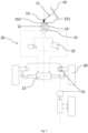
- this application provides an autonomous-driving hydraulic steering modification control system, including a steering wheel, a hydraulic steering mechanism and a turning wheel, the hydraulic steering mechanism being connected with the steering wheel and the turning wheel respectively, the steering wheel being connected with the hydraulic steering mechanism through a first rotating shaft and a second rotating shaft, one end of the first rotating shaft being connected with the steering wheel and the other end of the first rotating shaft being connected with one end of the second rotating shaft through a steering connector, the other end of the second rotating shaft being connected with the hydraulic steering mechanism, and a steering motor being arranged on the second rotating shaft and being configured to drive the hydraulic steering mechanism to rotate so as to make the turning wheel rotate.
- a preset included angle is formed between the first rotating shaft and the second rotating shaft.
- orientations or position relations indicated by terms such as “center”, “upper”, “lower”, “front”, “rear”, “left”, “right”, “vertical”, “horizontal”, “top”, “bottom”, “inner”, “outer”, “axial”, “radial” and “circumferential” are orientations or position relations shown based on the accompanying drawings and are only intended to conveniently describe the present disclosure and simplify the description but not to indicate or imply that a referred apparatus or element necessarily has a specific orientation and is constructed and operated in a specific orientation, so as not to be understood as a limitation on the present disclosure.
- first and second are only used for description instead of being understood as indicating or implying a relative significance or implicitly indicating the quantity of referred technical features. Therefore, a feature limited by “first” and “second” may explicitly or implicitly include one or more of this feature.
- a plurality of means two or more than two unless otherwise limited specifically and clearly.
- mount In the present disclosure, unless otherwise specified and limited clearly, terms such as “mount”, “connect”, “connected” and “fix” are to be understood in a broad sense, for example, it may be a fixed connection or detachable connection, or be integrated; it may be a direct connection, or an indirect connection through an intermediate medium, and may be an internal communication between two elements or an interactive relationship between the two elements. But it is noted that the direct connection indicates that two bodies that are connected are connected into a whole only through a connection structure without establishing a connection relation through a transition structure. Specific meanings of the above terms in the present disclosure may be understood by those ordinarily skilled in the art according to specific conditions.
- a first feature being "on” or “below” a second feature may be that the first feature is in direct contact with the second feature, or that the first feature is in indirect contact with the second feature through an intermediate medium.
- a description with reference to terms such as “one embodiment”, “some embodiments”, “example”, “specific example” or “some examples” means that a specific feature, structure, material or characteristic described with reference to the embodiment or example is included in at least one embodiment or example of the present disclosure.
- a schematic statement for the above terms is not necessarily for the same embodiment or example.
- the described specific feature, structure, material or characteristic may be combined in any one or more embodiments or example in a proper manner.
- this application provides an autonomous-driving hydraulic steering modification control system, including a steering wheel 10, a hydraulic steering mechanism 20 and a turning wheel 30; the hydraulic steering mechanism 20 is connected with the steering wheel 10 and the turning wheel 30 respectively; the steering wheel 10 is connected with the hydraulic steering mechanism 20 through a first rotating shaft 11 and a second rotating shaft 12; one end of the first rotating shaft 11 is connected with the steering wheel 10, the other end of the first rotating shaft is connected with one end of the second rotating shaft 12 through a steering connector 13, and the other end of the second rotating shaft 12 is connected with the hydraulic steering mechanism 20; and a steering motor 14 is arranged on the second rotating shaft 12 and is configured to drive the hydraulic steering mechanism 20 to rotate so as to make the turning wheel 30 rotate.
- this application by additionally arranging the steering motor 14 and making the steering motor act on the hydraulic steering mechanism 20 to make the turning wheel 30 rotate, autonomous driving can be achieved. Meanwhile, this application performs modification on the basis of an original vehicle, the turning wheel 30 may still be driven by the steering wheel 10 to rotate, application of manned driving is maintained, a modification flow may also be simplified, structural configuration may be simplified, cost is reduced, and the modification efficiency is improved.
- the steering connector 13 is arranged between the first rotating shaft 11 and the second rotating shaft 12, a user, while manipulating the steering wheel 10, may still use the steering motor 14 for proving an extra assistance force, and thus the error caused by the steering connector 13 can be compensated through a dual function of the steering wheel 10 and the steering motor 14.
- the steering motor 14 is additionally mounted between the steering wheel 10 and the hydraulic steering mechanism 20, modification on the original vehicle is small, implementation is convenient, modification cost is low, and the modification efficiency is high.
- the hydraulic steering mechanism 20, with reference to a related structure in the prior art may include, for example, a steering valve 21, a liquid storage tank 22, a hydraulic pump, a steering cylinder 23, a fluid pipeline and the like, and working principles of the various components may refer to a content in the prior art and are not described in detail here in this application.
- the steering motor can drive the steering valve 21 to act on the hydraulic steering mechanism 20 so as to make the hydraulic steering system work and thus drive the turning wheel 30 to rotate.
- a structure of the steering connector 13 may be, for example, any one of a steering knuckle, a cardan joint, a coupling assembly, a sprocket transmission mechanism, a gear transmission mechanism, a gear and rack transmission mechanism, and a worm wheel and worm transmission mechanism, which may be arranged according to actual demands and is not limited in this application.
- the steering motor 14 is a double-output-shaft motor.
- output shafts at two ends of the steering motor 14 may be directly coupled with the second rotating shaft 12, so on one hand, motor configuration can be simplified, and on the other hand, assembling can be simplified.
- the steering motor 14 may be arranged as a first-stage precision control
- the transmission mechanism may be arranged as a second-stage precision control
- the large gear 152 is driven by the pinion 151 for transmission
- the precision can be further improved, thus the turning angle precision of the turning wheel 30 is improved, and the turning wheel 30 may reach an ideal turning angle.
- the steering motor 14 is, for example, a servo motor, and a transmission ratio of the pinion 151 and the large gear 152 may be set according to actual demands, so as to meet the requirement for the steering precision.
- a preset included angle is formed between the first rotating shaft 11 and the second rotating shaft 12.
- the second rotating shaft 12 extends, for example, in a vertical direction, so as to facilitate compact configuration and meanwhile optimize a relative arrangement of the second rotating shaft and the hydraulic steering mechanism 20, so a transmission error from the steering motor 14 to the hydraulic steering mechanism 20 is reduced as much as possible.
- the first rotating shaft 11 is in bending connection with the second rotating shaft 12, for example, an obtuse-angled included angle is formed between the first rotating shaft 11 and the second rotating shaft 12, the first rotating shaft 11 extends towards the steering wheel 10, thus an angle of the steering wheel 10 may be more suitable for a manual use demand, and comfort of manual operation is improved.
- control system further includes a controller and a turning angle measurement apparatus 31, the turning angle measurement apparatus 31 is arranged on a steering shaft of the turning wheel 30, and the turning angle measurement apparatus 31 and the steering motor 14 are electrically connected with the controller respectively.
- the controller may be configured to obtain measurement data collected by the turning angle measurement apparatus 31 and obtain actual turning angle data of the turning wheel 30 according to the measurement data. Further, the controller may compare the expected turning angle data of the turning wheel 30 provided by the system with the actual turning angle data of the turning wheel 30 and perform processing such as corresponding calculation so as to obtain working parameters such as the expected turning angle and the expected rotating speed of the steering motor 14, therefore, the controller may control the steering motor 14 to act based on the working parameters such as the expected turning angle and the expected rotating speed of the steering motor 14, so as to control the turning wheel 30 to rotate, and meanwhile, the turning angle measurement apparatus 31 may continue measuring a current rotation of the turning wheel 30 and feed a measurement result back to the controller. Therefore, this application may implement closed-loop control and can guarantee that the turning wheel 30 reaches the ideal turning angle.
- the controller is, for example, an ECU.
- the turning angle measurement apparatus 31 is, for example, an angle encoder.
- this application may omit the closed-loop control, and the steering precision can be controlled to be within 1 degree, or even within 0.5 degree only by acting on the hydraulic steering mechanism 20 through the steering motor 14.
- the closed-loop control may be added, so as to guarantee that the turning wheel 30 reaches the ideal turning angle and improve the response speed, and thus it is adapted to a working condition with a higher requirement.
- this application further provides an autonomous-driving hydraulic steering modification control method
- the control method may be based on the above modification control system
- the control system includes a steering wheel 10, a hydraulic steering mechanism 20 and a turning wheel 30.
- the steering wheel 10 is connected with the hydraulic steering mechanism 20 through a first rotating shaft 11 and a second rotating shaft 12, a steering connector 13 is arranged between the first rotating shaft 11 and the second rotating shaft 12, and a steering motor 14 is arranged on the second rotating shaft 12.
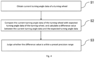
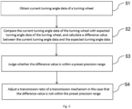
- the control system further includes a controller electrically connected with the steering motor 14. As shown in Fig. 4 , the control method includes the following steps:
- step S1 measurement data may be collected by using a turning angle measurement apparatus such as an encoder, and the controller may process the measurement data to obtain the current turning angle data of the turning wheel, namely, actual turning angle data of the turning wheel.
- a turning angle measurement apparatus such as an encoder
- the controller may also obtain the expected turning angle data of the turning wheel and calculate the difference value between the expected turning angle data and the actual turning angle data of the turning wheel obtained in step S1.
- the controller may judge whether system steering precision is within the preset precision range according to the above difference value result. For example, when the difference value between the actual turning angle data and the expected turning angle data of the turning wheel is less than 1 (may correspond to an angle of 1 degree), in order to meet the precision requirement, the difference value is within the preset precision range. Otherwise, when the difference value is not within the preset precision range, the controller may provide a prompt such as a warning.
- the above control method may reflect a modification achievement from application and data and provide a modification evaluation, and when the above difference value is not within the preset precision range, those of related skill may improve the precision control by adjusting a modification strategy, such as replacing a type of the steering motor 14, and adjusting the working parameters of the steering motor 14, so as to meet the situation that the difference value is controlled to be within the preset precision range in above step S3.
- a modification strategy such as replacing a type of the steering motor 14, and adjusting the working parameters of the steering motor 14, so as to meet the situation that the difference value is controlled to be within the preset precision range in above step S3.
- a transmission mechanism is arranged between the steering motor 14 and a second rotating shaft 12.
- the control method further includes: S4: a transmission ratio of the transmission mechanism is adjusted in the case that the difference value is not within the preset precision range.
- the transmission mechanism includes a pinion 151 connected with an output shaft of the steering motor 14 and a large gear 152 engaged with the pinion 151.
- the transmission ratio may be adjusted by substituting a pinion 151 with the different number of teeth and/or a large gear 152 with the different number of teeth, so that the above difference value range is reduced, and the above difference value is controlled to be within the preset precision range.
- a modification application effect may be known according to step S3, and when the modification does not meet the precision requirement of autonomous driving, the modification strategy may be adjusted according to step S4, and thus a modification effect is better improved.
- the transmission ratio is adjusted so as to correspond to different precisions, conveniently adapt to different working conditions and expand an application scene of autonomous driving.
- the turning wheel 30 is provided with an encoder; and the control method further includes:
- the controller such as an ECU, may collect the feedback turning angle data of the encoder and obtain the actual turning angle data of the turning angle 30 after processing, the controller further receives an instruction of the expected turning angle data of the turning wheel 30 sent by a main control unit and obtains the expected rotating speed and the expected turning angle data of the steering motor 14 according to the above two types of data, then the controller sends an action instruction/signal to the steering motor 14, the turning wheel 30 is driven by the hydraulic steering mechanism 20 to rotate, and meanwhile, the encoder feeds a current turning angle of the turning wheel 30 back to the controller, so as to implement closed-loop control over the turning angle of the turning wheel 30 till the turning angle is adjusted in place.
- the controller such as an ECU, may collect the feedback turning angle data of the encoder and obtain the actual turning angle data of the turning angle 30 after processing, the controller further receives an instruction of the expected turning angle data of the turning wheel 30 sent by a main control unit and obtains the expected rotating speed and the expected turning angle data of the steering motor 14 according to the above two types of
- Turning angle data of the turning wheel equals (feedback turning angle data of the encoder)*a, where a is a corresponding relationship between data of the encoder and an angle of the turning wheel.
- the expected rotating speed of the steering motor equals (an expected rotating speed of the turning wheel)*b; and an expected turning angle of the steering motor equals (an expected turning angle of the turning wheel)*b, where b is a relationship between an angle change of the steering motor and an angle change of the turning wheel.
- the parameter b may be obtained by (a maximum value of a turning angle of the steering wheel minus a minimum value of the turning angle of the steering wheel)/(a maximum value of the turning angle of the turning wheel minus a minimum value of the turning angle of the turning wheel).
Landscapes
- Engineering & Computer Science (AREA)
- Chemical & Material Sciences (AREA)
- Combustion & Propulsion (AREA)
- Transportation (AREA)
- Mechanical Engineering (AREA)
- Physics & Mathematics (AREA)
- Mathematical Physics (AREA)
- Steering Control In Accordance With Driving Conditions (AREA)
- Power Steering Mechanism (AREA)
Applications Claiming Priority (2)
| Application Number | Priority Date | Filing Date | Title |
|---|---|---|---|
| CN202211105656.0A CN115402404B (zh) | 2022-09-08 | 2022-09-08 | 一种自动驾驶液压转向改造控制系统及控制方法 |
| PCT/CN2023/117558 WO2024051786A1 (zh) | 2022-09-08 | 2023-09-07 | 一种自动驾驶液压转向改造控制系统及控制方法 |
Publications (4)
| Publication Number | Publication Date |
|---|---|
| EP4393792A1 true EP4393792A1 (de) | 2024-07-03 |
| EP4393792A4 EP4393792A4 (de) | 2025-03-19 |
| EP4393792B1 EP4393792B1 (de) | 2025-12-10 |
| EP4393792C0 EP4393792C0 (de) | 2025-12-10 |
Family
ID=84164889
Family Applications (1)
| Application Number | Title | Priority Date | Filing Date |
|---|---|---|---|
| EP23862480.3A Active EP4393792B1 (de) | 2022-09-08 | 2023-09-07 | Transformationssteuerungssystem für hydraulische lenkung mit autonomem fahren und steuerungsverfahren |
Country Status (7)
| Country | Link |
|---|---|
| US (1) | US20240409081A1 (de) |
| EP (1) | EP4393792B1 (de) |
| JP (1) | JP7618330B2 (de) |
| KR (1) | KR102748596B1 (de) |
| CN (1) | CN115402404B (de) |
| ES (1) | ES3058761T3 (de) |
| WO (1) | WO2024051786A1 (de) |
Families Citing this family (2)
| Publication number | Priority date | Publication date | Assignee | Title |
|---|---|---|---|---|
| CN115402404B (zh) * | 2022-09-08 | 2024-01-05 | 北京九曜智能科技有限公司 | 一种自动驾驶液压转向改造控制系统及控制方法 |
| NL2038993B1 (en) * | 2024-11-04 | 2025-05-23 | Univ Tianshui Normal | Hydraulic transformer |
Family Cites Families (14)
| Publication number | Priority date | Publication date | Assignee | Title |
|---|---|---|---|---|
| GB0407998D0 (en) * | 2004-04-07 | 2004-05-12 | Agco Gmbh & Co | Hydrostatic steering systems |
| JP4830569B2 (ja) | 2006-03-22 | 2011-12-07 | トヨタ自動車株式会社 | 車両の走行制御装置 |
| JP2008087672A (ja) | 2006-10-03 | 2008-04-17 | Jtekt Corp | 車両用操舵装置 |
| US8244434B2 (en) * | 2008-06-17 | 2012-08-14 | Agco Corporation | Methods and system for automatic user-configurable steering parameter control |
| CN105128929A (zh) * | 2015-09-21 | 2015-12-09 | 北京理工大学 | 一种智能化线控电液转向系统 |
| SE542907C2 (en) * | 2018-12-11 | 2020-09-15 | Scania Cv Ab | A method for determining hydraulic failure in a hybrid steering system, a control device, a hybrid steering system and a vehicle |
| CN112477977A (zh) * | 2019-09-12 | 2021-03-12 | 比亚迪股份有限公司 | 一种车辆助力转向装置及其控制方法 |
| CN114312987B (zh) * | 2020-09-09 | 2023-11-03 | 东风汽车有限公司 | 一种自动驾驶转向角度检测方法及电子设备 |
| CN213502564U (zh) * | 2020-10-30 | 2021-06-22 | 深兰人工智能(深圳)有限公司 | 一种线控转向系统及商用车 |
| CN114644037A (zh) * | 2020-12-21 | 2022-06-21 | 中车时代电动汽车股份有限公司 | 一种纯电动客车智能转向系统 |
| CN112722063B (zh) * | 2021-01-18 | 2024-04-30 | 北京九曜智能科技有限公司 | 一种液压转向系统闭环控制系统及控制方法 |
| CN113147888B (zh) * | 2021-04-26 | 2023-04-04 | 徐州重型机械有限公司 | 转向器、助力转向系统及起重机 |
| CN218367973U (zh) * | 2022-09-08 | 2023-01-24 | 北京九曜智能科技有限公司 | 一种液压转向传动系统 |
| CN115402404B (zh) * | 2022-09-08 | 2024-01-05 | 北京九曜智能科技有限公司 | 一种自动驾驶液压转向改造控制系统及控制方法 |
-
2022
- 2022-09-08 CN CN202211105656.0A patent/CN115402404B/zh active Active
-
2023
- 2023-09-07 WO PCT/CN2023/117558 patent/WO2024051786A1/zh not_active Ceased
- 2023-09-07 ES ES23862480T patent/ES3058761T3/es active Active
- 2023-09-07 US US18/701,927 patent/US20240409081A1/en active Pending
- 2023-09-07 JP JP2024525792A patent/JP7618330B2/ja active Active
- 2023-09-07 EP EP23862480.3A patent/EP4393792B1/de active Active
- 2023-09-07 KR KR1020247016769A patent/KR102748596B1/ko active Active
Also Published As
| Publication number | Publication date |
|---|---|
| EP4393792A4 (de) | 2025-03-19 |
| KR102748596B1 (ko) | 2025-01-03 |
| CN115402404A (zh) | 2022-11-29 |
| EP4393792B1 (de) | 2025-12-10 |
| ES3058761T3 (en) | 2026-03-12 |
| KR20240095256A (ko) | 2024-06-25 |
| EP4393792C0 (de) | 2025-12-10 |
| CN115402404B (zh) | 2024-01-05 |
| US20240409081A1 (en) | 2024-12-12 |
| JP2024540204A (ja) | 2024-10-31 |
| JP7618330B2 (ja) | 2025-01-21 |
| WO2024051786A1 (zh) | 2024-03-14 |
Similar Documents
| Publication | Publication Date | Title |
|---|---|---|
| EP4393792A1 (de) | Transformationssteuerungssystem für hydraulische lenkung mit autonomem fahren und steuerungsverfahren | |
| US10370028B2 (en) | Power steering device | |
| KR20200144973A (ko) | 스티어 바이 와이어식 조향장치 | |
| CN116374001B (zh) | 一种方向盘中位角度标定方法 | |
| US12116054B2 (en) | Steering device | |
| EP2610135A2 (de) | Hydraulisches Servolenksystem | |
| CN107215385A (zh) | 电动动力转向系统的转向扭矩补偿装置和方法 | |
| US12263897B2 (en) | Steering control system and steering control method | |
| US8783408B2 (en) | Hydraulic power steering system | |
| US7239972B2 (en) | Method for setting, in a motor vehicle electrical power steering system, the power steering torque set point | |
| CN114312987B (zh) | 一种自动驾驶转向角度检测方法及电子设备 | |
| US6292730B1 (en) | Speed ratio controller and control method of continuously transmisson | |
| US20110066327A1 (en) | Power steering apparatus | |
| CN218367973U (zh) | 一种液压转向传动系统 | |
| US20210155284A1 (en) | Electric power steering system | |
| US20210362775A1 (en) | Motor control device and steering system | |
| CN111366120A (zh) | 一种循环球转向器自由间隙的检测装置及其检测方法 | |
| JP3354099B2 (ja) | 負荷装置 | |
| JP4892995B2 (ja) | パワーステアリング装置 | |
| CN211651571U (zh) | 一种循环球转向器自由间隙的检测装置 | |
| JP2004279295A (ja) | パワーステアリング装置 | |
| CN114771645B (zh) | 一种电液组合自动转向装置及其控制方法 | |
| CN116323370B (zh) | 转向装置 | |
| JP2006044405A (ja) | 船舶用パワーステアリング装置 | |
| CN118419116A (zh) | 转向装置和车辆 |
Legal Events
| Date | Code | Title | Description |
|---|---|---|---|
| STAA | Information on the status of an ep patent application or granted ep patent |
Free format text: STATUS: THE INTERNATIONAL PUBLICATION HAS BEEN MADE |
|
| PUAI | Public reference made under article 153(3) epc to a published international application that has entered the european phase |
Free format text: ORIGINAL CODE: 0009012 |
|
| STAA | Information on the status of an ep patent application or granted ep patent |
Free format text: STATUS: REQUEST FOR EXAMINATION WAS MADE |
|
| 17P | Request for examination filed |
Effective date: 20240329 |
|
| AK | Designated contracting states |
Kind code of ref document: A1 Designated state(s): AL AT BE BG CH CY CZ DE DK EE ES FI FR GB GR HR HU IE IS IT LI LT LU LV MC ME MK MT NL NO PL PT RO RS SE SI SK SM TR |
|
| A4 | Supplementary search report drawn up and despatched |
Effective date: 20250214 |
|
| RIC1 | Information provided on ipc code assigned before grant |
Ipc: B62D 5/04 20060101ALI20250210BHEP Ipc: B62D 15/02 20060101ALI20250210BHEP Ipc: B62D 5/06 20060101AFI20250210BHEP |
|
| GRAP | Despatch of communication of intention to grant a patent |
Free format text: ORIGINAL CODE: EPIDOSNIGR1 |
|
| STAA | Information on the status of an ep patent application or granted ep patent |
Free format text: STATUS: GRANT OF PATENT IS INTENDED |
|
| DAV | Request for validation of the european patent (deleted) | ||
| DAX | Request for extension of the european patent (deleted) | ||
| INTG | Intention to grant announced |
Effective date: 20250725 |
|
| GRAS | Grant fee paid |
Free format text: ORIGINAL CODE: EPIDOSNIGR3 |
|
| GRAA | (expected) grant |
Free format text: ORIGINAL CODE: 0009210 |
|
| STAA | Information on the status of an ep patent application or granted ep patent |
Free format text: STATUS: THE PATENT HAS BEEN GRANTED |
|
| AK | Designated contracting states |
Kind code of ref document: B1 Designated state(s): AL AT BE BG CH CY CZ DE DK EE ES FI FR GB GR HR HU IE IS IT LI LT LU LV MC ME MK MT NL NO PL PT RO RS SE SI SK SM TR |
|
| REG | Reference to a national code |
Ref country code: CH Ref legal event code: F10 Free format text: ST27 STATUS EVENT CODE: U-0-0-F10-F00 (AS PROVIDED BY THE NATIONAL OFFICE) Effective date: 20251210 Ref country code: GB Ref legal event code: FG4D |
|
| REG | Reference to a national code |
Ref country code: DE Ref legal event code: R096 Ref document number: 602023009646 Country of ref document: DE |
|
| REG | Reference to a national code |
Ref country code: IE Ref legal event code: FG4D |
|
| U01 | Request for unitary effect filed |
Effective date: 20260108 |
|
| U07 | Unitary effect registered |
Designated state(s): AT BE BG DE DK EE FI FR IT LT LU LV MT NL PT RO SE SI Effective date: 20260113 |
|
| REG | Reference to a national code |
Ref country code: ES Ref legal event code: FG2A Ref document number: 3058761 Country of ref document: ES Kind code of ref document: T3 Effective date: 20260312 |
|
| PG25 | Lapsed in a contracting state [announced via postgrant information from national office to epo] |
Ref country code: NO Free format text: LAPSE BECAUSE OF FAILURE TO SUBMIT A TRANSLATION OF THE DESCRIPTION OR TO PAY THE FEE WITHIN THE PRESCRIBED TIME-LIMIT Effective date: 20260310 |
|
| PG25 | Lapsed in a contracting state [announced via postgrant information from national office to epo] |
Ref country code: HR Free format text: LAPSE BECAUSE OF FAILURE TO SUBMIT A TRANSLATION OF THE DESCRIPTION OR TO PAY THE FEE WITHIN THE PRESCRIBED TIME-LIMIT Effective date: 20251210 |
|
| PG25 | Lapsed in a contracting state [announced via postgrant information from national office to epo] |
Ref country code: RS Free format text: LAPSE BECAUSE OF FAILURE TO SUBMIT A TRANSLATION OF THE DESCRIPTION OR TO PAY THE FEE WITHIN THE PRESCRIBED TIME-LIMIT Effective date: 20260310 |