EP4393801A1 - Elektrischer motorroller batteriefach - Google Patents
Elektrischer motorroller batteriefach Download PDFInfo
- Publication number
- EP4393801A1 EP4393801A1 EP23220570.8A EP23220570A EP4393801A1 EP 4393801 A1 EP4393801 A1 EP 4393801A1 EP 23220570 A EP23220570 A EP 23220570A EP 4393801 A1 EP4393801 A1 EP 4393801A1
- Authority
- EP
- European Patent Office
- Prior art keywords
- compartment
- jacking
- component
- electric scooter
- receiving groove
- Prior art date
- Legal status (The legal status is an assumption and is not a legal conclusion. Google has not performed a legal analysis and makes no representation as to the accuracy of the status listed.)
- Pending
Links
Images






Classifications
-
- B—PERFORMING OPERATIONS; TRANSPORTING
- B62—LAND VEHICLES FOR TRAVELLING OTHERWISE THAN ON RAILS
- B62J—CYCLE SADDLES OR SEATS; AUXILIARY DEVICES OR ACCESSORIES SPECIALLY ADAPTED TO CYCLES AND NOT OTHERWISE PROVIDED FOR, e.g. ARTICLE CARRIERS OR CYCLE PROTECTORS
- B62J43/00—Arrangements of batteries
- B62J43/10—Arrangements of batteries for propulsion
- B62J43/13—Arrangements of batteries for propulsion on rider-propelled cycles with additional electric propulsion
-
- B—PERFORMING OPERATIONS; TRANSPORTING
- B62—LAND VEHICLES FOR TRAVELLING OTHERWISE THAN ON RAILS
- B62J—CYCLE SADDLES OR SEATS; AUXILIARY DEVICES OR ACCESSORIES SPECIALLY ADAPTED TO CYCLES AND NOT OTHERWISE PROVIDED FOR, e.g. ARTICLE CARRIERS OR CYCLE PROTECTORS
- B62J43/00—Arrangements of batteries
- B62J43/10—Arrangements of batteries for propulsion
- B62J43/16—Arrangements of batteries for propulsion on motorcycles or the like
-
- B—PERFORMING OPERATIONS; TRANSPORTING
- B62—LAND VEHICLES FOR TRAVELLING OTHERWISE THAN ON RAILS
- B62J—CYCLE SADDLES OR SEATS; AUXILIARY DEVICES OR ACCESSORIES SPECIALLY ADAPTED TO CYCLES AND NOT OTHERWISE PROVIDED FOR, e.g. ARTICLE CARRIERS OR CYCLE PROTECTORS
- B62J43/00—Arrangements of batteries
- B62J43/20—Arrangements of batteries characterised by the mounting
-
- B—PERFORMING OPERATIONS; TRANSPORTING
- B62—LAND VEHICLES FOR TRAVELLING OTHERWISE THAN ON RAILS
- B62J—CYCLE SADDLES OR SEATS; AUXILIARY DEVICES OR ACCESSORIES SPECIALLY ADAPTED TO CYCLES AND NOT OTHERWISE PROVIDED FOR, e.g. ARTICLE CARRIERS OR CYCLE PROTECTORS
- B62J43/00—Arrangements of batteries
- B62J43/20—Arrangements of batteries characterised by the mounting
- B62J43/28—Arrangements of batteries characterised by the mounting hidden within the cycle frame
-
- B—PERFORMING OPERATIONS; TRANSPORTING
- B62—LAND VEHICLES FOR TRAVELLING OTHERWISE THAN ON RAILS
- B62K—CYCLES; CYCLE FRAMES; CYCLE STEERING DEVICES; RIDER-OPERATED TERMINAL CONTROLS SPECIALLY ADAPTED FOR CYCLES; CYCLE AXLE SUSPENSIONS; CYCLE SIDECARS, FORECARS, OR THE LIKE
- B62K3/00—Bicycles
- B62K3/002—Bicycles without a seat, i.e. the rider operating the vehicle in a standing position, e.g. non-motorized scooters; non-motorized scooters with skis or runners
Definitions
- Some existing electric scooters often come with a specially designed battery component.
- the battery component is usually a single piece, which is very large and inconvenient to carry.
- the battery components of the most existing electric scooters are usually fixed in the frame of the scooter and is not easy to disassemble. Therefore, existing electric scooters are inconvenient when it comes to charging.
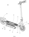
- Embodiments of the present disclosure provide electric scooters.
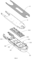
- the electric scooter since the electric scooter is provided with a compartment body and a compartment cover pivotally mounted to the compartment body, the battery component may be disassembled and replaced more easily.
- the compartment body or the compartment cover is provided with a jacking component, the problem of poor assembly of the compartment body and the compartment cover caused by deformation due to excessive length of the deck may be effectively avoided.
- the jacking component includes a jacking post and a first elastic element cooperating with the jacking post, and when the compartment cover is closed, the jacking post abuts against the compartment body or the compartment cover, while the first elastic element is elastic deformed under the action of the jacking post.
- one end of the jacking post away from the first elastic element is provided with a boss, and the boss is in a convex arc shape, so that the contact between the boss and the compartment body or the compartment cover is a line contact or a point contact.
- the positioning groove is provided with a guiding portion to guide the jacking post to slide out of the positioning groove.
- the compartment cover is provided with a receiving groove
- the jacking component is disposed in the receiving groove
- the first elastic element is located between a bottom wall of the receiving groove and the jacking post.
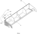
- the jacking component 14 includes a jacking post 141 and a first elastic element 142 that cooperates with the jacking post 141.
- the jacking post 141 abuts against the compartment body 121 or the compartment cover 122.
- one end of the first elastic element 142 that faces away from the jacking post 141 abuts against the compartment cover 122 or the compartment body 121, and the first elastic element 142 deforms under the action of the jacking post 141.
- a boss 1411 is provided at one end of the jacking post 141 that is away from the first elastic element 142.
- the boss 1411 is in a convex arc shape, so that the contact between the boss 1411 and the compartment body 121 or the compartment cover 122 is a line contact or a point contact, thereby reducing the friction between the jacking post 141 and the compartment body 121 or the compartment covers 122, which makes it easier for the user to open or close the compartment cover 122.
- the compartment body 121 or the compartment cover 122 that is abutted by the jacking post 141 is provided with a positioning groove 111 that matches the jacking post 141.
- a guiding portion 1111 is provided in the positioning groove 111 to guide the jacking post 141 to slide out of the positioning groove 111.
- the jacking component 14 is provided on the compartment cover 122, and the positioning groove 111 is provided on the compartment body 121.
- the compartment cover 122 is also provided with a receiving groove 1221, and the jacking component 14 is disposed in the receiving groove 1221.
- the first elastic element 142 is located between a bottom wall 1222 of the receiving groove 1221 and the jacking post 141.
- a limiting wall 1224 is provided at an opening 1223 of the receiving groove 1221.
- the jacking post 141 also includes a main body 1412, and the boss 1411 protrudes outward from one end of the main body 1412. In a direction perpendicular to the extending direction of the receiving groove 1221, the width of the main body 1412 is greater than the width of the boss 1411, and the width of the boss 1411 is not greater than the width of the opening 1223.
- the limiting wall 1224 cooperates with the main body 1412, so that the main body 1412 is located in the receiving groove 1221 and the boss 1411 can pass through the opening 1223 to the outside of the receiving groove 1221, so as to support and abut against the side wall of the compartment body 121.
- the receiving groove 1221 is provided with an assembly opening 1225, a mounting groove 1226, and a limiting plate 1227.
- the jacking component 14 enters the receiving groove 1221 through the assembly opening 1225, and the limiting plate 1227 is mounted in the mounting groove 1226, thus sealing the assembly opening 1225 to prevent the jacking component 14 from sliding out of the receiving groove 1221 through the assembly opening 1225.
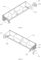
- the number of the jacking components 14 is two, and these two jacking components 14 are respectively located on two sides of the compartment cover 122. However, it can be understood that in other exemplary embodiments, the number and location of the jacking components 14 can be determined as needed.
- the compartment body 121 is also provided with a mounting cavity 1213, and the shaft cover 123 is received in the mounting cavity 1213.
- the shaft cover 123 is provided with a guiding structure
- the compartment cover 122 is provided with a directing structure that matches the guiding structure of the shaft cover 123.
- the shaft cover 123 includes a cover plate 1231, and the cover plate 1231 is provided with a shaft hole 1232 and the guiding structure.
- the guiding structure includes a first guiding wall 1233 protruding outward from the cover plate 1231, and the compartment cover 122 is provided with a pivot 1214 that cooperates with the shaft hole 1232.
- the directing structure includes a first directing wall 1215 that cooperates with the first guiding wall 1233. Due to the existence of the first guiding wall 1233 and the first directing wall 1215 cooperating with the first guiding wall 1233, the compartment cover 122 may be better supported.
- a first abutting surface 1235 is also provided between the first guiding wall 1233 and the second guiding wall 1234, and a second abutting surface 1217 is provided between the first directing wall 1215, and the second directing wall 1216.
- the first abutting surface 1235 cooperates with the second abutting surface 1217.
- the compartment cover 122 may be better limited between a pair of the shaft covers 123, and the shaking of the compartment cover 122 is effectively avoided, thereby avoiding the problem of poor assembly of the compartment body 121 and the compartment cover 122 that is caused by the shaking of the compartment cover 122.
- the shaft cover 123 is also provided with a first limiting arm 1236
- the compartment cover 122 is provided with a second limiting arm 1218 that cooperates with the first limiting arm 1236.
- the first limiting arm 1236 cooperates with the second limiting arm 1218 to limit the rotation range of the compartment cover 122.
- the electric scooter 100 is provided with a compartment body 121, a shaft cover 123 fixedly mounted to the compartment body 121, and a compartment cover 122 pivotally mounted to the shaft cover 123. Therefore, it is relatively convenient to disassemble and replace the battery component 40. Also, because the shaft cover 123 is provided with a guiding structure, and the compartment cover 122 is provided with a directing structure that cooperates with the guiding structure, it is possible to effectively avoid the smoothness issue of the opening and closing of the compartment cover 122 caused by deformation due to excessive length of the deck.
Landscapes
- Engineering & Computer Science (AREA)
- Mechanical Engineering (AREA)
- Automatic Cycles, And Cycles In General (AREA)
Applications Claiming Priority (2)
| Application Number | Priority Date | Filing Date | Title |
|---|---|---|---|
| CN202223572707.9U CN220147489U (zh) | 2022-12-29 | 2022-12-29 | 电动滑板车 |
| CN202223540936.2U CN219406734U (zh) | 2022-12-29 | 2022-12-29 | 电动滑板车 |
Publications (1)
| Publication Number | Publication Date |
|---|---|
| EP4393801A1 true EP4393801A1 (de) | 2024-07-03 |
Family
ID=89474770
Family Applications (1)
| Application Number | Title | Priority Date | Filing Date |
|---|---|---|---|
| EP23220570.8A Pending EP4393801A1 (de) | 2022-12-29 | 2023-12-28 | Elektrischer motorroller batteriefach |
Country Status (2)
| Country | Link |
|---|---|
| US (1) | US20240217609A1 (de) |
| EP (1) | EP4393801A1 (de) |
Citations (4)
| Publication number | Priority date | Publication date | Assignee | Title |
|---|---|---|---|---|
| WO2018068277A1 (zh) * | 2016-10-13 | 2018-04-19 | 深圳易马达科技有限公司 | 电动滑板车 |
| WO2021027961A1 (zh) * | 2019-08-15 | 2021-02-18 | 纳恩博(北京)科技有限公司 | 电动滑板车 |
| DE102019007915A1 (de) * | 2019-11-13 | 2021-05-20 | Pascher + Heinz GmbH | Elektrisch antreibbarer Scooter und Aufladesystem |
| DE102021109289A1 (de) * | 2021-04-14 | 2022-10-20 | Walberg Urban Electrics Gmbh | Roller |
Family Cites Families (2)
| Publication number | Priority date | Publication date | Assignee | Title |
|---|---|---|---|---|
| WO2011148125A1 (en) * | 2010-05-24 | 2011-12-01 | H Grossman Ltd | Scooter comprising a space for a battery |
| US8979110B2 (en) * | 2012-03-16 | 2015-03-17 | Specialized Bicycle Components, Inc. | Bicycle with battery mount |
-
2023
- 2023-12-28 EP EP23220570.8A patent/EP4393801A1/de active Pending
- 2023-12-28 US US18/398,155 patent/US20240217609A1/en active Pending
Patent Citations (4)
| Publication number | Priority date | Publication date | Assignee | Title |
|---|---|---|---|---|
| WO2018068277A1 (zh) * | 2016-10-13 | 2018-04-19 | 深圳易马达科技有限公司 | 电动滑板车 |
| WO2021027961A1 (zh) * | 2019-08-15 | 2021-02-18 | 纳恩博(北京)科技有限公司 | 电动滑板车 |
| DE102019007915A1 (de) * | 2019-11-13 | 2021-05-20 | Pascher + Heinz GmbH | Elektrisch antreibbarer Scooter und Aufladesystem |
| DE102021109289A1 (de) * | 2021-04-14 | 2022-10-20 | Walberg Urban Electrics Gmbh | Roller |
Also Published As
| Publication number | Publication date |
|---|---|
| US20240217609A1 (en) | 2024-07-04 |
Similar Documents
| Publication | Publication Date | Title |
|---|---|---|
| JP2969119B1 (ja) | 引き出し回転操作型扉用ロックハンドル装置 | |
| US6748631B2 (en) | Hinge assembly and wrist mounting-type electronic apparatus utilizing hinge assembly | |
| US6176040B1 (en) | Slotted lever device for keeping an automotive door in an open position | |
| EP4393801A1 (de) | Elektrischer motorroller batteriefach | |
| US7437803B2 (en) | Grip handle type door handle apparatus | |
| US12203301B2 (en) | Lock lever and opening/closing device | |
| CN103080449B (zh) | 杂物箱装置 | |
| CN220147489U (zh) | 电动滑板车 | |
| JP2969118B1 (ja) | 引き出し回転操作型扉用ロックハンドル装置 | |
| EP2119856A1 (de) | Deckelöffnungsbetätigungsvorrichtung | |
| JP3907249B2 (ja) | 引戸構造 | |
| JPH0639029Y2 (ja) | ドアの取付構造 | |
| WO2020161098A1 (en) | Load carrier for a vehicle | |
| JP3907058B2 (ja) | 扉用ロックハンドル装置 | |
| JPH09306449A (ja) | 電池収納装置 | |
| CN219431569U (zh) | 一种简易的执手锁结构 | |
| JP2592991Y2 (ja) | 自動車用開閉装置 | |
| JP3029644U (ja) | 引出回転型扉用ロックハンドル装置 | |
| JP4061698B2 (ja) | 蓋機構を有する電子機器 | |
| JP2000013045A (ja) | 開閉扉の破損防止機構と電子機器 | |
| WO2024216779A1 (zh) | 二次锁结构、车架组件及电动车 | |
| JP4139099B2 (ja) | ロック装置 | |
| JP2623229B2 (ja) | 扉係止装置 | |
| JPH0630976U (ja) | テープカセット | |
| JPH0630974U (ja) | テープカセット |
Legal Events
| Date | Code | Title | Description |
|---|---|---|---|
| PUAI | Public reference made under article 153(3) epc to a published international application that has entered the european phase |
Free format text: ORIGINAL CODE: 0009012 |
|
| STAA | Information on the status of an ep patent application or granted ep patent |
Free format text: STATUS: THE APPLICATION HAS BEEN PUBLISHED |
|
| AK | Designated contracting states |
Kind code of ref document: A1 Designated state(s): AL AT BE BG CH CY CZ DE DK EE ES FI FR GB GR HR HU IE IS IT LI LT LU LV MC ME MK MT NL NO PL PT RO RS SE SI SK SM TR |
|
| STAA | Information on the status of an ep patent application or granted ep patent |
Free format text: STATUS: REQUEST FOR EXAMINATION WAS MADE |
|
| 17P | Request for examination filed |
Effective date: 20241219 |
|
| GRAP | Despatch of communication of intention to grant a patent |
Free format text: ORIGINAL CODE: EPIDOSNIGR1 |
|
| STAA | Information on the status of an ep patent application or granted ep patent |
Free format text: STATUS: GRANT OF PATENT IS INTENDED |
|
| INTG | Intention to grant announced |
Effective date: 20260223 |
|
| GRAS | Grant fee paid |
Free format text: ORIGINAL CODE: EPIDOSNIGR3 |
|
| GRAA | (expected) grant |
Free format text: ORIGINAL CODE: 0009210 |
|
| STAA | Information on the status of an ep patent application or granted ep patent |
Free format text: STATUS: THE PATENT HAS BEEN GRANTED |