EP4393825A1 - Système de conditionnement de carburant - Google Patents
Système de conditionnement de carburant Download PDFInfo
- Publication number
- EP4393825A1 EP4393825A1 EP22383300.5A EP22383300A EP4393825A1 EP 4393825 A1 EP4393825 A1 EP 4393825A1 EP 22383300 A EP22383300 A EP 22383300A EP 4393825 A1 EP4393825 A1 EP 4393825A1
- Authority
- EP
- European Patent Office
- Prior art keywords
- fuel
- heat
- conditioning system
- conduct
- recovery circuit
- Prior art date
- Legal status (The legal status is an assumption and is not a legal conclusion. Google has not performed a legal analysis and makes no representation as to the accuracy of the status listed.)
- Pending
Links
Images
Classifications
-
- F—MECHANICAL ENGINEERING; LIGHTING; HEATING; WEAPONS; BLASTING
- F02—COMBUSTION ENGINES; HOT-GAS OR COMBUSTION-PRODUCT ENGINE PLANTS
- F02C—GAS-TURBINE PLANTS; AIR INTAKES FOR JET-PROPULSION PLANTS; CONTROLLING FUEL SUPPLY IN AIR-BREATHING JET-PROPULSION PLANTS
- F02C7/00—Features, components parts, details or accessories, not provided for in, or of interest apart form groups F02C1/00 - F02C6/00; Air intakes for jet-propulsion plants
- F02C7/22—Fuel supply systems
- F02C7/224—Heating fuel before feeding to the burner
-
- B—PERFORMING OPERATIONS; TRANSPORTING
- B64—AIRCRAFT; AVIATION; COSMONAUTICS
- B64D—EQUIPMENT FOR FITTING IN OR TO AIRCRAFT; FLIGHT SUITS; PARACHUTES; ARRANGEMENT OR MOUNTING OF POWER PLANTS OR PROPULSION TRANSMISSIONS IN AIRCRAFT
- B64D37/00—Arrangements in connection with fuel supply for power plant
- B64D37/30—Fuel systems for specific fuels
-
- B—PERFORMING OPERATIONS; TRANSPORTING
- B64—AIRCRAFT; AVIATION; COSMONAUTICS
- B64D—EQUIPMENT FOR FITTING IN OR TO AIRCRAFT; FLIGHT SUITS; PARACHUTES; ARRANGEMENT OR MOUNTING OF POWER PLANTS OR PROPULSION TRANSMISSIONS IN AIRCRAFT
- B64D37/00—Arrangements in connection with fuel supply for power plant
- B64D37/34—Conditioning fuel, e.g. heating
-
- B—PERFORMING OPERATIONS; TRANSPORTING
- B64—AIRCRAFT; AVIATION; COSMONAUTICS
- B64D—EQUIPMENT FOR FITTING IN OR TO AIRCRAFT; FLIGHT SUITS; PARACHUTES; ARRANGEMENT OR MOUNTING OF POWER PLANTS OR PROPULSION TRANSMISSIONS IN AIRCRAFT
- B64D41/00—Power installations for auxiliary purposes
-
- B—PERFORMING OPERATIONS; TRANSPORTING
- B64—AIRCRAFT; AVIATION; COSMONAUTICS
- B64D—EQUIPMENT FOR FITTING IN OR TO AIRCRAFT; FLIGHT SUITS; PARACHUTES; ARRANGEMENT OR MOUNTING OF POWER PLANTS OR PROPULSION TRANSMISSIONS IN AIRCRAFT
- B64D41/00—Power installations for auxiliary purposes
- B64D2041/002—Mounting arrangements for auxiliary power units (APU's)
-
- F—MECHANICAL ENGINEERING; LIGHTING; HEATING; WEAPONS; BLASTING
- F05—INDEXING SCHEMES RELATING TO ENGINES OR PUMPS IN VARIOUS SUBCLASSES OF CLASSES F01-F04
- F05D—INDEXING SCHEME FOR ASPECTS RELATING TO NON-POSITIVE-DISPLACEMENT MACHINES OR ENGINES, GAS-TURBINES OR JET-PROPULSION PLANTS
- F05D2260/00—Function
- F05D2260/20—Heat transfer, e.g. cooling
-
- F—MECHANICAL ENGINEERING; LIGHTING; HEATING; WEAPONS; BLASTING
- F17—STORING OR DISTRIBUTING GASES OR LIQUIDS
- F17C—VESSELS FOR CONTAINING OR STORING COMPRESSED, LIQUEFIED OR SOLIDIFIED GASES; FIXED-CAPACITY GAS-HOLDERS; FILLING VESSELS WITH, OR DISCHARGING FROM VESSELS, COMPRESSED, LIQUEFIED, OR SOLIDIFIED GASES
- F17C9/00—Methods or apparatus for discharging liquefied or solidified gases from vessels not under pressure
- F17C9/02—Methods or apparatus for discharging liquefied or solidified gases from vessels not under pressure with change of state, e.g. vaporisation
- F17C9/04—Recovery of thermal energy
Definitions
- the fuel provided to the fuel inlet is in a liquid phase and previously stored at specific temperature and pressure conditions.
- the fuel is stored at a temperature in a range from 20K to 30K.
- said fuel is injected at a temperature comprised in said temperature range.
- the power unit further comprises heating means connected to the evaporating means and configured to supply heat to the fuel of the fuel conduct.
- the heating means also comprise a fuel inlet and a fuel outlet.
- the heating means are to be considered as a support to the conditioning system of the invention which, in fully operative mode, is to be turned off and the conditioning system is providing the required energy/heat to the fuel of the fuel conduct by means of the evaporating means only.
- the heating means energy provided to the fuel conduct is decreasing at the same time the energy provided to the fuel conduct by the evaporating means is increasing. That is, the balance between the heating means and the evaporating means is considered as an active control of the conditioning system, more particularly of the fuel of the power unit.
- heating the fuel by means of the heating means avoids the conditions of a cold start of the engine which is considered the worst start-up conditions for any embodiment of the power unit, such as Auxiliary Power Units or propellers.
- cold start of the engine is the worst start-up conditions for the power unit since more fuel is necessary for the engine to start and, at the same time, it is when more heat is required from the heating means.
- the conditioning system of the present invention also comprises a heat recovery circuit.
- the heat recovery circuit comprises a heat exchanger, recovering heat from the exhaust gases of the power unit, which is in fluid communication with the evaporating means of the power unit.
- the heat recovery circuit comprises a working fluid which is to be understood as the fluid being recirculated inside the heat recovery circuit.
- the heat recovery circuit is to be considered as an independent and a closed circuit where the fuel and the working fluid never enter in direct contact or mingle.
- the heat exchanger has null or low performance rates in the start-up phase of the power unit but still requires to reach its operative conditions as quick as possible in order to optimize the heat recovery circuit performance and, therefore, the whole power unit performance.
- the heat recovery circuit is configured for transferring heat from the working fluid to the fluid of the fluid conduct by means of the evaporating means, said heat recovery circuit, since it is a closed circuit, is physically uncoupled from the fuel conduct and, thus, uncoupled from the engine. Therefore, if either the fuel conduct of the power unit or the heat recovery circuit is/are damaged, there is no need to uncoupled one from the other in order to perform maintenance or repairing of either one of the elements of the power unit or either one of the elements of the heat recovery circuit. Furthermore, the heat recovery circuit is operable independently of the engine rotation and is also operable on request, before or after operating the engine of the power unit.
- the first pumping means is mechanically connected to the engine of the power unit.
- the heat recovery circuit further comprises a second bypass conduct configured to connect a third portion of the heat recovery circuit and a fourth portion of the heat recovery circuit, wherein the third portion is located between the evaporating means and the first portion of the heat recovery circuit, and wherein the fourth portion of the heat recovery circuit is located between the second portion of the heat recovery circuit and the evaporating means.
- the heating means are located downstream the evaporating means and upstream the engine.
- the second heat exchanger is located downstream the first heat exchanger which is the point where the working fluid is at its highest temperature.
- the second heat exchanger is also located downstream the fuel inlet which is the point where the fuel is at its lowest temperature in the conditioning system of the invention.
- the second heat exchanger provides a temperature delta between the working fluid and the fuel which provides a change of the specific volume of the fuel at this specific location of the fuel conduct in order to start the phase change, that is, from liquid form or supercritical fluid form (SCF) into low temperature gas form.
- SCF supercritical fluid form
- the fluid of the fluid conduct is hydrogen (H2) and / or the working fluid of the heat recovery circuit is Nitrogen (N2), Helium (He), or a mixture of Nitrogen (N2) and Helium (He), and / or ethylene glycol water (EGW).
- H2 hydrogen
- the working fluid of the heat recovery circuit is Nitrogen (N2), Helium (He), or a mixture of Nitrogen (N2) and Helium (He), and / or ethylene glycol water (EGW).
- the fluid of the fluid conduct is pure hydrogen.
- the conditioning system to encapsulate some particular elements of the conditioning system, such as the evaporating means and the heating means or the second pumping means and the valve, secures the rest of the conditioning system in case of leakage of fuel from the fuel conduct where these critical elements are located.
- the present invention provides an aircraft comprising a conditioning system according to the first inventive aspect of the invention.
- the invention provides a method for conditioning fuel of conditioning system according to the first inventive aspect of the invention, when the aircraft is on ground or in flight, the method comprising the following steps:
- the heating means are located downstream the evaporating means.
- the temperature reference value T FH is lower or equal to the fuel temperature reference value T FL .
- step g) of the present method the heating means are stopped once the heat recovery circuit is able to maintain, by itself, the temperature of the fuel of the fuel conduct at the temperature reference value T FH .
- T FH the temperature reference value at the outlet of the evaporating means is 288K.
- the fuel pressure reference value P F is 1.25 MPa.
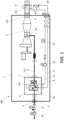
- the fuel inlet (2) is configured to supply liquid fuel to the fuel conduct (3) and the fuel conduct (3) connect the fuel inlet (2) to the engine (4).
- the engine (4) comprises an inlet (4.1) and an outlet (4.2) connected to the power unit outlet (5).
- the power unit outlet (5) is configured to exhaust gases out of the engine (4).
- the engine (4) is a gas turbine.
Landscapes
- Engineering & Computer Science (AREA)
- Aviation & Aerospace Engineering (AREA)
- Chemical & Material Sciences (AREA)
- Combustion & Propulsion (AREA)
- Mechanical Engineering (AREA)
- General Engineering & Computer Science (AREA)
- Central Heating Systems (AREA)
- Feeding And Controlling Fuel (AREA)
Priority Applications (5)
| Application Number | Priority Date | Filing Date | Title |
|---|---|---|---|
| EP22383300.5A EP4393825A1 (fr) | 2022-12-28 | 2022-12-28 | Système de conditionnement de carburant |
| CA3221414A CA3221414A1 (fr) | 2022-12-28 | 2023-11-28 | Systeme de conditionnement de carburant |
| US18/525,143 US20240218832A1 (en) | 2022-12-28 | 2023-11-30 | Fuel conditioning system |
| JP2023203048A JP2024095550A (ja) | 2022-12-28 | 2023-11-30 | 燃料コンディショニングシステム |
| CN202311662108.2A CN118254956A (zh) | 2022-12-28 | 2023-12-06 | 燃料调节系统 |
Applications Claiming Priority (1)
| Application Number | Priority Date | Filing Date | Title |
|---|---|---|---|
| EP22383300.5A EP4393825A1 (fr) | 2022-12-28 | 2022-12-28 | Système de conditionnement de carburant |
Publications (1)
| Publication Number | Publication Date |
|---|---|
| EP4393825A1 true EP4393825A1 (fr) | 2024-07-03 |
Family
ID=84980886
Family Applications (1)
| Application Number | Title | Priority Date | Filing Date |
|---|---|---|---|
| EP22383300.5A Pending EP4393825A1 (fr) | 2022-12-28 | 2022-12-28 | Système de conditionnement de carburant |
Country Status (5)
| Country | Link |
|---|---|
| US (1) | US20240218832A1 (fr) |
| EP (1) | EP4393825A1 (fr) |
| JP (1) | JP2024095550A (fr) |
| CN (1) | CN118254956A (fr) |
| CA (1) | CA3221414A1 (fr) |
Cited By (1)
| Publication number | Priority date | Publication date | Assignee | Title |
|---|---|---|---|---|
| FR3167408A1 (fr) * | 2024-10-14 | 2026-04-17 | Safran Aircraft Engines | Dispositif de régulation de la pression d’une boucle caloporteuse pour système d’alimentation en hydrogène d’une turbomachine |
Families Citing this family (3)
| Publication number | Priority date | Publication date | Assignee | Title |
|---|---|---|---|---|
| FR3166665A1 (fr) * | 2024-09-25 | 2026-03-27 | Safran Aircraft Engines | Systeme d’alimentation en hydrogene d’une turbomachine et dispositif de regulation en temperature d’un tel systeme d’alimentation en hydrogene |
| FR3166667A1 (fr) * | 2024-09-25 | 2026-03-27 | Safran Aircraft Engines | Systeme d’alimentation en hydrogene d’une turbomachine et dispositif de regulation en temperature d’un tel systeme d’alimentation en hydrogene |
| FR3166666A1 (fr) * | 2024-09-25 | 2026-03-27 | Safran Aircraft Engines | Systeme d’alimentation en hydrogene d’une turbomachine et dispositif de regulation en temperature d’un tel systeme d’alimentation en hydrogene |
Citations (5)
| Publication number | Priority date | Publication date | Assignee | Title |
|---|---|---|---|---|
| JP2013019378A (ja) * | 2011-07-13 | 2013-01-31 | Mitsubishi Heavy Ind Ltd | ガスタービン設備、及びその燃料温度管理方法 |
| US20150321767A1 (en) * | 2012-12-28 | 2015-11-12 | General Electric Company | System for temperature and actuation control and method of controlling fluid temperatures in an aircraft |
| US20150337730A1 (en) * | 2012-12-28 | 2015-11-26 | General Electric Company | Turbine engine assemblies |
| US20210301720A1 (en) * | 2020-03-27 | 2021-09-30 | United Technologies Corporation | Supercritical co2 cycle for gas turbine engines having supplemental cooling |
| US20220099299A1 (en) * | 2020-09-30 | 2022-03-31 | Rolls-Royce Plc | Fuel injection |
Family Cites Families (7)
| Publication number | Priority date | Publication date | Assignee | Title |
|---|---|---|---|---|
| DE10228335B3 (de) * | 2002-06-25 | 2004-02-12 | Siemens Ag | Abhitzedampferzeuger mit Hilfsdampferzeugung |
| US7487642B2 (en) * | 2005-11-01 | 2009-02-10 | General Electric Comapny | Methods and apparatus for operating gas turbine engines |
| US9014791B2 (en) * | 2009-04-17 | 2015-04-21 | Echogen Power Systems, Llc | System and method for managing thermal issues in gas turbine engines |
| JP2016502622A (ja) * | 2012-11-30 | 2016-01-28 | ゼネラル・エレクトリック・カンパニイ | タービンエンジンアセンブリおよび二系統燃料航空機システム |
| US9765691B2 (en) * | 2012-12-28 | 2017-09-19 | General Electric Company | Turbine engine assembly and dual fuel aircraft system |
| GB2573131A (en) * | 2018-04-25 | 2019-10-30 | Hieta Tech Limited | Combined heat and power system |
| US11161622B2 (en) * | 2018-11-02 | 2021-11-02 | General Electric Company | Fuel oxygen reduction unit |
-
2022
- 2022-12-28 EP EP22383300.5A patent/EP4393825A1/fr active Pending
-
2023
- 2023-11-28 CA CA3221414A patent/CA3221414A1/fr active Pending
- 2023-11-30 US US18/525,143 patent/US20240218832A1/en active Pending
- 2023-11-30 JP JP2023203048A patent/JP2024095550A/ja active Pending
- 2023-12-06 CN CN202311662108.2A patent/CN118254956A/zh active Pending
Patent Citations (5)
| Publication number | Priority date | Publication date | Assignee | Title |
|---|---|---|---|---|
| JP2013019378A (ja) * | 2011-07-13 | 2013-01-31 | Mitsubishi Heavy Ind Ltd | ガスタービン設備、及びその燃料温度管理方法 |
| US20150321767A1 (en) * | 2012-12-28 | 2015-11-12 | General Electric Company | System for temperature and actuation control and method of controlling fluid temperatures in an aircraft |
| US20150337730A1 (en) * | 2012-12-28 | 2015-11-26 | General Electric Company | Turbine engine assemblies |
| US20210301720A1 (en) * | 2020-03-27 | 2021-09-30 | United Technologies Corporation | Supercritical co2 cycle for gas turbine engines having supplemental cooling |
| US20220099299A1 (en) * | 2020-09-30 | 2022-03-31 | Rolls-Royce Plc | Fuel injection |
Cited By (1)
| Publication number | Priority date | Publication date | Assignee | Title |
|---|---|---|---|---|
| FR3167408A1 (fr) * | 2024-10-14 | 2026-04-17 | Safran Aircraft Engines | Dispositif de régulation de la pression d’une boucle caloporteuse pour système d’alimentation en hydrogène d’une turbomachine |
Also Published As
| Publication number | Publication date |
|---|---|
| JP2024095550A (ja) | 2024-07-10 |
| CN118254956A (zh) | 2024-06-28 |
| CA3221414A1 (fr) | 2024-06-28 |
| US20240218832A1 (en) | 2024-07-04 |
Similar Documents
| Publication | Publication Date | Title |
|---|---|---|
| US20240218832A1 (en) | Fuel conditioning system | |
| CN114645780B (zh) | 带燃料冷却的热管理系统 | |
| US20160025339A1 (en) | Energy-efficient and controlled vaporization of cryofuels for aircraft engines | |
| US11808204B2 (en) | Circuit for supplying fuel to an aeronautical cryogenic turbomachine and associated method | |
| US8430361B2 (en) | Method and device enabling a rocket engine pump to be driven by an internal combustion engine | |
| US10006363B2 (en) | System and method for aviation electric power production | |
| US20130186059A1 (en) | Dual fuel aircraft system and method for operating same | |
| EP3760853B1 (fr) | Installation d'aéronef pour fournir de l'air sous pression | |
| US20230250754A1 (en) | Multiple turboexpander system having selective coupler | |
| US12466575B2 (en) | Conditioning system for an aircraft | |
| EP2925981A2 (fr) | Ensemble moteur de turbine et système d'aéronef à double combustible | |
| WO2014105325A1 (fr) | Système de carburant cryogénique et procédé de distribution de carburant dans un aéronef | |
| WO2012045029A1 (fr) | Système de commande de moteur d'avion bicarburant et son procédé de fonctionnement | |
| US12479591B2 (en) | System for conditioning fuel for supplying an aircraft turbomachine, aircraft and method of use | |
| EP4303417B1 (fr) | Moteur à hydrogène électrique hybride pour aéronef | |
| US12365477B1 (en) | Hydrogen fuelled aircraft propulsion system | |
| US20250084791A1 (en) | System and method for conditioning fuel for an air-breathing hydrogen engine | |
| US20210001991A1 (en) | Air management system | |
| EP4647591A1 (fr) | Système et procédé de carburant d'aéronef | |
| EP4484289B1 (fr) | Aéronef comprenant un système de soufflante de cabine |
Legal Events
| Date | Code | Title | Description |
|---|---|---|---|
| PUAI | Public reference made under article 153(3) epc to a published international application that has entered the european phase |
Free format text: ORIGINAL CODE: 0009012 |
|
| STAA | Information on the status of an ep patent application or granted ep patent |
Free format text: STATUS: THE APPLICATION HAS BEEN PUBLISHED |
|
| AK | Designated contracting states |
Kind code of ref document: A1 Designated state(s): AL AT BE BG CH CY CZ DE DK EE ES FI FR GB GR HR HU IE IS IT LI LT LU LV MC ME MK MT NL NO PL PT RO RS SE SI SK SM TR |
|
| STAA | Information on the status of an ep patent application or granted ep patent |
Free format text: STATUS: REQUEST FOR EXAMINATION WAS MADE |
|
| 17P | Request for examination filed |
Effective date: 20241217 |
|
| STAA | Information on the status of an ep patent application or granted ep patent |
Free format text: STATUS: EXAMINATION IS IN PROGRESS |
|
| 17Q | First examination report despatched |
Effective date: 20250807 |