EP4393855A1 - Dispositif de transport d'échantillon et procédé de transport d'échantillon - Google Patents
Dispositif de transport d'échantillon et procédé de transport d'échantillon Download PDFInfo
- Publication number
- EP4393855A1 EP4393855A1 EP22860918.6A EP22860918A EP4393855A1 EP 4393855 A1 EP4393855 A1 EP 4393855A1 EP 22860918 A EP22860918 A EP 22860918A EP 4393855 A1 EP4393855 A1 EP 4393855A1
- Authority
- EP
- European Patent Office
- Prior art keywords
- conveying
- conveyance
- determined
- conveyance path
- container
- Prior art date
- Legal status (The legal status is an assumption and is not a legal conclusion. Google has not performed a legal analysis and makes no representation as to the accuracy of the status listed.)
- Pending
Links
Images


Classifications
-
- B—PERFORMING OPERATIONS; TRANSPORTING
- B65—CONVEYING; PACKING; STORING; HANDLING THIN OR FILAMENTARY MATERIAL
- B65G—TRANSPORT OR STORAGE DEVICES, e.g. CONVEYORS FOR LOADING OR TIPPING, SHOP CONVEYOR SYSTEMS OR PNEUMATIC TUBE CONVEYORS
- B65G54/00—Non-mechanical conveyors not otherwise provided for
- B65G54/02—Non-mechanical conveyors not otherwise provided for electrostatic, electric, or magnetic
-
- G—PHYSICS
- G01—MEASURING; TESTING
- G01N—INVESTIGATING OR ANALYSING MATERIALS BY DETERMINING THEIR CHEMICAL OR PHYSICAL PROPERTIES
- G01N35/00—Automatic analysis not limited to methods or materials provided for in any single one of groups G01N1/00 - G01N33/00; Handling materials therefor
- G01N35/02—Automatic analysis not limited to methods or materials provided for in any single one of groups G01N1/00 - G01N33/00; Handling materials therefor using a plurality of sample containers moved by a conveyor system past one or more treatment or analysis stations
- G01N35/026—Automatic analysis not limited to methods or materials provided for in any single one of groups G01N1/00 - G01N33/00; Handling materials therefor using a plurality of sample containers moved by a conveyor system past one or more treatment or analysis stations having blocks or racks of reaction cells or cuvettes
-
- G—PHYSICS
- G01—MEASURING; TESTING
- G01N—INVESTIGATING OR ANALYSING MATERIALS BY DETERMINING THEIR CHEMICAL OR PHYSICAL PROPERTIES
- G01N35/00—Automatic analysis not limited to methods or materials provided for in any single one of groups G01N1/00 - G01N33/00; Handling materials therefor
- G01N35/00584—Control arrangements for automatic analysers
- G01N35/0092—Scheduling
-
- G—PHYSICS
- G01—MEASURING; TESTING
- G01N—INVESTIGATING OR ANALYSING MATERIALS BY DETERMINING THEIR CHEMICAL OR PHYSICAL PROPERTIES
- G01N35/00—Automatic analysis not limited to methods or materials provided for in any single one of groups G01N1/00 - G01N33/00; Handling materials therefor
- G01N35/02—Automatic analysis not limited to methods or materials provided for in any single one of groups G01N1/00 - G01N33/00; Handling materials therefor using a plurality of sample containers moved by a conveyor system past one or more treatment or analysis stations
- G01N35/04—Details of the conveyor system
-
- G—PHYSICS
- G01—MEASURING; TESTING
- G01N—INVESTIGATING OR ANALYSING MATERIALS BY DETERMINING THEIR CHEMICAL OR PHYSICAL PROPERTIES
- G01N35/00—Automatic analysis not limited to methods or materials provided for in any single one of groups G01N1/00 - G01N33/00; Handling materials therefor
- G01N35/00584—Control arrangements for automatic analysers
- G01N35/00722—Communications; Identification
- G01N2035/00891—Displaying information to the operator
-
- G—PHYSICS
- G01—MEASURING; TESTING
- G01N—INVESTIGATING OR ANALYSING MATERIALS BY DETERMINING THEIR CHEMICAL OR PHYSICAL PROPERTIES
- G01N35/00—Automatic analysis not limited to methods or materials provided for in any single one of groups G01N1/00 - G01N33/00; Handling materials therefor
- G01N35/02—Automatic analysis not limited to methods or materials provided for in any single one of groups G01N1/00 - G01N33/00; Handling materials therefor using a plurality of sample containers moved by a conveyor system past one or more treatment or analysis stations
- G01N35/04—Details of the conveyor system
- G01N2035/0401—Sample carriers, cuvettes or reaction vessels
- G01N2035/0406—Individual bottles or tubes
-
- G—PHYSICS
- G01—MEASURING; TESTING
- G01N—INVESTIGATING OR ANALYSING MATERIALS BY DETERMINING THEIR CHEMICAL OR PHYSICAL PROPERTIES
- G01N35/00—Automatic analysis not limited to methods or materials provided for in any single one of groups G01N1/00 - G01N33/00; Handling materials therefor
- G01N35/02—Automatic analysis not limited to methods or materials provided for in any single one of groups G01N1/00 - G01N33/00; Handling materials therefor using a plurality of sample containers moved by a conveyor system past one or more treatment or analysis stations
- G01N35/04—Details of the conveyor system
- G01N2035/0474—Details of actuating means for conveyors or pipettes
- G01N2035/0477—Magnetic
-
- G—PHYSICS
- G01—MEASURING; TESTING
- G01N—INVESTIGATING OR ANALYSING MATERIALS BY DETERMINING THEIR CHEMICAL OR PHYSICAL PROPERTIES
- G01N35/00—Automatic analysis not limited to methods or materials provided for in any single one of groups G01N1/00 - G01N33/00; Handling materials therefor
- G01N35/02—Automatic analysis not limited to methods or materials provided for in any single one of groups G01N1/00 - G01N33/00; Handling materials therefor using a plurality of sample containers moved by a conveyor system past one or more treatment or analysis stations
- G01N35/04—Details of the conveyor system
- G01N2035/0474—Details of actuating means for conveyors or pipettes
- G01N2035/0491—Position sensing, encoding; closed-loop control
Definitions
- a sample analysis system for clinical testing performs a test for a specified analysis item on the sample (sample) such as blood, plasma, serum, urine, and other body fluids.
- the sample analysis system connects devices having a plurality of functions and automatically executes the processing of each process. That is, to streamline the work in an examination room, an analysis unit (analysis process) that performs a plurality of analyses such as biochemistry and immunology and a pretreatment unit (pretreatment process) that performs a plurality of pretreatments required for the analyses, and the like, are connected via a conveyance line and used as a single sample analysis system.
- analysis unit analysis process
- pretreatment process pretreatment process
- the laboratory specimen delivery system described in PTL 1 does not describe how to determine the factor that causes a decrease in the conveyance speed.
- the cause of decrease in conveyance speed is thought to be deterioration of the conveying surface, such as scraping of the conveying surface, in addition to dirt on the conveying surface.
- An object of the present invention is to provide a sample conveying device and a sample conveying method that are capable of estimating a factor that causes a decrease in a conveyance speed of a sample.
- the present invention is configured as follows.
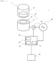
- a sample conveying device including a conveying container that includes a magnet or magnetic material and contains a sample, a conveyance unit in which a plurality of magnetic poles, each of which includes a core and a coil, are arranged and the conveying container is moved on a conveying surface, a control unit that controls a voltage applied to the plurality of magnetic poles, detects a position of the conveying container on the conveying surface, and controls movement of the conveying container, in which the control unit detects an amplitude of a current flowing through the coil of each of the plurality of magnetic poles when the conveying container approaches each of the plurality of the magnetic poles, and determines deterioration of the conveying surface based on the detected amplitude of the current.
- a sample conveying method including a conveying container that includes a magnet or magnetic material and contains a sample, and a conveyance unit in which a plurality of magnetic poles, each of which includes a core and a coil, are arranged and the conveying container is moved on a conveying surface, controlling a voltage applied to the plurality of magnetic poles, detecting a position of the conveying container on the conveying surface, and controlling movement of the conveying container, the method including detecting an amplitude of a current flowing through the coil of each of the plurality of magnetic poles when the conveying container approaches each of the plurality of the magnetic poles, and determining deterioration of the conveying surface based on the detected amplitude of the current.
- the sample conveying device and the sample conveying method that are capable of estimating the factor that causes the decrease in the conveyance speed of the sample.
- a thickness of the conveying surface 12 is constant so that the thrust force generated by the magnetic pole 25 (coil 21) is optimal for conveyance.
- deterioration such as scraping of the upper surface of the conveying surface 12 may occur.
- the magnetic pole 25a attracts the permanent magnet 10 at time ta.
- the current amplitude at the timing when the position of each of the magnetic pole 25a, 25b, 25c, and 25d was detected is stored in the storing unit 43 of the control unit 40 and compared by the operation unit 41, thereby making it possible to detect a change in state due to scraping or the like on the upper surface of the conveying surface 12.
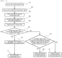
- step 108 the operation unit 41 determines whether the current amplitude of the coil on the conveyance path was within the threshold value during a time that the current amplitude should be within the threshold value.
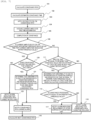
- Example 3 is an example in which processing is executed in the sample conveying device 1 when it is determined that there is an abnormality on the upper surface of the conveying surface 12.
- the overall configuration of the sample conveying device 1 is the same as that in Example 1, and thus illustration and detailed description thereof will be omitted.
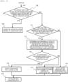
- Example 3 will be described using Fig. 5 .
- Fig. 5 is an operation flowchart of the control unit 40.
- Example 3 the processing when the determination result in step 108 is No is different from the example illustrated in Fig. 4 , and the other steps are the same. Therefore, the steps when the determination result in step 108 is No will be described.
- step 108 when the current amplitude of the coil 21 of the magnetic pole 25 on the conveyance path exceeds the threshold value and it is detected that there is an abnormality on the upper surface of the conveying surface 12 (when the determination result is No), the operation unit 41 determines whether the conveyance path used for conveyance does not include a path that cannot be excluded (step 111).
- conveyance paths that have a specific function in the system exist.
- the conveyance paths include a conveyance path in which a sensor for reading an ID of the conveying container 11 is disposed, and a conveyance path that serves as an entrance and exit for the analysis device and system itself. The conveying container 11 cannot be allowed to bypass such conveyance paths.
- step 111 when the conveyance path that cannot be excluded is not included, among the magnetic poles 25 used for the conveyance, the magnetic pole 25 whose current amplitude exceeds the threshold value and the magnetic poles 25 in front (on the upstream side) thereof are determined to be unusable as the conveyance path and are registered (stored in the storing unit 43) (step 112). That is, the magnetic pole 25 (coil 21) disposed at a position corresponding to the conveying surface 12, where it determined that there is the deterioration, and the magnetic pole 25 (coil 21) disposed upstream thereof are excluded from the conveyance path of the conveying container 11.
- the magnetic pole 25 (coil 21) whose current amplitude exceeds the threshold value is the magnetic pole 25 (coil 21) disposed at a position corresponding to the conveying surface 12, where it determined that there is the deterioration.
- the operation unit 41 calculates the time required for conveyance (estimated conveyance time). That is, a processing capacity of the conveying container 11 in the conveyance unit can be calculated from the time required for conveyance in one conveying container 11.
- the processing capacity of the conveying container 11 indicates the number of conveying containers 11 that one conveyance unit can process per unit time.
- the processing capacity required for the conveyance unit varies depending on the position of the conveyance unit in the system.
- step 112 when the conveyance path having deterioration is registered as unusable, the operation unit 41 calculates the conveyance path under a new restriction (restriction that excludes the conveyance path having deterioration). Then, the processing capacity of the conveyance unit is calculated from the time required for conveyance. The operation unit 41 determines whether the newly calculated conveyance processing capacity is equal to or greater than a threshold value required for the conveyance unit (step 113) .
- step 113 when the conveyance processing capacity is equal to or greater than the threshold value, since it is possible to change the conveyance path to a conveyance path obtained by excluding the conveying surface 12 having deterioration, the operation unit 41 notifies the user by displaying a conveyance path change alarm on the display unit 60 (step 115). Then, the next conveyance path is calculated (step 116).
- step 113 when the conveyance processing capacity is less than the threshold value, since the upper surface of the conveying surface 12 having deterioration needs to be replaced and used, the operation unit 41 notifies the user by displaying a replacement alarm indicating that the upper surface of the conveying surface 12 having deterioration of the conveyance unit needs to be replaced on the display unit 60 (step 117). Then, the next conveyance path is calculated (step 116).
- Example 3 it is possible to provide the sample conveying device and the sample conveying method that can notify the user of change of the conveyance path or replacement of the upper surface of the conveying surface 12 when it is determined that there is an abnormality on the upper surface of the conveying surface 12, in addition to being able to obtain the same effects as in Example 1.
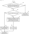
- Example 4 is an example in which the sample conveying device 1 executes processing when the conveyance time of the conveying container 11 exceeds the conveyance time calculated by the operation unit 41, an abnormality detection is performed on the upper surface of the conveying surface 12, and it is determined that there is no abnormality on the upper surface of the conveying surface 12 as described in Example 2.
- the overall configuration of the sample conveying device 1 is the same as that in Example 1, and thus illustration and detailed description thereof will be omitted.
- Fig. 6 is an operation flowchart of the control unit 40.
- Example 4 the processing when the determination result in step 108 is No is different from the example illustrated in Fig. 4 , and the other steps are the same. Therefore, the steps when the determination result in step 108 is No will be described.
- step 108 when it is determined that the current amplitude of the coil 21 of the magnetic pole 25 on the conveyance path is within the threshold value and there is no abnormality on the upper surface of the conveying surface 12, the operation unit 41 determines whether the conveyance path used for conveyance does not include the path that cannot be excluded (step 120).
- step 120 when it is determined that the path that cannot be excluded is included, the conveyance path is not excluded, and an alarm indicating that the conveyance path cannot be excluded is displayed on the display unit 60 to notify the user (step 123). Then, the next conveyance path is calculated (step 124).
- Example 5 the sample conveying device 1 in Example 5 will be described.
- steps 106 and 107 in Example 2 are omitted, and the process proceeds from step 105 to step 108.
- steps 111 to 113 and 115 to 118 in Example 3 are executed.
- steps 120 to 123 in Example 4 are executed, and step 116 is executed.
- Example 5 According to Example 5, the effects of Example 3 and the effects of Example 4 can be obtained.
Landscapes
- Chemical & Material Sciences (AREA)
- General Health & Medical Sciences (AREA)
- Life Sciences & Earth Sciences (AREA)
- Health & Medical Sciences (AREA)
- Analytical Chemistry (AREA)
- Biochemistry (AREA)
- Physics & Mathematics (AREA)
- General Physics & Mathematics (AREA)
- Immunology (AREA)
- Pathology (AREA)
- Chemical Kinetics & Catalysis (AREA)
- Non-Mechanical Conveyors (AREA)
- Automatic Analysis And Handling Materials Therefor (AREA)
Applications Claiming Priority (2)
| Application Number | Priority Date | Filing Date | Title |
|---|---|---|---|
| JP2021136584 | 2021-08-24 | ||
| PCT/JP2022/021902 WO2023026622A1 (fr) | 2021-08-24 | 2022-05-30 | Dispositif de transport d'échantillon et procédé de transport d'échantillon |
Publications (2)
| Publication Number | Publication Date |
|---|---|
| EP4393855A1 true EP4393855A1 (fr) | 2024-07-03 |
| EP4393855A4 EP4393855A4 (fr) | 2025-07-09 |
Family
ID=85321761
Family Applications (1)
| Application Number | Title | Priority Date | Filing Date |
|---|---|---|---|
| EP22860918.6A Pending EP4393855A4 (fr) | 2021-08-24 | 2022-05-30 | Dispositif de transport d'échantillon et procédé de transport d'échantillon |
Country Status (5)
| Country | Link |
|---|---|
| US (1) | US20250085304A1 (fr) |
| EP (1) | EP4393855A4 (fr) |
| JP (1) | JP7640716B2 (fr) |
| CN (1) | CN117677851A (fr) |
| WO (1) | WO2023026622A1 (fr) |
Families Citing this family (2)
| Publication number | Priority date | Publication date | Assignee | Title |
|---|---|---|---|---|
| WO2025057539A1 (fr) * | 2023-09-12 | 2025-03-20 | 株式会社日立ハイテク | Dispositif de transport d'échantillon |
| JP2025182599A (ja) * | 2024-06-03 | 2025-12-15 | 株式会社日立ハイテク | 搬送装置、及びそれを備えた検体分析システム、検体前処理装置、並びに搬送装置での異常検出方法 |
Family Cites Families (6)
| Publication number | Priority date | Publication date | Assignee | Title |
|---|---|---|---|---|
| EP2927695B1 (fr) * | 2014-03-31 | 2018-08-22 | Roche Diagniostics GmbH | Système de distribution d'échantillons et système d'automatisation de laboratoire |
| EP2995958A1 (fr) * | 2014-09-15 | 2016-03-16 | Roche Diagniostics GmbH | Procédé pour faire fonctionner un système de réseau de distribution d'échantillons de laboratoire, système de distribution d' échantillons de laboratoire et système d'automatisation de laboratoire |
| JP7300281B2 (ja) * | 2019-03-08 | 2023-06-29 | 株式会社日立ハイテク | 搬送装置、およびそれを備えた検体分析システム、検体前処理装置、ならびに被搬送体の搬送方法 |
| JP7304219B2 (ja) * | 2019-07-02 | 2023-07-06 | 株式会社日立ハイテク | 搬送装置 |
| JP7744363B2 (ja) * | 2020-05-11 | 2025-09-25 | エフ ホフマン-ラ ロッシュ アクチェン ゲゼルシャフト | 分配システム |
| JP7427114B2 (ja) * | 2020-12-23 | 2024-02-02 | 株式会社日立ハイテク | 検体搬送装置、および検体の搬送方法 |
-
2022
- 2022-05-30 US US18/580,133 patent/US20250085304A1/en active Pending
- 2022-05-30 CN CN202280051184.7A patent/CN117677851A/zh active Pending
- 2022-05-30 EP EP22860918.6A patent/EP4393855A4/fr active Pending
- 2022-05-30 WO PCT/JP2022/021902 patent/WO2023026622A1/fr not_active Ceased
- 2022-05-30 JP JP2023543697A patent/JP7640716B2/ja active Active
Also Published As
| Publication number | Publication date |
|---|---|
| WO2023026622A1 (fr) | 2023-03-02 |
| JP7640716B2 (ja) | 2025-03-05 |
| US20250085304A1 (en) | 2025-03-13 |
| EP4393855A4 (fr) | 2025-07-09 |
| CN117677851A (zh) | 2024-03-08 |
| JPWO2023026622A1 (fr) | 2023-03-02 |
Similar Documents
| Publication | Publication Date | Title |
|---|---|---|
| EP3905515B1 (fr) | Dispositif de transport, système d'analyse d'échantillon et dispositif de prétraitement d'échantillon le comprenant, et procédé de transport d'échantillon à transporter | |
| CN113939997B (zh) | 输送装置 | |
| EP4393855A1 (fr) | Dispositif de transport d'échantillon et procédé de transport d'échantillon | |
| EP4269295B1 (fr) | Dispositif de transport d'échantillons et procédé de transport d'échantillons | |
| US12411149B2 (en) | Specimen transport device, specimen analysis system, specimen pretreatment system, and specimen transport method | |
| EP4472061A1 (fr) | Dispositif de transport et procédé de transport | |
| US12565389B2 (en) | Sample conveyance system and sample conveyance method | |
| EP4101794A1 (fr) | Système de transport d'éprouvette et procédé de transport d'éprouvette | |
| EP4269296B1 (fr) | Dispositif de transport de spécimen | |
| EP4339141A1 (fr) | Dispositif de transport d'échantillon, système d'analyse d'échantillon et procédé de transport d'échantillon | |
| EP4685091A1 (fr) | Dispositif de transport et procédé de transport | |
| JP2026045905A (ja) | 電磁式検体搬送装置、検体分析システム及び検体前処理装置 | |
| EP4335799A1 (fr) | Dispositif de transport d'échantillon, système d'analyse d'échantillon et système de prétraitement d'échantillon | |
| EP4641213A1 (fr) | Porte-échantillon, dispositif de transport et procédé de transport de porte-échantillon | |
| EP4418528A1 (fr) | Dispositif de transport | |
| JP2025182599A (ja) | 搬送装置、及びそれを備えた検体分析システム、検体前処理装置、並びに搬送装置での異常検出方法 |
Legal Events
| Date | Code | Title | Description |
|---|---|---|---|
| STAA | Information on the status of an ep patent application or granted ep patent |
Free format text: STATUS: THE INTERNATIONAL PUBLICATION HAS BEEN MADE |
|
| PUAI | Public reference made under article 153(3) epc to a published international application that has entered the european phase |
Free format text: ORIGINAL CODE: 0009012 |
|
| STAA | Information on the status of an ep patent application or granted ep patent |
Free format text: STATUS: REQUEST FOR EXAMINATION WAS MADE |
|
| 17P | Request for examination filed |
Effective date: 20240319 |
|
| AK | Designated contracting states |
Kind code of ref document: A1 Designated state(s): AL AT BE BG CH CY CZ DE DK EE ES FI FR GB GR HR HU IE IS IT LI LT LU LV MC MK MT NL NO PL PT RO RS SE SI SK SM TR |
|
| DAV | Request for validation of the european patent (deleted) | ||
| DAX | Request for extension of the european patent (deleted) | ||
| A4 | Supplementary search report drawn up and despatched |
Effective date: 20250612 |
|
| RIC1 | Information provided on ipc code assigned before grant |
Ipc: G01N 35/04 20060101ALI20250605BHEP Ipc: B65G 54/02 20060101AFI20250605BHEP |
|
| STAA | Information on the status of an ep patent application or granted ep patent |
Free format text: STATUS: EXAMINATION IS IN PROGRESS |
|
| 17Q | First examination report despatched |
Effective date: 20251008 |