EP4394120A1 - Lave-linge séchant intégré - Google Patents
Lave-linge séchant intégré Download PDFInfo
- Publication number
- EP4394120A1 EP4394120A1 EP22863510.8A EP22863510A EP4394120A1 EP 4394120 A1 EP4394120 A1 EP 4394120A1 EP 22863510 A EP22863510 A EP 22863510A EP 4394120 A1 EP4394120 A1 EP 4394120A1
- Authority
- EP
- European Patent Office
- Prior art keywords
- moisture
- rotary wheel
- absorbing
- dehumidifying
- housing
- Prior art date
- Legal status (The legal status is an assumption and is not a legal conclusion. Google has not performed a legal analysis and makes no representation as to the accuracy of the status listed.)
- Pending
Links
Images





Classifications
-
- D—TEXTILES; PAPER
- D06—TREATMENT OF TEXTILES OR THE LIKE; LAUNDERING; FLEXIBLE MATERIALS NOT OTHERWISE PROVIDED FOR
- D06F—LAUNDERING, DRYING, IRONING, PRESSING OR FOLDING TEXTILE ARTICLES
- D06F39/00—Details of washing machines not specific to a single type of machines covered by groups D06F9/00 - D06F27/00
- D06F39/20—Arrangements for water recovery
-
- D—TEXTILES; PAPER
- D06—TREATMENT OF TEXTILES OR THE LIKE; LAUNDERING; FLEXIBLE MATERIALS NOT OTHERWISE PROVIDED FOR
- D06F—LAUNDERING, DRYING, IRONING, PRESSING OR FOLDING TEXTILE ARTICLES
- D06F18/00—Washing machines having receptacles, stationary for washing purposes, and having further drying means
-
- D—TEXTILES; PAPER
- D06—TREATMENT OF TEXTILES OR THE LIKE; LAUNDERING; FLEXIBLE MATERIALS NOT OTHERWISE PROVIDED FOR
- D06F—LAUNDERING, DRYING, IRONING, PRESSING OR FOLDING TEXTILE ARTICLES
- D06F29/00—Combinations of a washing machine with other separate apparatus in a common frame or the like, e.g. with rinsing apparatus
- D06F29/005—Combinations of a washing machine with other separate apparatus in a common frame or the like, e.g. with rinsing apparatus the other separate apparatus being a drying appliance
-
- D—TEXTILES; PAPER
- D06—TREATMENT OF TEXTILES OR THE LIKE; LAUNDERING; FLEXIBLE MATERIALS NOT OTHERWISE PROVIDED FOR
- D06F—LAUNDERING, DRYING, IRONING, PRESSING OR FOLDING TEXTILE ARTICLES
- D06F34/00—Details of control systems for washing machines, washer-dryers or laundry dryers
- D06F34/14—Arrangements for detecting or measuring specific parameters
- D06F34/26—Condition of the drying air, e.g. air humidity or temperature
-
- D—TEXTILES; PAPER
- D06—TREATMENT OF TEXTILES OR THE LIKE; LAUNDERING; FLEXIBLE MATERIALS NOT OTHERWISE PROVIDED FOR
- D06F—LAUNDERING, DRYING, IRONING, PRESSING OR FOLDING TEXTILE ARTICLES
- D06F39/00—Details of washing machines not specific to a single type of machines covered by groups D06F9/00 - D06F27/00
-
- D—TEXTILES; PAPER
- D06—TREATMENT OF TEXTILES OR THE LIKE; LAUNDERING; FLEXIBLE MATERIALS NOT OTHERWISE PROVIDED FOR
- D06F—LAUNDERING, DRYING, IRONING, PRESSING OR FOLDING TEXTILE ARTICLES
- D06F39/00—Details of washing machines not specific to a single type of machines covered by groups D06F9/00 - D06F27/00
- D06F39/04—Heating arrangements
-
- D—TEXTILES; PAPER
- D06—TREATMENT OF TEXTILES OR THE LIKE; LAUNDERING; FLEXIBLE MATERIALS NOT OTHERWISE PROVIDED FOR
- D06F—LAUNDERING, DRYING, IRONING, PRESSING OR FOLDING TEXTILE ARTICLES
- D06F39/00—Details of washing machines not specific to a single type of machines covered by groups D06F9/00 - D06F27/00
- D06F39/10—Filtering arrangements
-
- D—TEXTILES; PAPER
- D06—TREATMENT OF TEXTILES OR THE LIKE; LAUNDERING; FLEXIBLE MATERIALS NOT OTHERWISE PROVIDED FOR
- D06F—LAUNDERING, DRYING, IRONING, PRESSING OR FOLDING TEXTILE ARTICLES
- D06F58/00—Domestic laundry dryers
- D06F58/02—Domestic laundry dryers having dryer drums rotating about a horizontal axis
-
- D—TEXTILES; PAPER
- D06—TREATMENT OF TEXTILES OR THE LIKE; LAUNDERING; FLEXIBLE MATERIALS NOT OTHERWISE PROVIDED FOR
- D06F—LAUNDERING, DRYING, IRONING, PRESSING OR FOLDING TEXTILE ARTICLES
- D06F58/00—Domestic laundry dryers
- D06F58/02—Domestic laundry dryers having dryer drums rotating about a horizontal axis
- D06F58/04—Details
- D06F58/08—Driving arrangements
-
- D—TEXTILES; PAPER
- D06—TREATMENT OF TEXTILES OR THE LIKE; LAUNDERING; FLEXIBLE MATERIALS NOT OTHERWISE PROVIDED FOR
- D06F—LAUNDERING, DRYING, IRONING, PRESSING OR FOLDING TEXTILE ARTICLES
- D06F58/00—Domestic laundry dryers
- D06F58/10—Drying cabinets or drying chambers having heating or ventilating means
-
- D—TEXTILES; PAPER
- D06—TREATMENT OF TEXTILES OR THE LIKE; LAUNDERING; FLEXIBLE MATERIALS NOT OTHERWISE PROVIDED FOR
- D06F—LAUNDERING, DRYING, IRONING, PRESSING OR FOLDING TEXTILE ARTICLES
- D06F58/00—Domestic laundry dryers
- D06F58/20—General details of domestic laundry dryers
- D06F58/206—Heat pump arrangements
-
- D—TEXTILES; PAPER
- D06—TREATMENT OF TEXTILES OR THE LIKE; LAUNDERING; FLEXIBLE MATERIALS NOT OTHERWISE PROVIDED FOR
- D06F—LAUNDERING, DRYING, IRONING, PRESSING OR FOLDING TEXTILE ARTICLES
- D06F58/00—Domestic laundry dryers
- D06F58/20—General details of domestic laundry dryers
- D06F58/22—Lint collecting arrangements
-
- D—TEXTILES; PAPER
- D06—TREATMENT OF TEXTILES OR THE LIKE; LAUNDERING; FLEXIBLE MATERIALS NOT OTHERWISE PROVIDED FOR
- D06F—LAUNDERING, DRYING, IRONING, PRESSING OR FOLDING TEXTILE ARTICLES
- D06F58/00—Domestic laundry dryers
- D06F58/20—General details of domestic laundry dryers
- D06F58/24—Condensing arrangements
-
- D—TEXTILES; PAPER
- D06—TREATMENT OF TEXTILES OR THE LIKE; LAUNDERING; FLEXIBLE MATERIALS NOT OTHERWISE PROVIDED FOR
- D06F—LAUNDERING, DRYING, IRONING, PRESSING OR FOLDING TEXTILE ARTICLES
- D06F58/00—Domestic laundry dryers
- D06F58/20—General details of domestic laundry dryers
- D06F58/26—Heating arrangements, e.g. gas heating equipment
-
- D—TEXTILES; PAPER
- D06—TREATMENT OF TEXTILES OR THE LIKE; LAUNDERING; FLEXIBLE MATERIALS NOT OTHERWISE PROVIDED FOR
- D06F—LAUNDERING, DRYING, IRONING, PRESSING OR FOLDING TEXTILE ARTICLES
- D06F58/00—Domestic laundry dryers
- D06F58/32—Control of operations performed in domestic laundry dryers
- D06F58/34—Control of operations performed in domestic laundry dryers characterised by the purpose or target of the control
- D06F58/36—Control of operational steps, e.g. for optimisation or improvement of operational steps depending on the condition of the laundry
- D06F58/38—Control of operational steps, e.g. for optimisation or improvement of operational steps depending on the condition of the laundry of drying, e.g. to achieve the target humidity
-
- D—TEXTILES; PAPER
- D06—TREATMENT OF TEXTILES OR THE LIKE; LAUNDERING; FLEXIBLE MATERIALS NOT OTHERWISE PROVIDED FOR
- D06F—LAUNDERING, DRYING, IRONING, PRESSING OR FOLDING TEXTILE ARTICLES
- D06F25/00—Washing machines with receptacles, e.g. perforated, having a rotary movement, e.g. oscillatory movement, the receptacle serving both for washing and for centrifugally separating water from the laundry and having further drying means, e.g. using hot air
-
- D—TEXTILES; PAPER
- D06—TREATMENT OF TEXTILES OR THE LIKE; LAUNDERING; FLEXIBLE MATERIALS NOT OTHERWISE PROVIDED FOR
- D06F—LAUNDERING, DRYING, IRONING, PRESSING OR FOLDING TEXTILE ARTICLES
- D06F58/00—Domestic laundry dryers
- D06F58/20—General details of domestic laundry dryers
-
- Y—GENERAL TAGGING OF NEW TECHNOLOGICAL DEVELOPMENTS; GENERAL TAGGING OF CROSS-SECTIONAL TECHNOLOGIES SPANNING OVER SEVERAL SECTIONS OF THE IPC; TECHNICAL SUBJECTS COVERED BY FORMER USPC CROSS-REFERENCE ART COLLECTIONS [XRACs] AND DIGESTS
- Y02—TECHNOLOGIES OR APPLICATIONS FOR MITIGATION OR ADAPTATION AGAINST CLIMATE CHANGE
- Y02B—CLIMATE CHANGE MITIGATION TECHNOLOGIES RELATED TO BUILDINGS, e.g. HOUSING, HOUSE APPLIANCES OR RELATED END-USER APPLICATIONS
- Y02B40/00—Technologies aiming at improving the efficiency of home appliances, e.g. induction cooking or efficient technologies for refrigerators, freezers or dish washers
Definitions
- the heater in the condensation-type drying module assembly is further eliminated, and, by recovering the heat generated during the drying by means of the temperature-regulating medium, the energy consumption is further reduced, and, furthermore, a drying temperature lower than that for the condensation-type drying can be maintained, thereby facilitating clothes protection.
- the heat-pump-type drying shows that its energy consumption and drying efficiency are also strongly dependent on the ambient temperature and, therefore, sharply fluctuate with the change of the ambient temperature, since the heat release effect of the condenser and the heat absorption effect of the evaporator are closely related to a temperature difference.
- the high cost of the heat-pump-type drying module assembly in particular a heat pump therein, is also the main reason why the price of the heat-pump-type integrated washer-dryer is hard to bring down.
- the fixing between the outer-periphery upper clamp housing and the outer-periphery lower clamp housing and/or the fixing between the center upper clamp member and the center lower clamp member is implemented by, for example, snap fitting, threaded fasteners, welding and/or adhesives.
- the outer-periphery housing member includes an end segment extending in a direction perpendicular to the axis of rotation and a circumferential segment extending circumferentially. The end surface in the peripheral region of the wheel disc is clamped by using the end segment of the outer-periphery housing member.
- the moisture-absorbing rotary wheel assembly further includes an auxiliary rotating ring.
- the auxiliary rotating ring is integrally formed on or connected to the outer peripheral surface of the outer-periphery housing member and matches a position of a circumferential roller mechanism that is arranged on an inner periphery of the rotary wheel housing so as to be in rolling contact with the circumferential roller mechanism.
- the outer surface of the outer periphery of the moisture-absorbing rotary wheel assembly herein may not only include the outer peripheral surface of the moisture-absorbing rotary wheel assembly, but also may include an end surface, extending perpendicular to the axis of rotation, at the outer periphery of the moisture-absorbing rotary wheel assembly, and may also include the outer surface that is located at the outer periphery and disposed inclined to the axis of rotation.
- the inner surface of the rotary wheel housing herein may not only include the inner peripheral surface of the rotary wheel housing, but also may include an inner top surface or inner bottom surface of the rotary wheel housing.
- a contact surface between the sealing member of the rotary wheel and the sealing member of the rotary wheel housing as described above is necessarily located between an air inlet path and an air outlet path of the moisture-absorbing rotary wheel assembly to act as a seal.
- the sealing member of the rotary wheel is formed by the outer surface per se of the outer periphery of the moisture-absorbing rotary wheel assembly or by a surface structure integrally formed on the outer surface
- the sealing member of the rotary wheel housing is formed by the inner surface per se of the rotary wheel housing or by a surface structure integrally formed on the inner surface.
- the sealing member of the rotary wheel and/or the sealing member of the rotary wheel housing are/is formed by a separately manufactured sealing member-for example, a seal strip, a soft seal rubber, etc.
- the sealing member of the rotary wheel is formed by a seal strip fixed onto the outer peripheral surface of the moisture-absorbing rotary wheel assembly, and the sealing member of the rotary wheel housing is formed by the circumferential surface per se of the rotary wheel housing.
- the sealing member of the rotary wheel is formed by the outer peripheral surface per se of the moisture-absorbing rotary wheel assembly, and the sealing member of the rotary wheel housing is formed by a seal strip fixed onto the inner peripheral surface of the rotary wheel housing.
- the sealing member of the rotary wheel and the sealing member of the rotary wheel housing are each formed by a seal strip.
- the sealing member of the rotary wheel and the sealing member of the rotary wheel housing are in contact with each other in a relative rotatable manner to form a seal by using their surfaces extending in parallel to the axis of rotation and/or their surfaces extending perpendicular to the axis of rotation.
- a plurality of sets of the sealing members of the rotary wheel and the sealing members of the rotary wheel housing that are in contact with each other in a relative rotatable manner to form a seal are provided, with each set of the sealing member of the rotary wheel and the sealing member of the rotary wheel housing arranged staggered from each other to form a redundant seal.
- all the plurality of sets of the sealing members of the rotary wheel and the sealing members of the rotary wheel housing are disposed staggered from each other in the direction of the axis of rotation.
- At least one of the plurality of sets of the sealing members of the rotary wheel and the sealing members of the rotary wheel housing may also be arranged between the end surface of the moisture-absorbing rotary wheel assembly and the inner top surface or inner bottom surface of the rotary wheel housing.
- a plurality of sealing members of the rotary wheel and/or a plurality of sealing members of the rotary wheel housing are provided.
- the sealing members of the rotary wheel and the plurality of the sealing members of the rotary wheel housing can be in contact with each other in a relative rotatable manner to form a seal, or one of the sealing members of the rotary wheel housing and the plurality of the sealing members of the rotary wheel can be in contact with each other in a relative rotatable manner to form a seal.
- the outer peripheral surface of the sealing member of the rotary wheel forms the maximum diameter of the moisture-absorbing rotary wheel assembly.
- the moisture-absorbing rotary wheel assembly includes an outer-periphery upper clamp housing and an outer-periphery lower clamp housing that are fixed with each other.
- the sealing member of the rotary wheel is arranged at an outer-periphery side of a position where the outer-periphery upper clamp housing and the outer-periphery lower clamp housing are fixed with each other and seals this position.
- the power input member, the auxiliary rotating ring and the sealing member of the rotary wheel as mentioned above are completely staggered from each other and particularly arranged closely, in the direction of the axis of rotation.
- two partition ribs extending in a radius range are integrally formed on or fixed onto an inner wall of an end surface of the rotary wheel lower housing of the rotary wheel housing, thereby partitioning an inner cavity of the rotary wheel housing into a moisture-absorbing region and a dehumidifying region.
- at least two sets of partition ribs are oppositely formed at positions in inner end surfaces of the rotary wheel upper housing and the rotary wheel lower housing of the rotary wheel housing and extend toward each other, with an interval therebetween slightly greater than an axial thickness of the moisture-absorbing rotary wheel assembly.
- At least three partition ribs opposite one another and extending toward one another are integrally formed on or fixed onto the inner wall of the end surface of the rotary wheel housing, thereby partitioning an inner cavity of the rotary wheel housing at least into a moisture-absorbing region, a dehumidifying region, and a cooling region.
- the cooling region is arranged between the moisture-absorbing region and the dehumidifying region.
- the moisture-absorbing region is in fluid communication with the moisture-absorbing passage
- the dehumidifying region is in fluid communication with the dehumidifying passage
- the cooling region is in fluid communication with a cooling passage.
- a fan for the cooling passage is disposed in the cooling passage to deliver air from an ambient environment to the cooling region of the rotary wheel housing.
- partition sealing members are fixed onto surfaces of the partition ribs, in particular the partition ribs defining the dehumidifying region in a surrounding manner, facing the wheel disc of the moisture-absorbing rotary wheel assembly; and a distance between each of the partition sealing members and the wheel disc in the moisture-absorbing rotary wheel assembly ranges between 0 mm and 5 mm.
- partition seal strips are fixed to at least some of the partition ribs, and the partition seal strips interfere with the wheel disc of the moisture-absorbing rotary wheel assembly.
- the partition sealing members are sized to maintain a tiny gap only with the wheel disc so as to prevent the airflow from scurrying among the moisture-absorbing region, the dehumidifying region, and optionally the cooling region, as much as possible, without blocking the rotation of the wheel disc. It is particularly advantageous to set the gap between the partition sealing members and the wheel disc to range from 0.2 mm to 5 mm, for example, 0.8 mm. With such a gap, the rotation of the wheel disc is not blocked under the consideration of the general axial run-out of the wheel disc during its rotational operation, and, furthermore, the airflow can be efficiently prevented from scurrying among the respective regions.
- partition heat-insulation members are further fixed onto the surfaces of the partition ribs facing the wheel disc of the moisture-absorbing rotary wheel assembly so as to reduce heat diffusion among the moisture-absorbing region, the dehumidifying region, and optionally the cooling region.
- the partition heat-insulation members are at least partially covered by the partition sealing members, and the partition sealing members always each have a part closer to the wheel disc than the partition heat-insulation members.
- grooves for arrangement of the partition heat-insulation members are configured on a side of the partition sealing members facing the wheel disc. The thickness of each groove is greater than the thickness of each partition heat-insulation member such that the partition sealing member is closer to the wheel disc.
- the partition sealing members and/or the partition heat-insulation members have a shape or size matching the partition ribs and, if necessary, the edge of the inner cavity defined by the rotary wheel housing in a surrounding manner.
- the partition heat-insulation members are preferably made of a heat-insulation material. However, it is also possible to contemplate manufacture of the heat-insulation members by low-cost metal or alloy. Although with a better heat-conducting property, the metal or alloy herein still has a certain heat-insulation effect after being covered by the sealing members.
- partition compression sheets are further fixed onto the surfaces of the partition ribs facing the wheel disc of the moisture-absorbing rotary wheel assembly.
- the partition compression sheets are configured to position the partition sealing members and extrude the partition sealing members onto the partition ribs.
- the partition compression sheets may have, for example, bulges for positioning and extruding.
- the partition compression sheets and the partition heat-insulation members are integrally formed.
- At least one airflow guide sheet is further disposed in the rotary wheel housing and configured to divide a moisture-absorbing airflow entering the rotary wheel housing into at least two streams of airflows, and to allow the at least two streams of airflows to flow through the wheel disc of the moisture-absorbing rotary wheel assembly from different regions, respectively.
- One end of the at least one airflow guide sheet is formed or fixed, preferably evenly arranged, in a region of a moisture-absorbing airflow inlet of the rotary wheel housing for the moisture-absorbing airflow.
- the at least one airflow guide sheet is preferably substantially evenly arranged in the entire moisture-absorbing region.
- the at least one airflow guide sheet is preferably configured in a bending way.
- At least one circumferential roller mechanism may be further disposed at an inner periphery of the rotary wheel housing, and it includes a circumferential roller and a circumferential roller bracket, the circumferential roller being rotatably supported on the circumferential roller bracket and the circumferential roller bracket being disposed at the inner periphery of the rotary wheel housing where, when viewed in a direction parallel to the axis of rotation, the circumferential roller is arranged in a dimensional range of the moisture-absorbing rotary wheel assembly in a direction of the axis of rotation; when viewed in a direction perpendicular to the axis of rotation, the circumferential roller is arranged between the moisture-absorbing rotary wheel assembly and the rotary wheel housing; and the circumferential roller can be in rolling contact with an outer peripheral surface of the moisture-absorbing rotary wheel assembly for at least part of the time during the rotation of the moisture-absorbing rotary wheel assembly.
- the circumferential roller mechanism is in rolling fit with the moisture-absorbing rotary wheel assembly without mutual extrusion.
- the circumferential rolling mechanism can always assist the rotation of the moisture-absorbing rotary wheel assembly without significantly increasing the rotation resistance to the moisture-absorbing rotary wheel assembly and prevent the moisture-absorbing rotary wheel assembly from radially shaking during rotation, thereby guaranteeing the stable rotation of the moisture-absorbing rotary wheel assembly.
- a gap exists between the circumferential roller mechanism and the moisture-absorbing rotary wheel assembly, and, when the moisture-absorbing rotary wheel assembly is deflected in a direction perpendicular to the axis of rotation, the moisture-absorbing rotary wheel assembly and the circumferential roller mechanism are in rolling contact with each other.
- the rotation resistance to the moisture-absorbing rotary wheel assembly can be further reduced during its normal rotation, and the circumferential roller mechanism only functions when the moisture-absorbing rotary wheel assembly radially shakes.
- the circumferential roller is configured to be flexible and deformable.
- the circumferential roller includes an inner ring, an outer wheel ring, and spokes connecting the inner ring to the outer wheel ring. At least two spokes are provided and are configured to be flexible and deformable. Further advantageously, connecting lines formed by the spokes at connections with the inner ring and the outer wheel ring do not pass through the axis of rotation of the roller.
- the inner ring herein may be understood as a rotation shaft or a pipe sleeving the rotation shaft.
- a plurality of circumferential roller mechanisms is arranged at the inner periphery of the rotary wheel housing.
- the inner periphery of the rotary wheel housing is configured in the shape of a ladder; the circumferential roller bracket is disposed on an end surface of the ladder extending in a direction perpendicular to the axis of rotation, i.e., radially; and the circumferential roller is rotatably supported on the circumferential roller bracket.
- a peripheral surface of the ladder forms the sealing member of the rotary wheel housing and forms a contact seal with the sealing member of the rotary wheel of the moisture-absorbing rotary wheel assembly.
- the circumferential roller at least partially protrudes, only at its axial height, from an inner peripheral wall of the rotary wheel housing instead of protruding toward the axis of rotation with respect to all the inner peripheral surfaces of the rotary wheel housing. In some other technical solutions, the circumferential roller at least partially protrudes, toward the axis of rotation, from the entire inner peripheral wall of the inner periphery of the rotary wheel housing, and thus is closer to the axis of rotation than all the inner peripheral surface segments of the inner periphery of the rotary wheel housing.
- a plurality of, preferably four, bottom roller mechanisms is disposed at the inner bottom surface of the rotary wheel housing.
- the plurality of bottom roller mechanisms is preferably evenly distributed, on the same circumference, on the inner bottom surface of the rotary wheel housing.
- a smooth surface is disposed at the periphery of the power input member, and the rotary wheel driving mechanism drives the power input member to rotate by means of a friction force between the rotary wheel driving mechanism and the smooth surface.
- the paired transmission mechanism of the rotary wheel driving mechanism may be configured as, for example, a friction-type belt pulley, such as a flat belt pulley.
- a surface microstructure for increasing the friction force is configured on the smooth surface.
- the rotary wheel housing also has an accommodation part for accommodating the rotary wheel driving mechanism. That is to say, the rotary wheel housing has accommodation parts for accommodating the moisture-absorbing rotary wheel assembly and the rotary wheel driving mechanism, respectively. This allows the rotary wheel driving mechanism and the moisture-absorbing rotary wheel assembly to share the same rotary wheel housing.
- the accommodation part of the rotary wheel housing for the rotary wheel driving mechanism is provided with a baffle, and optionally provided with a sealing member for blocking the airflow from flowing through the accommodation part for the moisture-absorbing rotary wheel assembly to the accommodation part for the rotary wheel driving mechanism.
- the rotary wheel driving mechanism and the moisture-absorbing rotary wheel assembly have respective individual housings that are fixed together. In such a technical solution, it is necessary to provide additional sealing members to seal positions where the respective housings of the rotary wheel driving mechanism and the moisture-absorbing rotary wheel assembly are fixed to each other.
- the dehumidifying airflow outlet should be configured as large as possible so as to maximize flowing through efficiency of the airflow.
- One or more dehumidifying airflow inlets are configured in the side walls. When the dehumidifying airflow inlet is arranged in the circumferential side wall of the fan-shaped body, the dehumidifying airflow can enter the dehumidifying and heating assembly in the shortest path. When the dehumidifying airflow inlet is arranged in the radial side wall of the fan-shaped body, the dehumidifying airflow can radially pass through the moisture-absorbing rotary wheel assembly more evenly.
- the dehumidifying and heating member is fixed at a downstream side of the mesh plate in the flow direction of the dehumidifying airflow, in particular fixed on an end surface at the downstream side of the mesh plate.
- the dehumidifying and heating member is configured corresponding to the shape of the through holes in the mesh plate and staggered from the through holes.
- the dehumidifying and heating member is staggered toward an inflow direction of the dehumidifying airflow with respect to the through holes such that the dehumidifying airflow directly faces the dehumidifying and heating member after passing through the through holes, thereby improving the heating efficiency.
- the aforementioned dehumidifying and condensing assembly includes a dehumidifying and condensing assembly housing, an integrated dehumidifying and condensing pipe, and a dehumidifying and condensing water outlet pipe.
- the integrated dehumidifying and condensing pipe is fixed in the middle of the dehumidifying and condensing assembly housing and is configured to condense and dehumidify the dehumidifying airflow flowing through the integrated dehumidifying and condensing pipe.
- the condensed water is discharged via the dehumidifying and condensing water outlet pipe.
- a plurality of, preferably four, hangers is integrally formed or fixed to the peripheries/periphery of the upper housings and/or lower housing of the drying module assembly.
- the hangers are fixed via lap joint on the rack of the integrated washer-dryer, in particular at a fixed part on an inner wall surface of the rack or at a side edge, preferably at least three side edges, further preferably four side edges of the rack, so as to fix the drying module assembly on the rack of the integrated washer-dryer.
- the fixing via lap joint can be implemented by virtue of threaded fasteners, welding, and/or snap j oint, etc.
- the moisture-absorbing rotary wheel assembly, the fan for the moisture-absorbing passage, the fan for the dehumidifying passage, and the rotary wheel driving mechanism, as well as, if necessary, the moisture-absorbing condensing assembly, the dehumidifying and condensing assembly, and the dehumidifying and heating assembly are all arranged side by side, and thus substantially arranged in the same plane, i.e., at least partially overlapped, without complete staggering, in the direction of the axis of rotation of the moisture-absorbing rotary wheel assembly.
- the height or thickness of the drying module assembly as a whole can be minimized.
- the air outlet for the fan for the dehumidifying passage is in fluid communication with the inner cavity of the rotary wheel housing by means of a dehumidifying airflow inlet configured in the circumferential side wall of the rotary wheel housing.
- the air outlet of the fan for the dehumidifying passage and the dehumidifying airflow inlet of the rotary wheel housing are directly connected to each other, or indirectly connected to each other by virtue of an air opening connecting part.
- the dehumidifying airflow inlet is arranged in the circumferential side wall of the rotary wheel housing between the moisture-absorbing rotary wheel assembly and the top of the rotary wheel housing and may be also arranged between the moisture-absorbing rotary wheel assembly and the bottom of the rotary wheel housing.
- the air outlet of the fan for the dehumidifying passage is configured to be open in a direction perpendicular to the axis of rotation of the moisture-absorbing rotary wheel assembly.
- the air outlet of the fan for the dehumidifying passage and the dehumidifying airflow inlet in the dehumidifying and heating assembly housing are connected to each other directly or indirectly by virtue of the air opening connecting part, and the dehumidifying and heating assembly housing is integrally formed on or fixed onto the rotary wheel housing.
- the dehumidifying and heating assembly housing may have one or more dehumidifying airflow inlets that may be arranged in the side wall of the dehumidifying and heating assembly housing.
- the side wall herein refers to a housing wall angularly connected to an end surface wall extending perpendicular to the axis of rotation of the moisture-absorbing rotary wheel assembly.
- the dehumidifying airflow inlet can be configured in the circumferential side wall and/or radially extending radial side wall of the fan-shaped body.
- the air outlet of the fan for the dehumidifying passage is configured to be open in a direction perpendicular to the axis of rotation of the moisture-absorbing rotary wheel assembly.
- the moisture-absorbing rotary wheel assembly is enabled to be communicated with the dehumidifying passage by using a switching structure, thereby achieving regeneration of the wheel disc of the moisture-absorbing rotary wheel assembly.
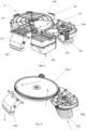
- FIG. 5 schematically shows, with arrows, a flow path of a dehumidifying airflow in the integrated washer-dryer according to the first embodiment of the present disclosure.
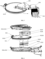
- FIG. 8 shows an exploded view of the moisture-absorbing rotary wheel assembly D11 in the integrated washer-dryer, according to the first embodiment of the present disclosure.
- the moisture-absorbing rotary wheel assembly D11 includes a wheel disc D111, an outer-periphery housing member D112, a center housing member D113, a power input member D114, an auxiliary rotation ring D115, a sealing member D116 of the rotary wheel, an outer-periphery damping member D117, and a center damping member D118.
- one sealing member D116 of the rotary wheel is disposed on the outer peripheral surface at the position where the outer-periphery upper clamp housing D112U and the outer-periphery lower clamp housing D112L are fixed to each other.
- the radial inner side of the sealing member D116 of the rotary wheel covers the position where the outer-periphery upper clamp housing D112U and the outer-periphery lower clamp housing D112L are fixed to each other.
- the moisture-absorbing rotary wheel assembly D11 further includes a deformable outer-periphery damping member D117 and a center damping member D118.
- the outer-periphery damping member D117 is disposed between the outer peripheral surface of the wheel disc D111 and the inner peripheral surface of the outer-periphery housing member D112 to form a buffer therebetween by using its own deformable property.
- the outer-periphery damping member D117 is glued onto the outer peripheral surface of the wheel disc D111.
- the center damping member D118 is disposed between the end segment of the center housing member D113 and the center region of the wheel disc D111 to form a buffer therebetween by using its own deformable property.
- the center damping member D118 is disposed between the end segment of the center lower clamp member D113L and the end surface of the center region of the wheel disc D111.
- the center damping member D118 may be also disposed between the end segment of the center upper clamp member D113U and the end surface of the center region of the wheel disc D111, or it is also possible to provide one center damping member D118 at each of the above two positions.
- the center damping member D118 is glued onto the end surface of the center region of the wheel disc D111.
- the outer-periphery damping member D117 and the center damping member D118 are made of, for example, foam.
- the outer-periphery damping member D117 and the center damping member D118 can be manufactured by using other elastically deformable materials.
- the drum produces vibration. This vibration may sometimes drive the complete machine to vibrate together, causing the moisture-absorbing rotary wheel assembly D11 to vibrate therewith as well.
- the outer-periphery damping member D117 and the center damping member D118 can axially and radially buffer this vibration to protect the typically brittle wheel disc D111 from damage.
- the dehumidifying and heating assembly housing D341 is configured to be a fan-shaped body having a fan-shaped cross section, and hence has a fan-shaped upper end surface wall D3411, a fan-shaped lower end surface wall D3412, a circumferential side wall D3413 extending circumferentially, and a radial side wall D3414 extending radially, and the circumferential side wall D3413 and the radial side wall D3414 connect the upper end surface wall D3411 and the lower end surface wall D3412 together.
- the fan-shaped body and the rotary wheel upper housing D12U of the rotary wheel housing D12 are configured in complementary shapes.
- the dehumidifying airflow inlet accounts for at least 80%, preferably 90%, of the area of the circumferential side wall D3413. Hence, the dehumidifying airflow can enter the dehumidifying and heating assembly D34 in the shortest path.
- the dehumidifying airflow inlet in the radial side wall such that the dehumidifying airflow can radially pass through the dehumidifying rotary wheel assembly more evenly, and, in particular, when a plurality of dehumidifying airflow inlets are arranged in the two radial side walls, or arranged in the two radial side walls and one circumferential side wall, the dehumidifying airflow can pass through the moisture-absorbing rotary wheel assembly more evenly within the cross-section range of the fan-shaped body, thereby improving the regeneration efficiency of the moisture-absorbing rotary wheel assembly.
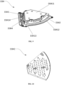
- FIG. 10 shows a perspective view of the mesh plate D342 in the dehumidifying and heating assembly D34 in the integrated washer-dryer, according to the first embodiment of the present disclosure from the front side.
- the mesh plate D342 has a shape matching the dehumidifying airflow outlet and can be fixed in the dehumidifying airflow outlet.
- a plurality of through holes is configured in the mesh plate D342, and these through holes are distributed in the mesh plate D342 as evenly as possible. In this case, these through holes are distributed in the mesh plate D342 in a snake-like form. Particularly advantageously, the apertures of these through holes gradually decrease in a flow direction of the dehumidifying airflow.
- the apertures of the through holes closer to the dehumidifying airflow inlet are larger, and the apertures of the through holes further away from the dehumidifying airflow inlet are smaller. That is, the apertures of these through holes are radially configured inward smaller and smaller. Hence, the evenness for the dehumidifying airflow to pass through the moisture-absorbing rotary wheel assembly can be further improved.
- FIG. 11 shows a perspective view of the dehumidifying and heating assembly D34 in the integrated washer-dryer according to the first embodiment of the present disclosure from the back side.
- the dehumidifying and heating member D343 is disposed in the flow direction of the dehumidifying airflow at the downstream side of the mesh plate D342, i.e., the back side of the mesh plate D342.
- the dehumidifying and heating member D343 is configured as a heating pipe spread in a plane in a snake-like form. It is also possible to contemplate constructing the dehumidifying and heating member D343 using a PTC heating body that consists of, for example, ceramic heating elements and aluminum pipes.
- the drying module assembly D may be pre-assembled into only one pre-assembled module before the assembling of the complete integrated washer-dryer.
- the pre-assembled module may include only one integrally formed lower module housing and a plurality of split upper housings.
- the lower module housing and the upper housings together form a plurality of chambers that are configured to accommodate various functional modules in the drying module assembly-for example, the moisture-absorbing rotary wheel assembly D11, the fan D23 for the moisture-absorbing passage, the fan D33 for the dehumidifying passage, the rotary wheel driving mechanism D13, the dehumidifying and heating assembly D34, and the dehumidifying and condensing assembly D35.
- This kind of integrated modular manufacturing greatly simplifies assembling and thus improves assembling efficiency on the one hand, and eliminates or shortens the corresponding connection pipeline on the other hand, thereby enabling a more compact structure of the drying module assembly.
- the other end of the second water outlet pipe P3 is connected to the water inlet of the cleaner holding box C.
- the other end of the third water outlet pipe P4 is connected to the water inlet of the air outlet pipeline L1.
- the space at the upper part of the drum R can be fully utilized such that the overall arrangement of the integrated washer-dryer 1 is very compact.
- Such an arrangement also facilitates the pipe circuit arrangement from the pipe assembly P to the water inlet of each assembly, which minimizes the overall length of the pipe circuit.
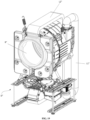
- the dehumidifying and condensing assembly D35, the cleaner holding box C, the water inlet of the air outlet pipeline L1, and the pipe assembly P are located at four corners of the integrated washer-dryer 1.
- the air outlet pipeline L1 is arranged at the rear right side of the drum R, and the water inlet of the air outlet pipeline L1 and the pipe assembly P are arranged together at the rear right corner of the integrated washer-dryer W such that the length of the pipe circuit from the third water outlet pipe P4 of the pipe assembly P to the water inlet of the air outlet pipeline L1 can be shortened.
- the water inlet pipe P1 and/or the first water outlet pipe P2 and/or the second water outlet pipe P3 and/or the third water outlet pipe P4 are/is provided with an electromagnetic valve to control the on/off and/or flow of a water pipe.
- the respective pipelines or water inlets may be connected by means of hoses. The use of the hoses can allow the pipe circuits to be flexibly arranged in gaps among the respective assemblies.
- FIG. 16 shows a perspective view of a longitudinal sectional view of an air outlet pipeline L1 provided with a filter screen self-cleaning device in the integrated washer-dryer, according to the present disclosure.
- the air outlet pipeline L1 is disposed behind and next to the drum R and extends from the bottom up. This extending way can reduce the overall height of the integrated washer-dryer 1 such that the integrated washer-dryer 1 can be conveniently placed below a tabletop.
- the air outlet pipeline L1 is connected, at the first end L11 thereof, to the air outlet of the drum R, and is connected, at the second end L12 thereof, to the drying module assembly D.
- the air outlet pipeline L1 includes a first half housing L13 and a second half housing L14 between which a cavity is defined.
- the second half housing L14 has an air inlet (not shown) for connecting to the air outlet of the drum R; and, at the end of the first half housing L13 facing the air inlet, the first half housing L13 preferably has a cambered inner surface for guiding the airflow entering the cavity.
- a cambered support plate L15 is provided at the second end L12 of the first half housing L13.
- the cambered support plate L15 is connected, at the first end thereof, to a top panel L131 of the first half housing L13, and extends, at the second end thereof, into the cavity.
- the cambered support plate L15 is advantageous for guiding the filtered airflow so as to avoid turbulence.
- All airflows entering the cavity from the air inlet at the first end L11 of the air outlet pipeline L1 first enter the non-clean space, sequentially pass through an air intake surface F11 and a cleaning surface F12 of the filter screen F1, then enter the clean space, and then are transferred to the drying module assembly via the air outlet (not shown) at the second end L12 of the air outlet pipeline L1. Due to this arrangement of the filter screen F1, inclusions filtered and left on the filter screen F1 mainly deposit on the air intake surface F11.
- a filter screen self-cleaning device F2 is disposed at the second end L12 of the air outlet pipeline L1.
- the filter screen self-cleaning device F2 sprays, at the non-clean space side, cleaner-containing tap water from one side of the air intake surface F11 of the filter screen F1 onto the filter screen so as to rinse off lint and other inclusions attached to the filter screen F1.
- the used tap water flows out of the water outlet (not shown) disposed in the first end L11 of the air outlet pipeline L1 and is discharged from the integrated washer-dryer, for example, via a discharge outlet disposed exclusively for liquid for self-cleaning use, or via a water draining port of the drum.
- the filter screen self-cleaning device may be also disposed on one side of the cleaning space so as to simultaneously or asynchronously rinse the cleaning surface of the filter screen F1 in order to clean the filter screen more thoroughly.
- the nozzle F22 connected to the water inlet pipe is disposed and configured on the top of the filter screen F1 to spray the tap water (which may contain a cleaner) onto the air intake surface F16 of the filter screen F1.
- a pressurization valve is disposed upstream of the water inlet pipe F21 to pressurize the tap water entering the filter screen self-cleaning device so as to rinse the filter screen F1 by using the pressurized tap water, which is advantageous to the improvement of the cleaning efficiency and the cost effectiveness.
- the water inlet pipe F21 may be fixed to the first half housing L13 in other forms, for example, by virtue of the support plate in the aforementioned flat plate form.
- the nozzle F22 includes an adapter F23 connected to the water inlet pipe F21 and an increasingly wider extending part F24 integrally formed with the adapter F23.
- the adapter F23 is fixedly connected to the water inlet pipe F21 by means of, for example, threaded connection, interference fit, adhesive, and other forms.
- the increasingly wider extending part F24 inclines at a certain angle with respect to the filter screen F1 and has a free end provided with an outlet that traverses a cavity of the air outlet pipeline L1 to cover the substantially entire width of the filter screen F1 (as shown in FIG. 3 ), thereby guaranteeing the cleaning coverage.
- an included angle between the increasingly wider extending part F24 and the filter screen F1 ranges from 0° to 45°, more preferably from 5° to 35°.
- An overlarge angle is averse to the flow of the tap water from the top of the filter screen F1 to the bottom of the filter screen F1, leading to reduced cleaning efficiency.
- the increasingly wider extending part is gradually reduced along its length (i.e., in its inclination direction) to form a flat opening at its free end, which facilitates water pressurization and increases the impact force to the filter screen F1, thereby increasing the cleaning efficiency.
- the air outlet pipeline L1 includes two layers of pipe walls; a chamber of a cooling passage L10 allowing the flow of cooling water is formed between the two layers of pipe walls; and the flow direction of a water flow A1 is shown by arrows and is opposite to the flow direction of an airflow A2, which is advantageous to cooling and liquification of the airflow.
- the cooling passage L10 guides the cooling water to flow to an outer wall of the air outlet pipeline L1 so as to cool and liquify an airflow flowing through therein, such that humid air discharged from the drum R has been pre-dehumidified before entering the drying module assembly D.
- a condensing mechanism K is disposed at the first end of the cooling passage L10 close to the drying module assembly D and includes a water inlet pipe K1 and a water spray nozzle K2 connected to the water inlet pipe K1.
- the water inlet pipe K1 is hermetically fixed to the first end of the cooling passage L10 by, for example, the combination of threaded fit and a sealant, and is connected to the tap water inlet pipe of the integrated washer-dryer W by, for example, an electromagnetic valve.
- the water inlet pipe K1 of the condensing mechanism 9 simultaneously forms the first water inlet for the air outlet pipeline L1 or the cooling passage L10.
- the water spray nozzle K2 is configured to spray the cooling water to the outer wall of the air outlet pipeline L1 so as to enhance the cooling effect of the cooling water on the outer wall.
- the water spray nozzle K2 includes an increasingly wider extending part, which is gradually reduced along its length to form a flat opening at its free end so as to increase a spray coverage and water pressure to further enhance the cooling effect on the outer wall of the air outlet pipeline.
- a plurality of water spray nozzles K2 may be disposed in the cooling passage L10.
- FIGs. 18 and 19 show perspective views of integrated washer-dryers according to a second embodiment and a third embodiment of the present disclosure. Unlike the first embodiment in which the drying module assembly D is arranged above the drum R, in the second embodiment, a drying module assembly D' is arranged behind a drum R'.
- an air outlet pipeline L1' for communicating the air outlet of the drum R' with the air inlet of the drying module assembly D', i.e., the air inlet of the moisture-absorbing passage, is arranged above the drum R' and between the drying module assembly D' and the drum R'; and an air inlet pipeline L2' for communicating the air inlet of the drum R' with the air outlet of the drying module assembly D', i.e., the air outlet of the moisture-absorbing passage, is arranged above the drum R'.
- a drying module assembly D" is arranged below a drum R".
- an air outlet pipeline L1" for communicating the air outlet of the drum R" with the air inlet of the drying module assembly D i.e., the air inlet of the moisture-absorbing passage
- an air inlet pipeline L2" for communicating the air inlet of the drum R" with the air outlet of the drying module assembly D i.e., the air outlet of the moisture-absorbing passage
- the arrangement in the first embodiment exhibits a particularly compact structure, a larger space for accommodating the functional assemblies in the drying module assembly D is reserved laterally above the drum R that is a horizontally arranged cylinder, and the arrangement of the drying module assembly D above the drum further facilitates assembling and maintenance.
- the drying module assembly described above may be also applied to the fields of clothes dryers, dehumidifiers, dishwashers and others requiring dehumidification.
Landscapes
- Engineering & Computer Science (AREA)
- Textile Engineering (AREA)
- Detail Structures Of Washing Machines And Dryers (AREA)
- Drying Of Gases (AREA)
- Drying Of Solid Materials (AREA)
- Control Of Washing Machine And Dryer (AREA)
- Chemical & Material Sciences (AREA)
- Main Body Construction Of Washing Machines And Laundry Dryers (AREA)
- Analytical Chemistry (AREA)
- General Chemical & Material Sciences (AREA)
- Oil, Petroleum & Natural Gas (AREA)
- Chemical Kinetics & Catalysis (AREA)
Applications Claiming Priority (3)
| Application Number | Priority Date | Filing Date | Title |
|---|---|---|---|
| CN202111023112.5A CN113981647A (zh) | 2021-09-01 | 2021-09-01 | 一种洗烘一体机 |
| CN202111450553 | 2021-11-30 | ||
| PCT/CN2022/116142 WO2023030375A1 (fr) | 2021-09-01 | 2022-08-31 | Lave-linge séchant intégré |
Publications (2)
| Publication Number | Publication Date |
|---|---|
| EP4394120A1 true EP4394120A1 (fr) | 2024-07-03 |
| EP4394120A4 EP4394120A4 (fr) | 2025-08-06 |
Family
ID=83438804
Family Applications (5)
| Application Number | Title | Priority Date | Filing Date |
|---|---|---|---|
| EP22863510.8A Pending EP4394120A4 (fr) | 2021-09-01 | 2022-08-31 | Lave-linge séchant intégré |
| EP22863529.8A Pending EP4386130A4 (fr) | 2021-09-01 | 2022-08-31 | Appareil de traitement de linge |
| EP22863556.1A Pending EP4397804A4 (fr) | 2021-09-01 | 2022-08-31 | Appareil de séchage et machine intégrée de lavage et de séchage |
| EP22777000.5A Pending EP4396403A1 (fr) | 2021-09-01 | 2022-09-01 | Système de séchage et lave-linges l'utilisant |
| EP23858522.8A Pending EP4582611A1 (fr) | 2021-09-01 | 2023-01-17 | Équipement de traitement de vêtements |
Family Applications After (4)
| Application Number | Title | Priority Date | Filing Date |
|---|---|---|---|
| EP22863529.8A Pending EP4386130A4 (fr) | 2021-09-01 | 2022-08-31 | Appareil de traitement de linge |
| EP22863556.1A Pending EP4397804A4 (fr) | 2021-09-01 | 2022-08-31 | Appareil de séchage et machine intégrée de lavage et de séchage |
| EP22777000.5A Pending EP4396403A1 (fr) | 2021-09-01 | 2022-09-01 | Système de séchage et lave-linges l'utilisant |
| EP23858522.8A Pending EP4582611A1 (fr) | 2021-09-01 | 2023-01-17 | Équipement de traitement de vêtements |
Country Status (9)
| Country | Link |
|---|---|
| US (5) | US20240392494A1 (fr) |
| EP (5) | EP4394120A4 (fr) |
| JP (6) | JP2024532523A (fr) |
| KR (6) | KR20240035642A (fr) |
| CN (16) | CN115726133B (fr) |
| AU (7) | AU2022340524B2 (fr) |
| CA (3) | CA3230580A1 (fr) |
| TW (12) | TW202447025A (fr) |
| WO (6) | WO2023030375A1 (fr) |
Families Citing this family (16)
| Publication number | Priority date | Publication date | Assignee | Title |
|---|---|---|---|---|
| WO2023030375A1 (fr) * | 2021-09-01 | 2023-03-09 | 深圳洛克创新科技有限公司 | Lave-linge séchant intégré |
| CN113981647A (zh) * | 2021-09-01 | 2022-01-28 | 北京石头世纪科技股份有限公司 | 一种洗烘一体机 |
| AU2023335613A1 (en) * | 2022-08-31 | 2025-04-10 | Shenzhen Roborock Innovation Technology Co., Ltd. | Tableware treatment device |
| WO2024046358A1 (fr) * | 2022-08-31 | 2024-03-07 | 深圳洛克创新科技有限公司 | Module de séchage et machine intégrée de lavage-séchage |
| CN118360769A (zh) * | 2023-01-17 | 2024-07-19 | 深圳洛克创新科技有限公司 | 一种过滤器清洁装置、衣物处理设备及其控制方法 |
| CN118932678A (zh) * | 2023-05-10 | 2024-11-12 | 青岛海尔洗衣机有限公司 | 一种衣物处理设备 |
| WO2025045095A1 (fr) * | 2023-08-31 | 2025-03-06 | 南京石头创新科技有限公司 | Appareil de traitement de linge |
| CN119571591A (zh) * | 2023-08-31 | 2025-03-07 | 南京石头创新科技有限公司 | 衣物处理设备 |
| CN119571573A (zh) * | 2023-08-31 | 2025-03-07 | 南京石头创新科技有限公司 | 供水控制方法及装置、衣物处理设备和存储介质 |
| WO2025067309A1 (fr) * | 2023-09-26 | 2025-04-03 | 南京石头创新科技有限公司 | Composant d'absorption d'humidité, module de séchage et dispositif de traitement de vêtements |
| WO2025232776A1 (fr) * | 2024-05-07 | 2025-11-13 | 南京石头创新科技有限公司 | Module de séchage et appareil de traitement de linge |
| CN223373466U (zh) * | 2024-09-04 | 2025-09-23 | 南京石头创新科技有限公司 | 一种冷凝装置、烘干装置及洗涤设备 |
| CN121719064A (zh) * | 2024-09-14 | 2026-03-24 | 青岛海尔洗涤电器有限公司 | 线屑清理装置、清理方法及衣物处理设备 |
| CN118846697B (zh) * | 2024-09-24 | 2025-01-28 | 苏能(锡林郭勒)发电有限公司 | 一种褐煤机组烟气净化系统 |
| CN119265889B (zh) * | 2024-12-06 | 2026-03-24 | 珠海格力电器股份有限公司 | 用于洗衣机的烘干设备 |
| CN121363832B (zh) * | 2025-12-18 | 2026-03-20 | 江苏永盛生物科技有限公司 | 一种猪血球蛋白粉生产用冷却装置 |
Family Cites Families (113)
| Publication number | Priority date | Publication date | Assignee | Title |
|---|---|---|---|---|
| JPS58118796A (ja) * | 1982-01-06 | 1983-07-14 | 株式会社日立製作所 | 衣類乾燥機 |
| DE3626887A1 (de) * | 1986-08-08 | 1988-02-11 | Miele & Cie | Waeschebehandlungs- und spuelgeraet, herd o. dgl., mit einer entfeuchtungseinrichtung |
| JP2753291B2 (ja) * | 1988-12-14 | 1998-05-18 | 株式会社日立製作所 | 衣類乾燥機用水冷式熱交換器 |
| JP2806542B2 (ja) * | 1989-02-17 | 1998-09-30 | 株式会社日立製作所 | 衣類乾燥機 |
| JPH0510669A (ja) * | 1991-07-04 | 1993-01-19 | Matsushita Electric Ind Co Ltd | 衣類乾燥機 |
| JP3043126B2 (ja) * | 1991-08-28 | 2000-05-22 | 三洋電機株式会社 | 衣類乾燥機 |
| CN1139163A (zh) * | 1995-06-29 | 1997-01-01 | 上海家用空调器总厂 | 热泵加热制冷去湿内循环排湿干衣机 |
| JP2000051576A (ja) * | 1998-08-04 | 2000-02-22 | Sharp Corp | 洗濯機 |
| JP2000225288A (ja) * | 1999-02-04 | 2000-08-15 | Matsushita Electric Ind Co Ltd | 洗濯乾燥機 |
| JP2002340372A (ja) * | 2001-05-17 | 2002-11-27 | Matsushita Electric Ind Co Ltd | 除湿デバイス |
| JP4196075B2 (ja) * | 2003-04-11 | 2008-12-17 | パナソニック株式会社 | 洗濯乾燥機 |
| JP3650104B2 (ja) * | 2003-05-21 | 2005-05-18 | シャープ株式会社 | 衣類乾燥機 |
| JP2005021601A (ja) * | 2003-07-03 | 2005-01-27 | Toshiba Corp | 洗濯乾燥機 |
| KR20050012100A (ko) * | 2003-07-24 | 2005-01-31 | 삼성전자주식회사 | 세탁기용 건조장치 및 이를 포함한 세탁기 |
| WO2005012624A1 (fr) * | 2003-07-30 | 2005-02-10 | John Edward Gough | Sechoir |
| ZA200602582B (en) * | 2003-09-29 | 2008-11-26 | Self Propelled Res And Dev Spe | Heat pump clothes dryer |
| JP2006020754A (ja) * | 2004-07-07 | 2006-01-26 | Matsushita Electric Ind Co Ltd | 洗濯乾燥機 |
| KR100598233B1 (ko) * | 2004-10-08 | 2006-07-07 | 엘지전자 주식회사 | 건조 겸용 세탁기 |
| KR101235193B1 (ko) * | 2005-06-13 | 2013-02-20 | 삼성전자주식회사 | 세탁기 및 그 제어방법 |
| JP2007075241A (ja) | 2005-09-13 | 2007-03-29 | Matsushita Electric Ind Co Ltd | 洗濯乾燥機 |
| JP4676291B2 (ja) * | 2005-09-22 | 2011-04-27 | パナソニック株式会社 | 衣類乾燥装置 |
| JP3920299B2 (ja) * | 2005-09-22 | 2007-05-30 | 松下電器産業株式会社 | 衣類乾燥装置 |
| JP2007098261A (ja) * | 2005-10-04 | 2007-04-19 | Matsushita Electric Ind Co Ltd | 除湿機 |
| JP4247637B2 (ja) * | 2006-02-24 | 2009-04-02 | Toto株式会社 | 浴室乾燥機 |
| JP2007301010A (ja) * | 2006-05-09 | 2007-11-22 | Sharp Corp | 洗濯乾燥機 |
| JP2007306960A (ja) * | 2006-05-16 | 2007-11-29 | Matsushita Electric Ind Co Ltd | 衣類乾燥装置 |
| JP2008029654A (ja) | 2006-07-31 | 2008-02-14 | Sharp Corp | 洗濯乾燥機 |
| JP2008035958A (ja) * | 2006-08-02 | 2008-02-21 | Sharp Corp | 洗濯乾燥機 |
| JP2008055077A (ja) * | 2006-09-04 | 2008-03-13 | Matsushita Electric Ind Co Ltd | 洗濯乾燥機 |
| JP4910607B2 (ja) * | 2006-10-02 | 2012-04-04 | パナソニック株式会社 | 除湿装置 |
| JP2008259665A (ja) * | 2007-04-12 | 2008-10-30 | Sharp Corp | ドラム式洗濯乾燥機 |
| KR20090001073A (ko) * | 2007-06-29 | 2009-01-08 | 엘지전자 주식회사 | 복합의류처리장치 |
| JP4423323B2 (ja) * | 2007-10-02 | 2010-03-03 | 日立アプライアンス株式会社 | ドラム式乾燥機及びドラム式洗濯乾燥機 |
| JP5243005B2 (ja) * | 2007-11-30 | 2013-07-24 | 象印マホービン株式会社 | 除湿機 |
| JP4559502B2 (ja) * | 2008-03-14 | 2010-10-06 | 三菱電機株式会社 | 除湿機 |
| JP2009240937A (ja) | 2008-03-31 | 2009-10-22 | Panasonic Corp | 除湿装置 |
| JP4972612B2 (ja) * | 2008-05-30 | 2012-07-11 | 日立アプライアンス株式会社 | 洗濯機、および洗濯乾燥機 |
| DE102008054548A1 (de) * | 2008-12-11 | 2010-06-17 | BSH Bosch und Siemens Hausgeräte GmbH | Trockner mit Umluftanteil sowie Verfahren zu seinem Betrieb |
| JP2010167178A (ja) * | 2009-01-26 | 2010-08-05 | Mitsubishi Electric Corp | 洗濯乾燥機 |
| EP2246470B1 (fr) * | 2009-04-28 | 2014-06-04 | Candy S.p.A. | Machine à laver séchante |
| JP5289171B2 (ja) * | 2009-05-01 | 2013-09-11 | 三菱電機株式会社 | 除湿乾燥機 |
| KR101663610B1 (ko) * | 2009-05-28 | 2016-10-07 | 엘지전자 주식회사 | 세탁장치 |
| JP5345469B2 (ja) * | 2009-08-11 | 2013-11-20 | 象印マホービン株式会社 | 除湿機及びその運転制御方法 |
| JP4698750B2 (ja) * | 2009-09-24 | 2011-06-08 | シャープ株式会社 | 洗濯機及び乾燥機 |
| JP5068295B2 (ja) * | 2009-09-24 | 2012-11-07 | シャープ株式会社 | 乾燥機 |
| EP2366827B1 (fr) * | 2010-03-18 | 2013-01-02 | Askoll Holding S.r.l. | Ensemble ventilateur et moteur pour un sèche-linge à condensation et un sèche-linge à condensation ayant cet ensemble |
| KR101736435B1 (ko) * | 2010-06-23 | 2017-05-16 | 삼성전자주식회사 | 건조덕트를 구비하는 가전제품 |
| JP2012029783A (ja) * | 2010-07-29 | 2012-02-16 | Sanyo Electric Co Ltd | 乾燥機 |
| US8572865B2 (en) * | 2010-10-29 | 2013-11-05 | General Electric Company | Apparatus and method for using a hybrid dryer tub for airflow improvement |
| PL2471994T3 (pl) * | 2011-01-04 | 2019-12-31 | Electrolux Home Products Corporation N.V. | Urządzenie do suszenia materiałów pranych |
| JP2012161355A (ja) * | 2011-02-03 | 2012-08-30 | Toshiba Corp | 衣類乾燥機 |
| CN202116896U (zh) * | 2011-03-31 | 2012-01-18 | 无锡小天鹅股份有限公司 | 洗烘一体机的烘干冷凝装置 |
| EP2695986B1 (fr) * | 2011-04-05 | 2016-07-20 | LG Electronics Inc. | Machine à laver le linge et procédé de nettoyage de filtre à charpie de machine à laver le linge |
| CN103228999A (zh) * | 2011-05-26 | 2013-07-31 | 7734123加拿大有限公司 | 用于标准和防爆除湿系统的微波再活化系统 |
| CN102206916B (zh) * | 2011-06-23 | 2016-08-31 | 青岛海尔洗衣机有限公司 | 一种用于滚筒干衣的热泵烘干系统及控制方法 |
| CN102286872B (zh) * | 2011-07-12 | 2016-11-16 | 青岛海尔滚筒洗衣机有限公司 | 一种带热泵烘干和除湿功能的洗衣干衣机 |
| ES2443874T3 (es) * | 2011-07-21 | 2014-02-20 | Whirlpool Corporation | Método para controlar una secadora de ropa y secadora de ropa que utilice tal método |
| AU2013244150B2 (en) * | 2012-04-06 | 2016-02-11 | Lg Electronics Inc. | Laundry treating machine |
| US9140396B2 (en) * | 2013-03-15 | 2015-09-22 | Water-Gen Ltd. | Dehumidification apparatus |
| KR101579465B1 (ko) * | 2013-07-19 | 2015-12-23 | 엘지전자 주식회사 | 건조기 |
| JP6373020B2 (ja) * | 2014-03-06 | 2018-08-15 | シャープ株式会社 | 乾燥機 |
| KR102188109B1 (ko) * | 2014-05-30 | 2020-12-07 | 삼성전자주식회사 | 식기세척기 |
| CN105297372B (zh) * | 2014-07-31 | 2019-02-19 | 青岛海尔洗衣机有限公司 | 一种衣物烘干系统及烘干方法、洗衣干衣一体机、干衣机 |
| CN204491256U (zh) * | 2014-12-24 | 2015-07-22 | 珠海格力电器股份有限公司 | 干衣机及其调湿装置 |
| KR102053323B1 (ko) * | 2015-07-31 | 2019-12-06 | 주식회사 엘지화학 | 흡습 부재가 구비된 세탁기 |
| CN106498683A (zh) * | 2015-09-07 | 2017-03-15 | 青岛海尔洗衣机有限公司 | 一种干衣机及控制方法 |
| CN106917221B (zh) * | 2015-10-26 | 2019-12-27 | 东芝生活电器株式会社 | 衣物烘干机 |
| JP6619997B2 (ja) * | 2015-11-25 | 2019-12-11 | 日立グローバルライフソリューションズ株式会社 | 洗濯乾燥機 |
| CN106868831A (zh) * | 2015-12-11 | 2017-06-20 | 上海日立电器有限公司 | 热泵型干衣机及其工作方法 |
| CN105463812B (zh) * | 2015-12-30 | 2019-03-01 | Tcl家用电器(合肥)有限公司 | 洗烘一体机 |
| KR102585024B1 (ko) * | 2016-01-05 | 2023-10-05 | 엘지전자 주식회사 | 히트펌프 모듈을 구비하는 의류처리장치 |
| CN107447472B (zh) * | 2016-05-31 | 2019-09-17 | 无锡小天鹅电器有限公司 | 热泵安装盒及热泵干衣机或热泵洗干一体机 |
| KR20180014615A (ko) * | 2016-08-01 | 2018-02-09 | 엘지전자 주식회사 | 의류처리장치 |
| TWI769178B (zh) * | 2016-09-28 | 2022-07-01 | 日商松下知識產權經營股份有限公司 | 除濕裝置 |
| CN108004733B (zh) * | 2016-10-31 | 2020-04-17 | 众智光电科技股份有限公司 | 烘衣机 |
| JP2018071901A (ja) * | 2016-10-31 | 2018-05-10 | 大阪瓦斯株式会社 | 乾燥システムおよびその運転方法 |
| KR102613562B1 (ko) * | 2016-12-29 | 2023-12-14 | 엘지전자 주식회사 | 듀얼 타입 건조기 |
| WO2018196766A1 (fr) * | 2017-04-25 | 2018-11-01 | 青岛海尔洗衣机有限公司 | Système de séchage de machine à laver, et machine à laver |
| KR102358922B1 (ko) * | 2017-06-22 | 2022-02-07 | 주식회사 경동나비엔 | 건조장치 및 건조방법 |
| CN109402988B (zh) * | 2017-08-16 | 2022-02-22 | 青岛海尔洗涤电器有限公司 | 烘干系统控制方法及衣物处理装置 |
| CN107663761B (zh) * | 2017-08-29 | 2019-12-10 | 珠海格力电器股份有限公司 | 衣物烘干判断方法和装置 |
| CN107558128B (zh) * | 2017-09-11 | 2023-06-30 | 珠海格力电器股份有限公司 | 衣物干燥设备及其控制方法 |
| CN207159639U (zh) * | 2017-09-13 | 2018-03-30 | 赵正华 | 采用热泵加热和冷凝集水功能的干衣机 |
| JP6948235B2 (ja) * | 2017-11-28 | 2021-10-13 | 東芝ライフスタイル株式会社 | 衣類乾燥機 |
| CN110055730B (zh) * | 2018-01-18 | 2022-01-04 | 重庆海尔滚筒洗衣机有限公司 | 一种热泵干衣机及控制方法 |
| CN110106681B (zh) * | 2018-02-01 | 2024-09-27 | 青岛海尔洗护电器有限公司 | 一种风道转换装置及衣物处理装置 |
| JP2019150413A (ja) * | 2018-03-06 | 2019-09-12 | 日立グローバルライフソリューションズ株式会社 | 洗濯乾燥機 |
| JP2019187613A (ja) * | 2018-04-20 | 2019-10-31 | 東芝ライフスタイル株式会社 | 衣類乾燥機 |
| KR20190128469A (ko) * | 2018-05-08 | 2019-11-18 | 엘지전자 주식회사 | 의류 처리 장치 |
| CN111101351B (zh) * | 2018-10-26 | 2022-08-26 | 无锡小天鹅电器有限公司 | 烘干系统和衣物处理装置 |
| EP3696313A1 (fr) * | 2019-02-15 | 2020-08-19 | Miele & Cie. KG | Appareil de traitement du linge, de préférence sèche-linge |
| CN109629206B (zh) * | 2019-02-18 | 2023-11-28 | 珠海格力电器股份有限公司 | 烘干设备及该烘干设备的运行方法 |
| KR102882012B1 (ko) * | 2019-03-21 | 2025-11-11 | 삼성전자주식회사 | 세탁기 및 그 제어 방법 |
| JP2021121262A (ja) * | 2020-01-31 | 2021-08-26 | 東芝ライフスタイル株式会社 | 衣類乾燥機 |
| CN113389024A (zh) * | 2020-03-12 | 2021-09-14 | 博西华电器(江苏)有限公司 | 衣物处理装置 |
| CN111235844B (zh) * | 2020-03-20 | 2025-06-20 | 珠海格力电器股份有限公司 | 干衣系统、干衣机及洗干衣一体机 |
| CN111560642A (zh) * | 2020-05-18 | 2020-08-21 | 钟国财 | 一种汽车皮带轮电镀设备 |
| CN212199700U (zh) * | 2020-05-20 | 2020-12-22 | 山东大成洗涤机械有限公司 | 一种洗烘一体机 |
| CN111926524B (zh) * | 2020-08-24 | 2024-08-27 | 长虹美菱股份有限公司 | 一种洗干一体机 |
| CN213896424U (zh) * | 2020-09-22 | 2021-08-06 | 云米互联科技(广东)有限公司 | 水气分离的换热组件及衣物烘干装置 |
| CN113605036B (zh) * | 2020-10-26 | 2024-09-10 | 松下家电(中国)有限公司 | 衣物处理设备的护理控制方法 |
| CN112709040A (zh) * | 2020-12-22 | 2021-04-27 | 珠海格力电器股份有限公司 | 一种多桶洗衣干衣一体机及其控制方法 |
| CN112779718B (zh) * | 2020-12-29 | 2022-03-01 | 珠海格力电器股份有限公司 | 一种洗涤装置及控制方法 |
| CN113418242A (zh) * | 2021-06-03 | 2021-09-21 | 重庆海尔空调器有限公司 | 无水加湿装置、空调器 |
| CN113584800B (zh) * | 2021-08-02 | 2022-09-27 | 珠海格力电器股份有限公司 | 一种内衣烘干方法及洗烘一体设备 |
| WO2023030375A1 (fr) * | 2021-09-01 | 2023-03-09 | 深圳洛克创新科技有限公司 | Lave-linge séchant intégré |
| CN113981647A (zh) * | 2021-09-01 | 2022-01-28 | 北京石头世纪科技股份有限公司 | 一种洗烘一体机 |
| CN216585700U (zh) * | 2021-09-01 | 2022-05-24 | 北京石头世纪科技股份有限公司 | 一种洗烘一体机 |
| CN114136000B (zh) * | 2021-11-30 | 2022-12-20 | 珠海格力电器股份有限公司 | 一种清除组件、新风系统、空调器及清除方法 |
| CN114293357B (zh) * | 2021-12-01 | 2024-02-20 | 广东美的白色家电技术创新中心有限公司 | 衣物处理设备及其控制方法、装置和存储介质 |
| CN114318814B (zh) * | 2021-12-07 | 2022-11-25 | 珠海格力电器股份有限公司 | 烘干风道、洗干一体机及烘干风道的控制方法 |
| CN216769611U (zh) * | 2022-01-05 | 2022-06-17 | 宁波奥克斯电气股份有限公司 | 一种转轮结构、无水加湿模块及空调器 |
| CN114606745A (zh) * | 2022-03-09 | 2022-06-10 | 创维电器股份有限公司 | 一种干衣机的判干方法 |
-
2022
- 2022-08-31 WO PCT/CN2022/116142 patent/WO2023030375A1/fr not_active Ceased
- 2022-08-31 US US18/688,716 patent/US20240392494A1/en active Pending
- 2022-08-31 CN CN202211059234.4A patent/CN115726133B/zh active Active
- 2022-08-31 TW TW113129047A patent/TW202447025A/zh unknown
- 2022-08-31 EP EP22863510.8A patent/EP4394120A4/fr active Pending
- 2022-08-31 CN CN202222307661.1U patent/CN218521473U/zh active Active
- 2022-08-31 JP JP2024514365A patent/JP2024532523A/ja active Pending
- 2022-08-31 AU AU2022340524A patent/AU2022340524B2/en active Active
- 2022-08-31 CN CN202280057397.0A patent/CN117940629A/zh active Pending
- 2022-08-31 EP EP22863529.8A patent/EP4386130A4/fr active Pending
- 2022-08-31 JP JP2024514384A patent/JP2024530799A/ja active Pending
- 2022-08-31 AU AU2022338834A patent/AU2022338834B2/en active Active
- 2022-08-31 JP JP2024514385A patent/JP7769785B2/ja active Active
- 2022-08-31 TW TW111133042A patent/TWI854293B/zh active
- 2022-08-31 KR KR1020247007632A patent/KR20240035642A/ko active Pending
- 2022-08-31 TW TW113129048A patent/TWI889478B/zh active
- 2022-08-31 WO PCT/CN2022/116242 patent/WO2023030394A1/fr not_active Ceased
- 2022-08-31 US US18/688,711 patent/US20250003137A1/en active Pending
- 2022-08-31 TW TW113129046A patent/TWI889477B/zh active
- 2022-08-31 KR KR1020247010814A patent/KR20240046831A/ko active Pending
- 2022-08-31 CA CA3230580A patent/CA3230580A1/fr active Pending
- 2022-08-31 EP EP22863556.1A patent/EP4397804A4/fr active Pending
- 2022-08-31 WO PCT/CN2022/116387 patent/WO2023030421A1/fr not_active Ceased
- 2022-08-31 CA CA3230573A patent/CA3230573A1/fr active Pending
- 2022-08-31 CN CN202280059358.4A patent/CN118019887A/zh active Pending
- 2022-08-31 CA CA3230592A patent/CA3230592A1/fr active Pending
- 2022-08-31 CN CN202280059311.8A patent/CN117999387A/zh active Pending
- 2022-08-31 US US18/688,706 patent/US20240384455A1/en active Pending
- 2022-08-31 TW TW113129049A patent/TW202447027A/zh unknown
- 2022-08-31 AU AU2022336912A patent/AU2022336912B2/en active Active
- 2022-08-31 KR KR1020247007710A patent/KR20240038113A/ko active Pending
- 2022-09-01 CN CN202280058173.1A patent/CN117881840A/zh active Pending
- 2022-09-01 AU AU2022339127A patent/AU2022339127B2/en active Active
- 2022-09-01 US US18/688,586 patent/US20240368820A1/en active Pending
- 2022-09-01 WO PCT/IB2022/058200 patent/WO2023031837A1/fr not_active Ceased
- 2022-09-01 JP JP2024514367A patent/JP7832308B2/ja active Active
- 2022-09-01 KR KR1020247010839A patent/KR20240048569A/ko active Pending
- 2022-09-01 EP EP22777000.5A patent/EP4396403A1/fr active Pending
-
2023
- 2023-01-17 WO PCT/CN2023/072662 patent/WO2024045479A1/fr not_active Ceased
- 2023-01-17 US US19/108,118 patent/US20250369171A1/en active Pending
- 2023-01-17 CN CN202320207530.8U patent/CN220486085U/zh active Active
- 2023-01-17 AU AU2023332258A patent/AU2023332258A1/en active Pending
- 2023-01-17 CN CN202320207551.XU patent/CN220183633U/zh active Active
- 2023-01-17 CN CN202320207500.7U patent/CN220827603U/zh active Active
- 2023-01-17 CN CN202310090596.8A patent/CN117646320A/zh active Pending
- 2023-01-17 KR KR1020257010410A patent/KR20250053189A/ko active Pending
- 2023-01-17 CN CN202320180495.5U patent/CN220486100U/zh active Active
- 2023-01-17 JP JP2025513031A patent/JP2025527870A/ja active Pending
- 2023-01-17 CN CN202320159542.8U patent/CN218812690U/zh active Active
- 2023-01-17 WO PCT/CN2023/072661 patent/WO2024045478A1/fr not_active Ceased
- 2023-01-17 KR KR1020257010534A patent/KR20250055612A/ko active Pending
- 2023-01-17 CN CN202320180503.6U patent/CN220827602U/zh active Active
- 2023-01-17 CN CN202320169591.XU patent/CN220846753U/zh active Active
- 2023-01-17 EP EP23858522.8A patent/EP4582611A1/fr active Pending
- 2023-01-17 CN CN202320177042.7U patent/CN220486084U/zh active Active
- 2023-01-17 CN CN202310110896.8A patent/CN117626611A/zh active Pending
- 2023-08-24 AU AU2023335349A patent/AU2023335349A1/en active Pending
- 2023-08-28 TW TW112132359A patent/TWI868879B/zh active
- 2023-08-28 TW TW112132302A patent/TWI844459B/zh active
- 2023-08-28 TW TW113146647A patent/TWI900355B/zh active
- 2023-08-29 TW TW112132506A patent/TWI852747B/zh active
- 2023-08-29 TW TW112132636A patent/TWI879052B/zh active
- 2023-08-29 TW TW112132644A patent/TWI909199B/zh active
- 2023-08-30 TW TW112132719A patent/TW202421884A/zh unknown
-
2025
- 2025-08-22 JP JP2025139191A patent/JP2025166249A/ja active Pending
-
2026
- 2026-02-16 AU AU2026201136A patent/AU2026201136A1/en active Pending
Also Published As
Similar Documents
| Publication | Publication Date | Title |
|---|---|---|
| AU2022336912B2 (en) | Integrated washer dryer | |
| CN218842642U (zh) | 洗烘一体机 | |
| EP4442884A1 (fr) | Dispositif de traitement de vêtements | |
| TWI901998B (zh) | 衣物處理設備及其控制方法 | |
| RU2857893C1 (ru) | Стиральная машина с функцией сушки и модуль сушки | |
| RU2840401C2 (ru) | Стиральная машина с функцией сушки | |
| JP2025527817A5 (fr) | ||
| RU2829711C2 (ru) | Стиральный агрегат | |
| RU2843157C2 (ru) | Объединенная стирально-сушильная машина | |
| RU2852032C2 (ru) | Стиральный агрегат и способ эксплуатации стирального агрегата | |
| RU2860535C2 (ru) | Стирально-сушильная машина | |
| RU2850256C2 (ru) | Устройство обработки одежды | |
| RU2836453C2 (ru) | Устройство обработки одежды | |
| TWI913577B (zh) | 衣物處理設備 | |
| JP2025529966A (ja) | 洗濯乾燥一体型洗濯機 |
Legal Events
| Date | Code | Title | Description |
|---|---|---|---|
| STAA | Information on the status of an ep patent application or granted ep patent |
Free format text: STATUS: THE INTERNATIONAL PUBLICATION HAS BEEN MADE |
|
| PUAI | Public reference made under article 153(3) epc to a published international application that has entered the european phase |
Free format text: ORIGINAL CODE: 0009012 |
|
| STAA | Information on the status of an ep patent application or granted ep patent |
Free format text: STATUS: REQUEST FOR EXAMINATION WAS MADE |
|
| 17P | Request for examination filed |
Effective date: 20240326 |
|
| AK | Designated contracting states |
Kind code of ref document: A1 Designated state(s): AL AT BE BG CH CY CZ DE DK EE ES FI FR GB GR HR HU IE IS IT LI LT LU LV MC MK MT NL NO PL PT RO RS SE SI SK SM TR |
|
| RAP1 | Party data changed (applicant data changed or rights of an application transferred) |
Owner name: NANJING ROBOROCK INNOVATION TECHNOLOGY CO., LTD. |
|
| DAV | Request for validation of the european patent (deleted) | ||
| DAX | Request for extension of the european patent (deleted) | ||
| A4 | Supplementary search report drawn up and despatched |
Effective date: 20250703 |
|
| RIC1 | Information provided on ipc code assigned before grant |
Ipc: D06F 58/24 20060101AFI20250627BHEP Ipc: D06F 58/02 20060101ALI20250627BHEP Ipc: D06F 25/00 20060101ALI20250627BHEP Ipc: D06F 29/00 20060101ALI20250627BHEP Ipc: D06F 58/20 20060101ALN20250627BHEP Ipc: D06F 58/22 20060101ALN20250627BHEP Ipc: D06F 58/26 20060101ALN20250627BHEP Ipc: D06F 58/45 20200101ALN20250627BHEP |