EP4394143A1 - Ensemble échafaudage - Google Patents
Ensemble échafaudage Download PDFInfo
- Publication number
- EP4394143A1 EP4394143A1 EP23150017.4A EP23150017A EP4394143A1 EP 4394143 A1 EP4394143 A1 EP 4394143A1 EP 23150017 A EP23150017 A EP 23150017A EP 4394143 A1 EP4394143 A1 EP 4394143A1
- Authority
- EP
- European Patent Office
- Prior art keywords
- cover
- scaffolding
- roller device
- configuration
- core
- Prior art date
- Legal status (The legal status is an assumption and is not a legal conclusion. Google has not performed a legal analysis and makes no representation as to the accuracy of the status listed.)
- Withdrawn
Links
Images



Classifications
-
- E—FIXED CONSTRUCTIONS
- E04—BUILDING
- E04G—SCAFFOLDING; FORMS; SHUTTERING; BUILDING IMPLEMENTS OR AIDS, OR THEIR USE; HANDLING BUILDING MATERIALS ON THE SITE; REPAIRING, BREAKING-UP OR OTHER WORK ON EXISTING BUILDINGS
- E04G5/00—Component parts or accessories for scaffolds
- E04G5/12—Canopies
-
- E—FIXED CONSTRUCTIONS
- E04—BUILDING
- E04G—SCAFFOLDING; FORMS; SHUTTERING; BUILDING IMPLEMENTS OR AIDS, OR THEIR USE; HANDLING BUILDING MATERIALS ON THE SITE; REPAIRING, BREAKING-UP OR OTHER WORK ON EXISTING BUILDINGS
- E04G21/00—Preparing, conveying, or working-up building materials or building elements in situ; Other devices or measures for constructional work
- E04G21/24—Safety or protective measures preventing damage to building parts or finishing work during construction
- E04G21/28—Safety or protective measures preventing damage to building parts or finishing work during construction against unfavourable weather influence
-
- E—FIXED CONSTRUCTIONS
- E04—BUILDING
- E04G—SCAFFOLDING; FORMS; SHUTTERING; BUILDING IMPLEMENTS OR AIDS, OR THEIR USE; HANDLING BUILDING MATERIALS ON THE SITE; REPAIRING, BREAKING-UP OR OTHER WORK ON EXISTING BUILDINGS
- E04G5/00—Component parts or accessories for scaffolds
- E04G5/12—Canopies
- E04G2005/125—Roof for scaffolds, e.g. extending to the adjacent building
-
- E—FIXED CONSTRUCTIONS
- E04—BUILDING
- E04G—SCAFFOLDING; FORMS; SHUTTERING; BUILDING IMPLEMENTS OR AIDS, OR THEIR USE; HANDLING BUILDING MATERIALS ON THE SITE; REPAIRING, BREAKING-UP OR OTHER WORK ON EXISTING BUILDINGS
- E04G21/00—Preparing, conveying, or working-up building materials or building elements in situ; Other devices or measures for constructional work
- E04G21/24—Safety or protective measures preventing damage to building parts or finishing work during construction
- E04G2021/248—Tarpaulins specially adapted therefor
Definitions
- a cover may hinder access to the work space, e.g. for transporting tools and/or supplies, so that it should be removable. Also, e.g. in view of wind strengths a cover on a scaffolding may be have to be removed for protection of one or more of the construction, the scaffolding, the cover, and/or for prevention of noise due to flapping material.
- the core may be a rotatable axle and/or may be a hollow core rotatably mounted about an axle, and/or wherein the core comprises flanges for guiding rolling-up of cover material
- the roller device may comprise a housing at least partly enclosing at least part of the rollable portion in the rolled-up configuration.
- the roller device may comprise a housing at least partly enclosing at least part of the rollable portion in the rolled-up configuration.
- the rolled-up portion may be protected from external influences.
- the housing may enclose the core and any cover material rolled onto the core.
- the housing may form an open sleeve surrounding the core and any rolled-up cover part substantially fully, but leaving an opening for passing unwound cover material onto and/or from roll.
- the housing may be configured surround the core and/or the roll for more than 270 degrees about the axis, preferably more than 300 degrees more preferably more than 330 degrees e.g. leaving open less than 30 degrees, preferably less than 20 degrees such as about 10 degrees or 5 degrees or less.
- the housing may preferably strong enough to support a worker, possibly adhering to one or more of dimensions, sizes and/or strengths according to one or more (safety) standards.
- the housing may be openable, in axial direction and/or, preferably in a tangential direction e.g. being a multipart housing wherein different parts are hinged together; such latter construction may facilitate access to the rolled-up (portion of the) cover, a core and/or any other structures within the housing.
- the roller device may be configured to urge the rollable portion into an at least partly rolled-up configuration.
- This may facilitate removing the cover and rolling it up. Also, or alternatively it may help arranging the cover on the scaffold and/or tightening the cover to the scaffold.
- the roller device may be provided with at least one resilient element for urging a core and an axle and/or housing to one or more particular relative positions.
- the roller device may comprise one or more of a human-powered drive and a power drive for effecting the (un-)rolling, in particular for driving a core.
- a human-powered drive may comprise a handle, a belt drive, a chain drive, etc.
- the roller may be formed as a winch.
- a power drive may be provided by a drive comprised in the roller device such as an electromotor, or an external drive such as a power tool, e.g. a powered drill or screwdriver.
- the roller device may comprise a brake and/or stop for determining an amount of (un-)rolled cover, e.g. for determining a position of a core and/or an axle relative to a mounting and/or housing of the roller device.
- This may increase safety and/or may facilitate applying and/or fixing the cover onto the scaffold.
- the roller device may comprise a mounting for operably mounting to the scaffolding and a scaffold cover material on a core rotatable with respect to the mounting.
- the assembly may comprise one or more fasteners for fastening an unrolled portion of the cover to the scaffold.
- the one or more fasteners may be, e.g., one or more of hooks, ties, loops, buttons, etc., and/or may be releasably or permanently attached to the cover.
- roller device for use in a scaffolding assembly as discussed herein, comprising one or more mountings, e.g. axially opposite mountings for operably mounting to scaffolding in a scaffold, and a rollable scaffold cover material on a core rotatable about the mounting.
- the method may comprise mounting a roller device to the scaffold for, when mounted, reversibly (un-)rolling the rollable portion to (from) the rolled-up configuration from (to) the unrolled configuration for covering and/or uncovering the at least part of the work space.
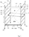
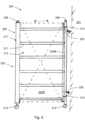
- Figs. 1-3 each show a scaffolding assembly 100, 200, 300 comprising a scaffold 103, 203, 303 for operable positioning at and/or against a part of a construction 201 (to be) worked on, e.g. (a wall of) a building (only shown in Fig. 2 ), and providing a work space W for a worker (not shown).
- Each shown scaffold 103, 203, 303 comprises a cover 105, 205, 305 for covering at least part of the respective work space W from an environment of the scaffold 103, 203, 303, and being discussed in more detail hereafter.
- cover fabric of the covers 105, 205, 305 is only indicated with broken lines so as to show the respective scaffold 103, 203, 303.
- Each shown scaffold 103, 203, 303 is, as an option, constructed of modular scaffolding, e.g. flooring member F, (only shown in Fig. 1 ) uprights 107, 207, 307 and horizontal trusses 109, 309 as exemplary scaffolding modules.
- the shown uprights 107, 207, 307 are formed ladder-like providing beams 108, 208, 308 supporting rungs 111, 211, 311 separated by gaps 113, 213, 313.
- the flooring member F and horizontal trusses 109, 309 are operably connected to (the rungs 111, 211, 311 of) the uprights 107, 207, 307.
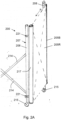
- Diagonal trusses 214 and/or further scaffolding modules may be provided as well ( Fig. 2A ).
- Such scaffold may be provided with wheels 115, 215 ( Figs. 1-2 ).
- such scaffold may be fixed to the construction 201 by anchors 220.
- the scaffolding assembly 100 of Fig. 1 comprises a roller device 117 horizontally mounted to the scaffolding, here, to rungs 111 of uprights 107 opposite each other, using mountings 121.
- the roller device 117 may serve as horizontal truss to the scaffold 103.
- the cover 105 may cover a side portion of the scaffold 103 for covering the work space W laterally, e.g. covering a back side of the scaffold 103 opposite the construction (not shown).
- the cover 105 is provided with an optional beam 115B, and hooks 119 are provided as optional fasteners for fastening an unrolled portion of the cover 105 to (a truss 109 of) the scaffold 103.
- Fig. 1A shows the scaffolding assembly 100 of Fig. 1 , provided with optional cover members 130 mounted to the scaffold, e.g. the uprights 108 as shown, for closing (potential) gaps between the scaffold 103 and the cover 105.
- the mounting may preferably be releasable, e.g. using one or more of hooks, clamps, bolts, etc.
- the cover members 130 may as options (shown), extend outside of the scaffold 103 and outside of the cover 105.
- Part of the cover members 130 may be provided by fabric portions and/or by rigid members such as plates and/or profiles, as shown, e.g. of metal (steel, aluminium) and/or wood and/or polymeric material.
- parts 131 of a cover member 130 may be movably connected together, e.g. foldably connected by means of one or more hinges. This may facilitate storage and/or transport.
- the scaffolding assembly 200 of Fig. 2 comprises a roller device 217 vertically mounted to the scaffolding, here, to a beam 208 of an upright 207, using mountings 221.
- a rollable portion 205R of the cover 205 may be reversibly (un-)rolled in a horizontal direction to (from) a rolled-up configuration from (to) an unrolled configuration for (un-)covering the at least part of the work space, as indicated in Fig. 2 .
- Fig. 2A shows part of the scaffolding assembly 300 from another viewing angle.
- the cover 205 may cover a side portion of the scaffold 203 for covering the work space W laterally e.g. covering a back side of the scaffold 103 opposite the construction (not shown).
- the scaffold 203 is secured to the construction 201 with optional anchors 220.
- the cover 305 may be provided with an optional beam (not shown) and/or fasteners (not shown) for fastening an unrolled portion of the cover 305 to (a truss 309 and/or beam 308 of) the scaffold 303.
- Figs. 4-6 show details of embodiments of a roller device 417, 517, 617.
- the roller devices 417, 517, 617 each comprise optional mountings 421, 521, 621 and are mountable to scaffolding to provide assembly as disclosed herein.
- the roller devices 417, 517, 617 is configured for, when mounted, reversibly (un-)rolling a rollable portion of a cover (not shown) to/from a rolled-up configuration from/to the unrolled configuration.
- the roller devices 417, 517, 617 comprise a housing 423, 523, 623 partly enclosing a rotatable core 425, 525, 625 for accommodating a rollable portion of a cover (not shown) rolled onto the core 425 in a rolled-up configuration while an unrolled portion of the cover may extend from the housing through an opening in the housing (not indicated).
- Fig. 7 is a cross section view of an embodiment of roller device 717 comprising a housing 723, accommodating a rotatable core 725 around which a rollable portion 705R of a cover 705 is wound. Part of the cover 705 extends from the housing 723 through an opening 743 in the housing 723. The housing 723 encloses the core 725 and the cover material rolled onto it for about 350 degrees around (an axis of rotation of) the core 725.
- the cover 705 is provided with a fortified portion 705F through which a hook 719 and/or clamp and/or other mounting is provided to fix the cover 705 to scaffolding.
Landscapes
- Engineering & Computer Science (AREA)
- Architecture (AREA)
- Mechanical Engineering (AREA)
- Civil Engineering (AREA)
- Structural Engineering (AREA)
- Movable Scaffolding (AREA)
Priority Applications (1)
| Application Number | Priority Date | Filing Date | Title |
|---|---|---|---|
| EP23150017.4A EP4394143A1 (fr) | 2023-01-02 | 2023-01-02 | Ensemble échafaudage |
Applications Claiming Priority (1)
| Application Number | Priority Date | Filing Date | Title |
|---|---|---|---|
| EP23150017.4A EP4394143A1 (fr) | 2023-01-02 | 2023-01-02 | Ensemble échafaudage |
Publications (1)
| Publication Number | Publication Date |
|---|---|
| EP4394143A1 true EP4394143A1 (fr) | 2024-07-03 |
Family
ID=84785308
Family Applications (1)
| Application Number | Title | Priority Date | Filing Date |
|---|---|---|---|
| EP23150017.4A Withdrawn EP4394143A1 (fr) | 2023-01-02 | 2023-01-02 | Ensemble échafaudage |
Country Status (1)
| Country | Link |
|---|---|
| EP (1) | EP4394143A1 (fr) |
Citations (5)
| Publication number | Priority date | Publication date | Assignee | Title |
|---|---|---|---|---|
| WO1986003538A1 (fr) * | 1984-12-06 | 1986-06-19 | Lennart Svensson | Dispositif de protection des echafaudages contre les intemperies |
| DE29611895U1 (de) * | 1996-07-09 | 1996-09-12 | Brückner, Heinz, 07937 Zeulenroda | Vorrichtung zum Aufrollen von Planen |
| DE202004016546U1 (de) * | 2004-10-26 | 2006-03-16 | Höller, Wilhelm | Gerüstverkleidungselement |
| KR101982334B1 (ko) * | 2018-12-14 | 2019-05-24 | 박재섭 | 고소작업대용 입식 천막장치 |
| DE202022106513U1 (de) * | 2022-11-22 | 2023-01-26 | Ismet Güler | Gerüst-Vorrichtung mit abnehmbarer Stützstrebe zur Aufnahme einer Rotationswelle einer Windschutzplane |
-
2023
- 2023-01-02 EP EP23150017.4A patent/EP4394143A1/fr not_active Withdrawn
Patent Citations (5)
| Publication number | Priority date | Publication date | Assignee | Title |
|---|---|---|---|---|
| WO1986003538A1 (fr) * | 1984-12-06 | 1986-06-19 | Lennart Svensson | Dispositif de protection des echafaudages contre les intemperies |
| DE29611895U1 (de) * | 1996-07-09 | 1996-09-12 | Brückner, Heinz, 07937 Zeulenroda | Vorrichtung zum Aufrollen von Planen |
| DE202004016546U1 (de) * | 2004-10-26 | 2006-03-16 | Höller, Wilhelm | Gerüstverkleidungselement |
| KR101982334B1 (ko) * | 2018-12-14 | 2019-05-24 | 박재섭 | 고소작업대용 입식 천막장치 |
| DE202022106513U1 (de) * | 2022-11-22 | 2023-01-26 | Ismet Güler | Gerüst-Vorrichtung mit abnehmbarer Stützstrebe zur Aufnahme einer Rotationswelle einer Windschutzplane |
Similar Documents
| Publication | Publication Date | Title |
|---|---|---|
| CA2182385C (fr) | Systeme de protection temporaire | |
| US5161641A (en) | Jointly movable safety net and curtain arrangement for multi-floor buildings under construction | |
| CA2051591C (fr) | Enceinte d'echafaudage | |
| JP3172719B2 (ja) | 建築工事用安全フェンス | |
| US5299655A (en) | Workplace support and enclosure | |
| WO1986003538A1 (fr) | Dispositif de protection des echafaudages contre les intemperies | |
| CA3105917C (fr) | Dispositif de protection de chantier de construction pour l`escalade de colonne, systeme et methode | |
| FI89894C (fi) | Saekerhetsanordning foer doerroeppningen till en hiss | |
| GB2355751A (en) | Scaffold guard having tensionable safety screen | |
| DE19543662A1 (de) | Spanngerüst für Fangnetze | |
| US3586126A (en) | Portable enclosure and method of erecting same | |
| WO2013061058A1 (fr) | Appareil d'échafaudage | |
| JP2764366B2 (ja) | 開閉機構を備えた仮設テント | |
| JP3416541B2 (ja) | 開閉装置の開閉体取付方法 | |
| KR20000009699A (ko) | 건축 공사용 안전펜스 | |
| JP2943564B2 (ja) | ゴンドラ装置 | |
| EP4549681A1 (fr) | Ensemble échafaudage | |
| JP2585174B2 (ja) | 仮設テント用足場の固定方法 | |
| WO2011061407A1 (fr) | Appareil permettant de recouvrir un mur | |
| JP7508068B2 (ja) | 屋外設置機器作業用テント装置 | |
| AU2015271969B2 (en) | Safety guard apparatus | |
| US20070071898A1 (en) | Overspray shield | |
| WO1997045595A1 (fr) | Station mobile pour travaux | |
| MX2013009945A (es) | Vivienda prefabricada modular. | |
| JP6793960B2 (ja) | 大型テント |
Legal Events
| Date | Code | Title | Description |
|---|---|---|---|
| PUAI | Public reference made under article 153(3) epc to a published international application that has entered the european phase |
Free format text: ORIGINAL CODE: 0009012 |
|
| STAA | Information on the status of an ep patent application or granted ep patent |
Free format text: STATUS: THE APPLICATION HAS BEEN PUBLISHED |
|
| AK | Designated contracting states |
Kind code of ref document: A1 Designated state(s): AL AT BE BG CH CY CZ DE DK EE ES FI FR GB GR HR HU IE IS IT LI LT LU LV MC ME MK MT NL NO PL PT RO RS SE SI SK SM TR |
|
| RAP3 | Party data changed (applicant data changed or rights of an application transferred) |
Owner name: S GEAR B.V. |
|
| RIN1 | Information on inventor provided before grant (corrected) |
Inventor name: OLIE, ERIC Inventor name: WESTERINK, JARDO |
|
| STAA | Information on the status of an ep patent application or granted ep patent |
Free format text: STATUS: THE APPLICATION IS DEEMED TO BE WITHDRAWN |
|
| 18D | Application deemed to be withdrawn |
Effective date: 20250104 |