EP4394191A2 - Verbindungsanordnung und möbel - Google Patents
Verbindungsanordnung und möbel Download PDFInfo
- Publication number
- EP4394191A2 EP4394191A2 EP24173067.0A EP24173067A EP4394191A2 EP 4394191 A2 EP4394191 A2 EP 4394191A2 EP 24173067 A EP24173067 A EP 24173067A EP 4394191 A2 EP4394191 A2 EP 4394191A2
- Authority
- EP
- European Patent Office
- Prior art keywords
- furniture part
- dowel
- along
- furniture
- longitudinal direction
- Prior art date
- Legal status (The legal status is an assumption and is not a legal conclusion. Google has not performed a legal analysis and makes no representation as to the accuracy of the status listed.)
- Pending
Links
Images




Classifications
-
- F—MECHANICAL ENGINEERING; LIGHTING; HEATING; WEAPONS; BLASTING
- F16—ENGINEERING ELEMENTS AND UNITS; GENERAL MEASURES FOR PRODUCING AND MAINTAINING EFFECTIVE FUNCTIONING OF MACHINES OR INSTALLATIONS; THERMAL INSULATION IN GENERAL
- F16B—DEVICES FOR FASTENING OR SECURING CONSTRUCTIONAL ELEMENTS OR MACHINE PARTS TOGETHER, e.g. NAILS, BOLTS, CIRCLIPS, CLAMPS, CLIPS OR WEDGES; JOINTS OR JOINTING
- F16B12/00—Jointing of furniture or the like, e.g. hidden from exterior
- F16B12/44—Leg joints; Corner joints
- F16B12/50—Metal corner connections
-
- F—MECHANICAL ENGINEERING; LIGHTING; HEATING; WEAPONS; BLASTING
- F16—ENGINEERING ELEMENTS AND UNITS; GENERAL MEASURES FOR PRODUCING AND MAINTAINING EFFECTIVE FUNCTIONING OF MACHINES OR INSTALLATIONS; THERMAL INSULATION IN GENERAL
- F16B—DEVICES FOR FASTENING OR SECURING CONSTRUCTIONAL ELEMENTS OR MACHINE PARTS TOGETHER, e.g. NAILS, BOLTS, CIRCLIPS, CLAMPS, CLIPS OR WEDGES; JOINTS OR JOINTING
- F16B12/00—Jointing of furniture or the like, e.g. hidden from exterior
- F16B12/10—Jointing of furniture or the like, e.g. hidden from exterior using pegs, bolts, tenons, clamps, clips, or the like
-
- F—MECHANICAL ENGINEERING; LIGHTING; HEATING; WEAPONS; BLASTING
- F16—ENGINEERING ELEMENTS AND UNITS; GENERAL MEASURES FOR PRODUCING AND MAINTAINING EFFECTIVE FUNCTIONING OF MACHINES OR INSTALLATIONS; THERMAL INSULATION IN GENERAL
- F16B—DEVICES FOR FASTENING OR SECURING CONSTRUCTIONAL ELEMENTS OR MACHINE PARTS TOGETHER, e.g. NAILS, BOLTS, CIRCLIPS, CLAMPS, CLIPS OR WEDGES; JOINTS OR JOINTING
- F16B12/00—Jointing of furniture or the like, e.g. hidden from exterior
- F16B12/10—Jointing of furniture or the like, e.g. hidden from exterior using pegs, bolts, tenons, clamps, clips, or the like
- F16B12/28—Jointing of furniture or the like, e.g. hidden from exterior using pegs, bolts, tenons, clamps, clips, or the like for metal furniture parts
- F16B12/34—Jointing of furniture or the like, e.g. hidden from exterior using pegs, bolts, tenons, clamps, clips, or the like for metal furniture parts using keyhole-shaped slots and pins
-
- F—MECHANICAL ENGINEERING; LIGHTING; HEATING; WEAPONS; BLASTING
- F16—ENGINEERING ELEMENTS AND UNITS; GENERAL MEASURES FOR PRODUCING AND MAINTAINING EFFECTIVE FUNCTIONING OF MACHINES OR INSTALLATIONS; THERMAL INSULATION IN GENERAL
- F16B—DEVICES FOR FASTENING OR SECURING CONSTRUCTIONAL ELEMENTS OR MACHINE PARTS TOGETHER, e.g. NAILS, BOLTS, CIRCLIPS, CLAMPS, CLIPS OR WEDGES; JOINTS OR JOINTING
- F16B12/00—Jointing of furniture or the like, e.g. hidden from exterior
- F16B12/10—Jointing of furniture or the like, e.g. hidden from exterior using pegs, bolts, tenons, clamps, clips, or the like
- F16B12/28—Jointing of furniture or the like, e.g. hidden from exterior using pegs, bolts, tenons, clamps, clips, or the like for metal furniture parts
- F16B12/36—Jointing of furniture or the like, e.g. hidden from exterior using pegs, bolts, tenons, clamps, clips, or the like for metal furniture parts using separate pins, dowels or the like
-
- A—HUMAN NECESSITIES
- A47—FURNITURE; DOMESTIC ARTICLES OR APPLIANCES; COFFEE MILLS; SPICE MILLS; SUCTION CLEANERS IN GENERAL
- A47B—TABLES; DESKS; OFFICE FURNITURE; CABINETS; DRAWERS; GENERAL DETAILS OF FURNITURE
- A47B2230/00—Furniture jointing; Furniture with such jointing
- A47B2230/0029—Dowels
- A47B2230/0037—Dowels or dowel-pins
-
- F—MECHANICAL ENGINEERING; LIGHTING; HEATING; WEAPONS; BLASTING
- F16—ENGINEERING ELEMENTS AND UNITS; GENERAL MEASURES FOR PRODUCING AND MAINTAINING EFFECTIVE FUNCTIONING OF MACHINES OR INSTALLATIONS; THERMAL INSULATION IN GENERAL
- F16B—DEVICES FOR FASTENING OR SECURING CONSTRUCTIONAL ELEMENTS OR MACHINE PARTS TOGETHER, e.g. NAILS, BOLTS, CIRCLIPS, CLAMPS, CLIPS OR WEDGES; JOINTS OR JOINTING
- F16B12/00—Jointing of furniture or the like, e.g. hidden from exterior
- F16B12/40—Joints for furniture tubing
-
- F—MECHANICAL ENGINEERING; LIGHTING; HEATING; WEAPONS; BLASTING
- F16—ENGINEERING ELEMENTS AND UNITS; GENERAL MEASURES FOR PRODUCING AND MAINTAINING EFFECTIVE FUNCTIONING OF MACHINES OR INSTALLATIONS; THERMAL INSULATION IN GENERAL
- F16B—DEVICES FOR FASTENING OR SECURING CONSTRUCTIONAL ELEMENTS OR MACHINE PARTS TOGETHER, e.g. NAILS, BOLTS, CIRCLIPS, CLAMPS, CLIPS OR WEDGES; JOINTS OR JOINTING
- F16B12/00—Jointing of furniture or the like, e.g. hidden from exterior
- F16B12/10—Jointing of furniture or the like, e.g. hidden from exterior using pegs, bolts, tenons, clamps, clips, or the like
- F16B2012/103—Sleeves or dowels for connection fittings
Definitions
- connection arrangement for connecting a third furniture part to a second furniture part.
- a dowel configured to be attached to a tubular furniture part, which may be said second furniture part.
- a connection arrangement for connecting the third furniture part to the second furniture part using the dowel is also disclosed.
- a furniture comprising a first furniture part, a second furniture part and a third furniture part, the furniture parts being connected to each other using said connection arrangements.
- connection arrangement for connecting a first furniture part to a second furniture part with a further furniture part , wherein the first furniture part comprises:
- a single furniture may comprise a first, a second and a third furniture part and include two or more of the different connection arrangements disclosed herein, the same label is used for the same part through-out the description and the claims rather than relabelling them in relation to the different connection arrangements.
- connection arrangement with the dowel, the through-going opening, the abutment surfaces of the first and second furniture part, and the connection member formed to interact with the dowel and the second side of the second furniture part, it is possible to provide a strong connection between the first and second furniture parts with a connection arrangement that may be assembled into a locking engagement without the use of any tools.
- the one or more abutment surfaces of the second furniture part may be formed of an outer surface forming the first side of the wall.
- connection arrangement for connecting a first furniture part to a second furniture part, wherein the first furniture part comprises:
- the second furniture part will thereby be correctly positioned and oriented relative to the first furniture part and the connection member may be moved with ease and still provide a strong and stable connection between the first and second furniture part.
- the one or more abutment surfaces of the second furniture part may be configured to be arranged inside and abut one or more abutments surfaces on an inside of the tubular section.
- Such a design provides a strong abutment surface, makes the abutment surface easy to manufacture and makes it possible to cover the connection arrangement inside the tubular section.
- the one or more abutment surfaces of the second furniture part may comprise a tubular section extending from the first side of the wall in the direction opposite the longitudinal direction and extending circumferentially around the through-going opening.
- the recess may have an entrance opening in a first surface forming a corner together with a second surface, the first surface being intended to face in the travel direction and the second surface being intended to face the wall of the second furniture part.
- a recess may be said to be an open ended recess. Designing the connection member with such a recess makes it easy to use; the user can position the first and second furniture parts in their intended position and then in a straight-forward motion push the connection member over the dowel such that the first and second furniture parts becomes interconnected. Such a design also facilitates manufacture of the connection member.
- the connection member may e.g. be injection moulded in a single step process since the entrance opening may be used as an extraction way for a removable core in an injection moulding tool with the core having the shape of the recess.
- the second furniture part may be a tubular member having an open end facing in a direction opposite the travel direction of the connection member and having a main extension along the transverse direction. This is advantageous in that the connection member may be inserted into the tubular member and be moved along the travel direction to the locking position in a single straight-forward motion.
- a dowel of this kind is easy to attach to a tubular furniture part and it is capable of providing a strong connection arrangement by being securely attached to the tubular furniture part and by presenting a connecting portion capable of providing a strong connection with a recess having internal ridges interacting with the ridge and valley of the connection portion.
- At least one end preferably both ends, as seen along the first transverse direction, of the neck portion, may have
- the head portion may be asymmetric in its design and the elongated opening may be asymmetric in its design such that the head of the dowel is only insertable with the first transverse direction in one of two opposing orientations in which the first transverse direction is aligned with or has a major component along the longitudinal direction of the elongated through-going hold.
- the dowel is only insertable in the orientation that will, in combination with the rotation blocking and rotation allowing corners result in the intended orientation of the dowel.
- the dowel is only insertable in the orientation that will, in combination with the rotation blocking and rotation allowing corners result in the intended orientation of the dowel.
- the second furniture part may be a tubular furniture part provided with an elongated through-going opening extending through a first wall of the tubular furniture part
- the dowel may be designed in accordance with the disclosure above in its most generic terms or in the preferred embodiments of the dowel.
- connection arrangement for connecting a third furniture part to a second furniture part
- connection member with such a designed recess and at least partly inserting it into the third furniture part in combination with the use of such a designed dowel it is possible to provide a strong connection of a tubular furniture part to a second furniture part and it is possible to provide a connection arrangement being covered by the tubular furniture part and a cover plate on the dowel.
- a single furniture may comprise a first, a second and a third furniture part and include the initially disclosed connection arrangement and also this immediately above disclosed connection arrangement, the same label is used for the same part through-out the description and the claims rather than relabelling them in relation to the different connection arrangements.
- the dowel may be rotated from the orientation it has when being inserted to an intended orientation in which the dowel is stopped from further rotation.
- both ends each provided with a rotation blocking corner and a rotation allowing corner wherein the two rotation blocking corners are arranged diagonally relative to each other and the two rotation allowing corners are arranged diagonally relative to each other.
- the head portion may be asymmetric in its design and the elongated opening may be asymmetric in its design such that the head of the dowel is only insertable with the first transverse direction in one of two opposing orientations in which the first transverse direction is aligned with or has a major component along the longitudinal direction of the elongated through-going hold.
- the second furniture part may be a tubular furniture part provided with an elongated through-going opening extending through a first wall of the tubular furniture part
- the dowel may be designed in accordance with the disclosure above in its most generic terms or in the preferred embodiments of the dowel.
- the elongated through-going opening preferably has a width along a transverse direction of the elongated through-going opening being greater than the extension of the head portion and neck portion along the second transverse direction and being smaller than the extension of the head portion along the first transverse direction.
- the inventive concept is realised in a furniture comprising a first furniture part, a second furniture part and a third furniture part, wherein the first and second furniture parts are connected to each other by the connection arrangement for connecting a first furniture part to a second furniture part as disclosed above in its most generic terms or in the preferred embodiments, and wherein the first and third furniture parts are connected to each other by the connection arrangement for connecting a second furniture part to a second furniture part as disclosed above in its most generic terms or in the preferred embodiments.
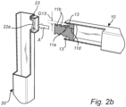
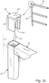
- connection arrangement for connecting a first furniture part 10 to a second furniture part 20.
- the first furniture part 10 is tubular and has a main extension along a longitudinal direction L.
- the first furniture part 10 comprises a dowel 11 and a tubular section 10a forming an abutment surface 13.
- the dowel 11 extends from the first furniture part 10 along a longitudinal direction L towards a free end 11c of the dowel 11.
- the dowel 11 has as e.g. indicated in figure 2c , two neck portions 11b.
- the abutment surface 13 has an extension in the longitudinal direction L along a base portion 11a of the dowel 11.
- the abutment surface 13 also extends circumferentially C around the dowel 11.
- the dowel 11 and the through-going opening 22 have a circular cross-section.
- the dowel 11 and the through-going opening 22 may basically have any desired cross-sectional shape.
- a circular shape is preferred from a manufacturing perspective.
- Non-circular shapes may be preferred from the perspective that non-circular shapes may be used to define a specific rotational relative orientation between the first and second furniture parts 10, 20 about the longitudinal direction L.
- the base portion 11a may form an abutment surface which, when the dowel 11 is inserted through the through-going opening 22 of the wall 21, abuts an inner surface 22a of the through-going opening 22.
- the third furniture part 40 is tubular and has a main extension along the longitudinal direction L.
- the third furniture part 40 has an open end 41 facing in the longitudinal direction L as shown in figure 3d .
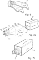
- the dowel 51 will in the following be disclosed in more detail with reference mainly to figures 3a-c .
- the dowel 51 is configured to be attached to a tubular furniture part 20 and to provide a part of a connection arrangement between the tubular furniture part 20 and a third furniture part 40.
- the dowel 51 comprises in short a connection portion 51' and an attachment portion 51".
- connection portion 51' has the above mentioned two ridges 51b each followed, as seen along the longitudinal direction L, by a valley 51c.
- the connection portion 51' is configured to extend from the second furniture part 20 along the direction L' opposite the longitudinal direction L towards the free end 51c of the dowel 51.
- the attachment portion 51" has a neck portion 52 followed, as seen along the longitudinal direction L, by a head portion 53.
- the head portion 53 has in a first transverse direction T' an extension being greater than an extension of the neck portion 52 in said first transverse direction T' and being greater than an extension of the head portion 53 and an extension of the neck portion 52 in a second transverse direction T" being orthogonal to the first transverse direction T'.
- the second furniture part 20 is provided with an elongated through-going opening 25 extending through a first wall 21 of the tubular furniture part 20.
- the elongated through-going opening 25 has, along its longitudinal extension, a width W (see Fig. 3g ) along a transverse direction T25 of the elongated through-going opening 25 being greater than the extension of the head portion 53 and neck portion 52 along the second transverse direction T" and being smaller than the extension of the head portion 53 along the first transverse direction T'.
- the dowel 51 is configured to be attached to the tubular furniture part 20 by
- the dowel 51 is shown in its attached position in figure 3c .
- the dowel 51 may be rotated from the orientation it has when being inserted to an intended orientation in which the dowel 51 is stopped from further rotation.
- the head portion 53 may be asymmetric in its design and the elongated opening 25 may be asymmetric in its design such that the head 53 of the dowel 51 is only insertable with the first transverse direction T' in one of two opposing orientations in which the first transverse direction T' is aligned with or has a major component along the longitudinal direction L25 of the elongated through-going hold 25.
- the dowel 51 is only insertable in the orientation that will, in combination with the rotation blocking 52a', 52b' and rotation allowing corners 52a", 52b" result in the intended orientation of the dowel 51.
- the inventive concept is realised in a furniture comprising a first furniture part 10, a second furniture part 20 and a third furniture part 40, wherein the first and second furniture parts 10, 20 are connected to each other by the connection arrangement for connecting a first furniture part 10 to a second furniture part 20 as disclosed above in its most generic terms or in the preferred embodiments, and wherein the first and third furniture parts 10, 40 are connected to each other by the connection arrangement for connecting a second furniture part 10 to a second furniture part 20 as disclosed above in its most generic terms or in the preferred embodiments.
- connection arrangement between a first furniture part 10 and a second furniture part 20 similar to the connection arrangement of figures 2a-e .
- a connection member 30 of figure 1 instead of using a connection member 30 of figure 1 , there is in this latter connection arrangement used a connection member 80 which is insertable or form part of a tubular member 70.
- the tubular member 70 is intended to extend as a continuation of the second furniture part 20.
- This design is e.g. suitable to provide a leg 70 at the bottom of the furniture.
- the connection member 80 is provided with a recess 31 of the kind disclosed in detail with reference to figure 1 .
- connection arrangement of figures 1 and 2a-e with the connection arrangement of figures 4a-c in a design where the furniture part 70 is provided with or receives a connection member 80 at one end thereof and is provided with a through-going opening 22 and abutment surfaces 23 at the other end thereof.
- a plurality of such furniture parts 70 may be stacked on top of each other and connect with a first furniture part 10 at each such interconnection.
- the connection arrangement could end with a connection arrangement as disclosed in figures 1 and 2a-e and at the bottom of such a stack the connection arrangement could end with a connection arrangement as disclosed in figures 4a-c .
- connection arrangement as shown in figures 4a-c may alternatively end at both ends of the second furniture part 20 with a connection arrangement of the kind disclosed in figures 1 and 2a-e .
- the various furniture parts 10, 20, 40 are formed of from a square or rectangular tube.
- the furniture parts do not have to be formed from tubes. They may be solid parts provided with recesses or openings providing the spaces or cavities necessary to receive the dowels, connecting members, etc., which spaces or cavities are provided by the interior of the tubes of the preferred embodiments.
- the shapes, of the tubular parts or solid parts need not be square or rectangular. Other shapes, such as other kinds of polygons, circles, ovals, ellipsoids, are also conceivable.
- the expression furniture part may relate to different kinds of furniture. It may e.g. relate to separate free standing furniture, such as shelves, book shelves, TV-benches, side boards, tables, cupboards, etc. It may also relate to built-in cabinets or shelves, such as wall-hanged kitchen cabinets, wall-hanged kitchen shelves, etc. It may also relate to semi-built-in cabinets or shelves, such as wall hanged TV-benches, etc. Irrespective of it is built-in or free standing it may not only relate to furniture designed for storage, such as cabinets and shelves, but may also relate to furniture parts for furniture for other kinds of use. It may e.g. relate to furniture for sitting, such as sofas, benches, chairs, etc.
Landscapes
- Engineering & Computer Science (AREA)
- General Engineering & Computer Science (AREA)
- Mechanical Engineering (AREA)
- Furniture Connections (AREA)
Applications Claiming Priority (3)
| Application Number | Priority Date | Filing Date | Title |
|---|---|---|---|
| SE1851077A SE542853C2 (en) | 2018-09-12 | 2018-09-12 | Connection arrangements, dowel and furniture |
| EP19860303.7A EP3850228B8 (de) | 2018-09-12 | 2019-09-05 | Möbel mit verbindungsanordnungen |
| PCT/SE2019/050835 WO2020055307A1 (en) | 2018-09-12 | 2019-09-05 | Connection arrangments, dowel and furniture |
Related Parent Applications (2)
| Application Number | Title | Priority Date | Filing Date |
|---|---|---|---|
| EP19860303.7A Division EP3850228B8 (de) | 2018-09-12 | 2019-09-05 | Möbel mit verbindungsanordnungen |
| EP19860303.7A Division-Into EP3850228B8 (de) | 2018-09-12 | 2019-09-05 | Möbel mit verbindungsanordnungen |
Publications (2)
| Publication Number | Publication Date |
|---|---|
| EP4394191A2 true EP4394191A2 (de) | 2024-07-03 |
| EP4394191A3 EP4394191A3 (de) | 2024-12-25 |
Family
ID=69778206
Family Applications (2)
| Application Number | Title | Priority Date | Filing Date |
|---|---|---|---|
| EP24173067.0A Pending EP4394191A3 (de) | 2018-09-12 | 2019-09-05 | Verbindungsanordnung und möbel |
| EP19860303.7A Active EP3850228B8 (de) | 2018-09-12 | 2019-09-05 | Möbel mit verbindungsanordnungen |
Family Applications After (1)
| Application Number | Title | Priority Date | Filing Date |
|---|---|---|---|
| EP19860303.7A Active EP3850228B8 (de) | 2018-09-12 | 2019-09-05 | Möbel mit verbindungsanordnungen |
Country Status (5)
| Country | Link |
|---|---|
| US (4) | US11674539B2 (de) |
| EP (2) | EP4394191A3 (de) |
| CN (1) | CN112689715A (de) |
| SE (1) | SE542853C2 (de) |
| WO (1) | WO2020055307A1 (de) |
Families Citing this family (1)
| Publication number | Priority date | Publication date | Assignee | Title |
|---|---|---|---|---|
| CZ309779B6 (cs) * | 2021-09-02 | 2023-10-04 | Univerzita Karlova | Modulární konstrukční spojka pro spojování konstrukčních profilů do nosných koster různých tvarů |
Family Cites Families (16)
| Publication number | Priority date | Publication date | Assignee | Title |
|---|---|---|---|---|
| US3159440A (en) * | 1963-03-14 | 1964-12-01 | Educators Mfg Company | Cabinet wall panels and connecting means therefor |
| BE677183A (de) * | 1965-03-01 | 1966-07-18 | ||
| DE2546751A1 (de) | 1975-10-18 | 1977-04-21 | Heinze Fa R | Beschlag zum loesbaren verbinden zweier bauteile, insbesondere zum loesbaren verbinden zweier senkrecht aufeinanderstossener plattenfoermiger bauteile |
| JPS6019806U (ja) | 1983-07-19 | 1985-02-12 | 日本プライメタル株式会社 | 管状部材の接続装置 |
| US4676040A (en) * | 1985-01-07 | 1987-06-30 | Tandem Computers Incorporated | Structural support and thin panel assembly |
| US4770560A (en) | 1987-05-29 | 1988-09-13 | Ott Donald E | Self-tapping connector |
| US6347592B1 (en) * | 1998-01-13 | 2002-02-19 | Roy E. Gessert | Modular workbench and kit therefor |
| FR2806114B1 (fr) | 2000-03-09 | 2002-12-06 | Daniel Chaudoreille | Brique d'encastrement |
| ITRN20020002A1 (it) * | 2002-01-18 | 2003-07-18 | Mep S P A | Giunto modulare per connessione strutturale, in particolare per la costruzione di scaffalature. |
| DE102007058662A1 (de) * | 2007-12-06 | 2009-06-10 | Adam Mathes | Steckverbindungssystem mit einem Steckteil und einem Aufnahmeteil |
| ITMI20081847A1 (it) * | 2008-10-17 | 2010-04-18 | Manufatti Plastici Traversa S P A | Dispositivo di giunzione per elementi costruttivi di mobili |
| US20100307995A1 (en) * | 2009-06-05 | 2010-12-09 | Honey-Can-Do International Llc | Laundry Stand |
| IT1408030B1 (it) * | 2011-02-28 | 2014-05-30 | Brescancin S R L | Dispositivo di collegamento per un telaio e procedimento di montaggio di tale dispositivo |
| SE539966C2 (en) * | 2015-07-02 | 2018-02-13 | Ikea Supply Ag | Beam connector system for connecting a structural element to a beam, a furniture and a kit comprising a flat package and a furniture frame |
| SE540554C2 (en) * | 2015-12-16 | 2018-10-02 | Ikea Supply Ag | Attachment arrangement and piece of furniture |
| CN106337863A (zh) * | 2016-11-29 | 2017-01-18 | 李明 | 方便拆装的家具部件间无痕连接结构 |
-
2018
- 2018-09-12 SE SE1851077A patent/SE542853C2/en unknown
-
2019
- 2019-09-05 CN CN201980059532.3A patent/CN112689715A/zh active Pending
- 2019-09-05 US US17/274,472 patent/US11674539B2/en active Active
- 2019-09-05 EP EP24173067.0A patent/EP4394191A3/de active Pending
- 2019-09-05 WO PCT/SE2019/050835 patent/WO2020055307A1/en not_active Ceased
- 2019-09-05 EP EP19860303.7A patent/EP3850228B8/de active Active
-
2023
- 2023-04-28 US US18/141,169 patent/US12012982B2/en active Active
-
2024
- 2024-05-13 US US18/662,080 patent/US12258984B2/en active Active
-
2025
- 2025-02-13 US US19/053,016 patent/US20250251004A1/en active Pending
Also Published As
| Publication number | Publication date |
|---|---|
| SE542853C2 (en) | 2020-07-21 |
| US20230265875A1 (en) | 2023-08-24 |
| US12012982B2 (en) | 2024-06-18 |
| US20240295232A1 (en) | 2024-09-05 |
| WO2020055307A1 (en) | 2020-03-19 |
| US20250251004A1 (en) | 2025-08-07 |
| EP3850228B1 (de) | 2024-05-01 |
| EP3850228A1 (de) | 2021-07-21 |
| EP3850228C0 (de) | 2024-05-01 |
| SE1851077A1 (en) | 2020-03-13 |
| CN112689715A (zh) | 2021-04-20 |
| US11674539B2 (en) | 2023-06-13 |
| EP3850228A4 (de) | 2022-06-01 |
| US20220049734A1 (en) | 2022-02-17 |
| EP3850228B8 (de) | 2024-07-03 |
| US12258984B2 (en) | 2025-03-25 |
| EP4394191A3 (de) | 2024-12-25 |
Similar Documents
| Publication | Publication Date | Title |
|---|---|---|
| CN101443089B (zh) | 构造系统 | |
| EP2802240B1 (de) | Möbelscharnier | |
| EP2241216A1 (de) | Montagesystem zum Verbinden von Möbelelementen | |
| EP2713817B1 (de) | Zusammenbau einer schublade | |
| CN111742153B (zh) | 连接件和矩形连接结构 | |
| CN108601984B (zh) | 模块框架连接件以及使用这些连接件的系统 | |
| EP3301312A1 (de) | Mechanisches verschlusssystem für möbelplatten | |
| US20250251004A1 (en) | Connection arrangements, dowel and furniture | |
| US7365268B2 (en) | Storage receptacle | |
| KR101229705B1 (ko) | 조립식 가구 | |
| US20120308300A1 (en) | Assembly system for connecting furniture elements | |
| US20130236243A1 (en) | Connectors for Furniture and Other Objects | |
| CN120548417A (zh) | 用于镶板的连接装置 | |
| US10167108B2 (en) | Adjustable attachment clip for a shipping crate | |
| GB2428078A (en) | Joint for interconnecting furniture panels | |
| US20090120333A1 (en) | Molded pin for coupling two or more members | |
| JP2589778Y2 (ja) | 箱体構造 | |
| EP2618007A1 (de) | Verbindung von zwei rechteckigen Elementen | |
| EA040753B1 (ru) | Набор панелей с механическим блокирующим устройством |
Legal Events
| Date | Code | Title | Description |
|---|---|---|---|
| PUAI | Public reference made under article 153(3) epc to a published international application that has entered the european phase |
Free format text: ORIGINAL CODE: 0009012 |
|
| STAA | Information on the status of an ep patent application or granted ep patent |
Free format text: STATUS: THE APPLICATION HAS BEEN PUBLISHED |
|
| AC | Divisional application: reference to earlier application |
Ref document number: 3850228 Country of ref document: EP Kind code of ref document: P |
|
| AK | Designated contracting states |
Kind code of ref document: A2 Designated state(s): AL AT BE BG CH CY CZ DE DK EE ES FI FR GB GR HR HU IE IS IT LI LT LU LV MC MK MT NL NO PL PT RO RS SE SI SK SM TR |
|
| REG | Reference to a national code |
Ref country code: DE Ref legal event code: R079 Free format text: PREVIOUS MAIN CLASS: F16B0012340000 Ipc: F16B0012100000 |
|
| PUAL | Search report despatched |
Free format text: ORIGINAL CODE: 0009013 |
|
| AK | Designated contracting states |
Kind code of ref document: A3 Designated state(s): AL AT BE BG CH CY CZ DE DK EE ES FI FR GB GR HR HU IE IS IT LI LT LU LV MC MK MT NL NO PL PT RO RS SE SI SK SM TR |
|
| RIC1 | Information provided on ipc code assigned before grant |
Ipc: F16B 12/34 20060101ALI20241121BHEP Ipc: F16B 12/40 20060101ALI20241121BHEP Ipc: F16B 12/10 20060101AFI20241121BHEP |
|
| STAA | Information on the status of an ep patent application or granted ep patent |
Free format text: STATUS: REQUEST FOR EXAMINATION WAS MADE |
|
| 17P | Request for examination filed |
Effective date: 20250624 |
|
| GRAP | Despatch of communication of intention to grant a patent |
Free format text: ORIGINAL CODE: EPIDOSNIGR1 |
|
| STAA | Information on the status of an ep patent application or granted ep patent |
Free format text: STATUS: GRANT OF PATENT IS INTENDED |
|
| RIC1 | Information provided on ipc code assigned before grant |
Ipc: F16B 12/10 20060101AFI20251112BHEP Ipc: F16B 12/40 20060101ALI20251112BHEP Ipc: F16B 12/34 20060101ALI20251112BHEP |
|
| INTG | Intention to grant announced |
Effective date: 20251127 |
|
| GRAJ | Information related to disapproval of communication of intention to grant by the applicant or resumption of examination proceedings by the epo deleted |
Free format text: ORIGINAL CODE: EPIDOSDIGR1 |
|
| STAA | Information on the status of an ep patent application or granted ep patent |
Free format text: STATUS: REQUEST FOR EXAMINATION WAS MADE |
|
| GRAP | Despatch of communication of intention to grant a patent |
Free format text: ORIGINAL CODE: EPIDOSNIGR1 |
|
| STAA | Information on the status of an ep patent application or granted ep patent |
Free format text: STATUS: GRANT OF PATENT IS INTENDED |
|
| INTC | Intention to grant announced (deleted) | ||
| INTG | Intention to grant announced |
Effective date: 20260330 |