EP4394197A1 - Dispositif coulissant - Google Patents
Dispositif coulissant Download PDFInfo
- Publication number
- EP4394197A1 EP4394197A1 EP22861589.4A EP22861589A EP4394197A1 EP 4394197 A1 EP4394197 A1 EP 4394197A1 EP 22861589 A EP22861589 A EP 22861589A EP 4394197 A1 EP4394197 A1 EP 4394197A1
- Authority
- EP
- European Patent Office
- Prior art keywords
- rail member
- sliding device
- ball
- disposed
- upper portion
- Prior art date
- Legal status (The legal status is an assumption and is not a legal conclusion. Google has not performed a legal analysis and makes no representation as to the accuracy of the status listed.)
- Pending
Links
Images





Classifications
-
- A—HUMAN NECESSITIES
- A47—FURNITURE; DOMESTIC ARTICLES OR APPLIANCES; COFFEE MILLS; SPICE MILLS; SUCTION CLEANERS IN GENERAL
- A47B—TABLES; DESKS; OFFICE FURNITURE; CABINETS; DRAWERS; GENERAL DETAILS OF FURNITURE
- A47B88/00—Drawers for tables, cabinets or like furniture; Guides for drawers
- A47B88/40—Sliding drawers; Slides or guides therefor
- A47B88/483—Sliding drawers; Slides or guides therefor with single extensible guides or parts
- A47B88/487—Sliding drawers; Slides or guides therefor with single extensible guides or parts with rollers, ball bearings, wheels, or the like
-
- A—HUMAN NECESSITIES
- A47—FURNITURE; DOMESTIC ARTICLES OR APPLIANCES; COFFEE MILLS; SPICE MILLS; SUCTION CLEANERS IN GENERAL
- A47B—TABLES; DESKS; OFFICE FURNITURE; CABINETS; DRAWERS; GENERAL DETAILS OF FURNITURE
- A47B88/00—Drawers for tables, cabinets or like furniture; Guides for drawers
- A47B88/40—Sliding drawers; Slides or guides therefor
- A47B88/437—Rollers for slides or guides
-
- F—MECHANICAL ENGINEERING; LIGHTING; HEATING; WEAPONS; BLASTING
- F16—ENGINEERING ELEMENTS AND UNITS; GENERAL MEASURES FOR PRODUCING AND MAINTAINING EFFECTIVE FUNCTIONING OF MACHINES OR INSTALLATIONS; THERMAL INSULATION IN GENERAL
- F16C—SHAFTS; FLEXIBLE SHAFTS; ELEMENTS OR CRANKSHAFT MECHANISMS; ROTARY BODIES OTHER THAN GEARING ELEMENTS; BEARINGS
- F16C29/00—Bearings for parts moving only linearly
-
- F—MECHANICAL ENGINEERING; LIGHTING; HEATING; WEAPONS; BLASTING
- F16—ENGINEERING ELEMENTS AND UNITS; GENERAL MEASURES FOR PRODUCING AND MAINTAINING EFFECTIVE FUNCTIONING OF MACHINES OR INSTALLATIONS; THERMAL INSULATION IN GENERAL
- F16C—SHAFTS; FLEXIBLE SHAFTS; ELEMENTS OR CRANKSHAFT MECHANISMS; ROTARY BODIES OTHER THAN GEARING ELEMENTS; BEARINGS
- F16C29/00—Bearings for parts moving only linearly
- F16C29/005—Guide rails or tracks for a linear bearing, i.e. adapted for movement of a carriage or bearing body there along
-
- F—MECHANICAL ENGINEERING; LIGHTING; HEATING; WEAPONS; BLASTING
- F16—ENGINEERING ELEMENTS AND UNITS; GENERAL MEASURES FOR PRODUCING AND MAINTAINING EFFECTIVE FUNCTIONING OF MACHINES OR INSTALLATIONS; THERMAL INSULATION IN GENERAL
- F16C—SHAFTS; FLEXIBLE SHAFTS; ELEMENTS OR CRANKSHAFT MECHANISMS; ROTARY BODIES OTHER THAN GEARING ELEMENTS; BEARINGS
- F16C29/00—Bearings for parts moving only linearly
- F16C29/04—Ball or roller bearings
-
- F—MECHANICAL ENGINEERING; LIGHTING; HEATING; WEAPONS; BLASTING
- F16—ENGINEERING ELEMENTS AND UNITS; GENERAL MEASURES FOR PRODUCING AND MAINTAINING EFFECTIVE FUNCTIONING OF MACHINES OR INSTALLATIONS; THERMAL INSULATION IN GENERAL
- F16C—SHAFTS; FLEXIBLE SHAFTS; ELEMENTS OR CRANKSHAFT MECHANISMS; ROTARY BODIES OTHER THAN GEARING ELEMENTS; BEARINGS
- F16C29/00—Bearings for parts moving only linearly
- F16C29/04—Ball or roller bearings
- F16C29/048—Ball or roller bearings with thin walled races, e.g. tracks of sheet metal
-
- A—HUMAN NECESSITIES
- A47—FURNITURE; DOMESTIC ARTICLES OR APPLIANCES; COFFEE MILLS; SPICE MILLS; SUCTION CLEANERS IN GENERAL
- A47B—TABLES; DESKS; OFFICE FURNITURE; CABINETS; DRAWERS; GENERAL DETAILS OF FURNITURE
- A47B2210/00—General construction of drawers, guides and guide devices
- A47B2210/0002—Guide construction for drawers
- A47B2210/0029—Guide bearing means
- A47B2210/0032—Balls
- A47B2210/0035—Balls cages therefor, e.g. for telescopic slides
Definitions
- the present invention relates to a sliding device, and more specifically, to a sliding device with a two-stage rail structure and improved tilting stability under a load.
- a drawer assembly is provided with a sliding device so that a drawer can be easily drawn out from the mounting structure and returned to its original position.
- the sliding device is provided with a rolling means in the form of balls or rollers, and thus it can move more smoothly during sliding to improve user convenience.
- a sliding device consists of a fixed rail fixed to a wall surface of the drawer installation space and one or more moving rails slidably installed with respect to the fixed rail. That is, such a sliding device for guiding a drawer includes, for example, a two-stage folding type and a three-stage folding type.
- the fixed rail on a main body is fixed to an inner wall surface of a refrigerator or an inner surface of general furniture, and the moving rail on the drawer side is fixed to a receiving body. Therefore, the drawer can be easily slidably drawn in and out the moving rail with respect to the fixed rail.
- Patent Document 1 U.S. Patent Publication No. 6132020 (October 17, 2000 )
- the present invention is directed to providing a sliding device with a two-stage rail structure and improved tilting stability under a load.
- An aspect of the present invention provides a sliding device including a first rail member having one open side surface, a second rail member configured to slidably move on the first rail member and having one open side surface, and ball members disposed between the first rail member and the second rail member and including one or more ball members on a cross section, wherein the first rail member and the second rail member are disposed to engage with each other through the open one side surfaces.
- a first ball may be disposed between the first upper portion and the second upper portion
- a second ball may be disposed between the first lower portion and the second lower portion
- an angle ( ⁇ ) formed by the line (a) connecting centers of the first ball and the second ball and the first lower portion or the second upper portion may be an acute angle
- a first insertion portion on which the first ball is seated may be formed to be inserted into and disposed within the second rail member.
- a third ball may be disposed between an upper side of the second lower portion and a lower side of the first insertion portion.
- a second insertion portion on which the second ball is seated may be formed to be inserted into and disposed within the first rail member.
- the retainer may be formed in an "S" shape.
- a cross section of the retainer may be structured to be 180° rotationally symmetrical with respect to the center G.
- the first rail member and the second rail member may be disposed complementary to each other through the open one side surfaces.
- an outline of a cross section of the first insertion portion may be formed as a closed curve, the first insertion portion may be provided as a solid piece, and a first track groove on which the first ball is seated may be formed in an upper side of the first insertion portion.
- an outline of a cross section of the second insertion portion may be formed as a closed curve, the second insertion portion may be provided as a solid piece, and a second track groove on which the second ball is seated may be formed in a lower side of the second insertion portion.
- the overall size of a cross section of the structure can be minimized through efficient space utilization between rail members.
- FIG. 1 is a perspective view of a sliding device according to a first embodiment of the present invention
- FIG. 2 is an exploded perspective view of the sliding device according to the first embodiment of the present invention
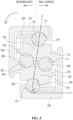
- FIG. 3 is a cross-sectional view of the sliding device according to the first embodiment of the present invention
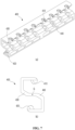
- FIG. 4 is a perspective view of a first rail member according to the first embodiment of the present invention
- FIG. 5 is a perspective view of a second rail member according to the first embodiment of the present invention.
- the sliding device 1000 of the present invention includes a first rail member 100, a second rail member 200, a ball member 300, and a retainer 400.
- the sliding device 1000 is configured so that rolling means such as ball members 300 are installed between the first rail member 100 and the second rail member 200 to reduce the frictional force between the rails. Thereby, the sliding device 1000 enables smoother siding movement.
- the first rail member 100 and the second rail member 200 are complementarily arranged to engage with each other through the open one side surface.
- the first rail member 100 and the second rail member 200 may have cross-sections that are symmetrical to each other in a diagonal direction.
- the first rail member 100 includes a first upper portion 110, a first side portion 120 connected to the first upper portion 100, and a first lower portion 130 connected to the first side portion 120.
- a first ball 310 is disposed between the first upper portion 110 and the second upper portion 210
- a second ball 320 is disposed between the first lower portion 130 and the second lower portion 230.
- an angle ⁇ formed by the line a connecting the centers of the first ball 310 and the second ball 320 and the first lower portion 130 or the second upper portion 210 may be an acute angle, a right angle, or an obtuse angle.
- a first insertion portion 140 that is inserted into the second rail member 200 and on which the first ball 310 is seated may be formed.
- the outline of a cross section of the first insertion portion 140 may be formed as a closed curve, the first insertion portion 140 may be provided as a solid piece, and a first track groove 141 on which the first ball 310 is seated may be formed in an upper side of the first insertion portion 140.
- the first insertion portion 140 may be formed to have a thicker cross-sectional shape than the first upper portion 110, the first side portion 120, and the first lower portion 130, thereby making it easier to support a load applied to the sliding device 1000.
- a fourth raceway is formed between a fifth track groove 242 formed in an upper side of the second insertion portion 240 and a sixth track groove 111 formed in a lower side of the first upper portion 110, and a fourth ball 340 may be disposed in the fourth raceway.
Landscapes
- Engineering & Computer Science (AREA)
- General Engineering & Computer Science (AREA)
- Mechanical Engineering (AREA)
- Drawers Of Furniture (AREA)
- Bearings For Parts Moving Linearly (AREA)
Applications Claiming Priority (2)
| Application Number | Priority Date | Filing Date | Title |
|---|---|---|---|
| KR1020210111134A KR102640768B1 (ko) | 2021-08-23 | 2021-08-23 | 슬라이딩 장치 |
| PCT/KR2022/011657 WO2023027378A1 (fr) | 2021-08-23 | 2022-08-05 | Dispositif coulissant |
Publications (2)
| Publication Number | Publication Date |
|---|---|
| EP4394197A1 true EP4394197A1 (fr) | 2024-07-03 |
| EP4394197A4 EP4394197A4 (fr) | 2024-12-25 |
Family
ID=85323263
Family Applications (1)
| Application Number | Title | Priority Date | Filing Date |
|---|---|---|---|
| EP22861589.4A Pending EP4394197A4 (fr) | 2021-08-23 | 2022-08-05 | Dispositif coulissant |
Country Status (4)
| Country | Link |
|---|---|
| US (1) | US20240365976A1 (fr) |
| EP (1) | EP4394197A4 (fr) |
| KR (1) | KR102640768B1 (fr) |
| WO (1) | WO2023027378A1 (fr) |
Families Citing this family (1)
| Publication number | Priority date | Publication date | Assignee | Title |
|---|---|---|---|---|
| EP4322289A4 (fr) | 2022-03-31 | 2025-01-01 | LG Energy Solution, Ltd. | Module de batterie à sécurité améliorée |
Family Cites Families (10)
| Publication number | Priority date | Publication date | Assignee | Title |
|---|---|---|---|---|
| DE9014756U1 (de) * | 1989-11-03 | 1991-01-03 | Schock Metallwerk GmbH, 7068 Urbach | Auszug |
| DE29807540U1 (de) | 1998-04-29 | 1998-06-10 | Paul Hettich Gmbh & Co., 32278 Kirchlengern | Schubkastenauszugführung |
| KR200291086Y1 (ko) * | 2002-06-19 | 2002-10-09 | 정두영 | 서랍용 볼레일 |
| KR100854631B1 (ko) * | 2005-10-26 | 2008-08-27 | 박윤식 | 2단 접철형 슬라이드 |
| MX336445B (es) * | 2008-12-31 | 2016-01-20 | Segos Co Ltd | Dispositivo deslizante. |
| KR20100127442A (ko) * | 2009-05-26 | 2010-12-06 | 옥기수 | 상하부 대칭형 슬라이드 레일의 구조 |
| CN104320993B (zh) * | 2012-03-22 | 2018-02-09 | 托马斯瑞胡国际有限公司 | 引导件、用于引导件的支承装置以及用以形成用于引导件的支承装置的方法和部件 |
| DE102013109380A1 (de) * | 2013-08-29 | 2015-03-05 | Rennerich Gmbh | Linearführungsvorrichtung |
| KR102089292B1 (ko) * | 2017-11-28 | 2020-03-16 | (주)세고스 | 슬라이드 유닛 |
| KR20220055898A (ko) * | 2020-10-27 | 2022-05-04 | (주)세고스 | 슬라이딩 장치 |
-
2021
- 2021-08-23 KR KR1020210111134A patent/KR102640768B1/ko active Active
-
2022
- 2022-08-05 EP EP22861589.4A patent/EP4394197A4/fr active Pending
- 2022-08-05 US US18/685,795 patent/US20240365976A1/en active Pending
- 2022-08-05 WO PCT/KR2022/011657 patent/WO2023027378A1/fr not_active Ceased
Also Published As
| Publication number | Publication date |
|---|---|
| KR20230029081A (ko) | 2023-03-03 |
| US20240365976A1 (en) | 2024-11-07 |
| WO2023027378A1 (fr) | 2023-03-02 |
| KR102640768B1 (ko) | 2024-02-27 |
| EP4394197A4 (fr) | 2024-12-25 |
Similar Documents
| Publication | Publication Date | Title |
|---|---|---|
| US4659237A (en) | Drawer guide | |
| JP4545935B2 (ja) | 引出し摺動体軸受保持具及び案内ブロック | |
| US6347849B1 (en) | Pull-out slide for drawer or the like | |
| CN112392343B (zh) | 门限位器和将门保持在期望的打开位置的方法 | |
| US5757109A (en) | Telescopic drawer slide with soft sequencing latch | |
| EP2839760A1 (fr) | Dispositif coulissant de tiroir | |
| US8430567B2 (en) | Load adaptive roller carriage assembly | |
| US20120027325A1 (en) | Slide assembly with dual handed ball retainer latch | |
| US20010035704A1 (en) | Ball bearing slide assembly | |
| US4955160A (en) | Guide wall assembly for drawers | |
| US5895101A (en) | Drawer slide | |
| EP4394197A1 (fr) | Dispositif coulissant | |
| WO2007108601A1 (fr) | Glissière de montage en partie inférieure | |
| US12543854B2 (en) | Sliding device | |
| KR200452662Y1 (ko) | 서랍안내용 레일부재 | |
| US5421653A (en) | Slide system | |
| WO2008072868A1 (fr) | Mécanisme de blocage et glissière ainsi pourvue | |
| US10842267B2 (en) | Movement mechanism for a guidance system | |
| KR102923826B1 (ko) | 슬라이드 레일 조립체 및 이를 포함하는 인출 시스템 | |
| KR20070044875A (ko) | 3단 접철형 슬라이드 | |
| KR100854631B1 (ko) | 2단 접철형 슬라이드 | |
| KR20240156858A (ko) | 슬라이드 장치 | |
| JPH11127996A (ja) | トレー引出し装置 |
Legal Events
| Date | Code | Title | Description |
|---|---|---|---|
| STAA | Information on the status of an ep patent application or granted ep patent |
Free format text: STATUS: THE INTERNATIONAL PUBLICATION HAS BEEN MADE |
|
| PUAI | Public reference made under article 153(3) epc to a published international application that has entered the european phase |
Free format text: ORIGINAL CODE: 0009012 |
|
| STAA | Information on the status of an ep patent application or granted ep patent |
Free format text: STATUS: REQUEST FOR EXAMINATION WAS MADE |
|
| 17P | Request for examination filed |
Effective date: 20240301 |
|
| AK | Designated contracting states |
Kind code of ref document: A1 Designated state(s): AL AT BE BG CH CY CZ DE DK EE ES FI FR GB GR HR HU IE IS IT LI LT LU LV MC MK MT NL NO PL PT RO RS SE SI SK SM TR |
|
| DAV | Request for validation of the european patent (deleted) | ||
| DAX | Request for extension of the european patent (deleted) | ||
| A4 | Supplementary search report drawn up and despatched |
Effective date: 20241126 |
|
| RIC1 | Information provided on ipc code assigned before grant |
Ipc: F16C 29/00 20060101ALI20241120BHEP Ipc: A47B 88/487 20170101ALI20241120BHEP Ipc: F16C 29/04 20060101AFI20241120BHEP |
|
| STAA | Information on the status of an ep patent application or granted ep patent |
Free format text: STATUS: EXAMINATION IS IN PROGRESS |
|
| 17Q | First examination report despatched |
Effective date: 20251020 |