EP4394232A1 - Support de montage et ensemble capteur - Google Patents
Support de montage et ensemble capteur Download PDFInfo
- Publication number
- EP4394232A1 EP4394232A1 EP23307306.3A EP23307306A EP4394232A1 EP 4394232 A1 EP4394232 A1 EP 4394232A1 EP 23307306 A EP23307306 A EP 23307306A EP 4394232 A1 EP4394232 A1 EP 4394232A1
- Authority
- EP
- European Patent Office
- Prior art keywords
- mounting
- region
- mounting bracket
- mounting surface
- bracket
- Prior art date
- Legal status (The legal status is an assumption and is not a legal conclusion. Google has not performed a legal analysis and makes no representation as to the accuracy of the status listed.)
- Granted
Links
Images



Classifications
-
- F—MECHANICAL ENGINEERING; LIGHTING; HEATING; WEAPONS; BLASTING
- F16—ENGINEERING ELEMENTS AND UNITS; GENERAL MEASURES FOR PRODUCING AND MAINTAINING EFFECTIVE FUNCTIONING OF MACHINES OR INSTALLATIONS; THERMAL INSULATION IN GENERAL
- F16M—FRAMES, CASINGS OR BEDS OF ENGINES, MACHINES OR APPARATUS, NOT SPECIFIC TO ENGINES, MACHINES OR APPARATUS PROVIDED FOR ELSEWHERE; STANDS; SUPPORTS
- F16M13/00—Other supports for positioning apparatus or articles; Means for steadying hand-held apparatus or articles
- F16M13/02—Other supports for positioning apparatus or articles; Means for steadying hand-held apparatus or articles for supporting on, or attaching to, an object, e.g. tree, gate, window-frame, cycle
- F16M13/027—Ceiling supports
-
- F—MECHANICAL ENGINEERING; LIGHTING; HEATING; WEAPONS; BLASTING
- F16—ENGINEERING ELEMENTS AND UNITS; GENERAL MEASURES FOR PRODUCING AND MAINTAINING EFFECTIVE FUNCTIONING OF MACHINES OR INSTALLATIONS; THERMAL INSULATION IN GENERAL
- F16M—FRAMES, CASINGS OR BEDS OF ENGINES, MACHINES OR APPARATUS, NOT SPECIFIC TO ENGINES, MACHINES OR APPARATUS PROVIDED FOR ELSEWHERE; STANDS; SUPPORTS
- F16M13/00—Other supports for positioning apparatus or articles; Means for steadying hand-held apparatus or articles
- F16M13/02—Other supports for positioning apparatus or articles; Means for steadying hand-held apparatus or articles for supporting on, or attaching to, an object, e.g. tree, gate, window-frame, cycle
-
- F—MECHANICAL ENGINEERING; LIGHTING; HEATING; WEAPONS; BLASTING
- F16—ENGINEERING ELEMENTS AND UNITS; GENERAL MEASURES FOR PRODUCING AND MAINTAINING EFFECTIVE FUNCTIONING OF MACHINES OR INSTALLATIONS; THERMAL INSULATION IN GENERAL
- F16M—FRAMES, CASINGS OR BEDS OF ENGINES, MACHINES OR APPARATUS, NOT SPECIFIC TO ENGINES, MACHINES OR APPARATUS PROVIDED FOR ELSEWHERE; STANDS; SUPPORTS
- F16M13/00—Other supports for positioning apparatus or articles; Means for steadying hand-held apparatus or articles
- F16M13/02—Other supports for positioning apparatus or articles; Means for steadying hand-held apparatus or articles for supporting on, or attaching to, an object, e.g. tree, gate, window-frame, cycle
- F16M13/025—Corner supports
Definitions
- sensing devices such as motion sensors may be utilized to sense people's activities or other conditions in an area or space for intelligent control in terms of lighting, household appliances, etc. to provide convenience for people's work and life.
- the second sub-region of the second mounting region is provided with an opening to enable the conductor wires or wire conduits to pass through the mounting bracket from a side of the second surface to a side of the first surface.
- the conductor wires or wire conduits may be enabled to pass through the interior of the mounting bracket to reach the device to be mounted, thereby ensuring integrity and aesthetics after the mounting.
- the mounting bracket is integrally formed. Though this embodiment, the mounting bracket may be manufactured at a low cost and has the advantage of being robust and reliable.
- first sub-regions or the second sub-regions may also be provided, and that in this case the area of the omitted sub-regions may be used to increase the area of the provided sub-regions and the first mounting region.
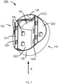
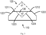
- the third mounting surface 1221 is located on a side of the first mounting surface 1211 away from the second mounting surface 1212 and obliquely extends from a first edge of the first mounting surface 1211 in a direction toward the first surface 110
- the fourth mounting surface 1222 is located on a side of the second mounting surface 1212 away from the first mounting surface 1211 and obliquely extends from a first edge of the second mounting surface 1212 in a direction toward the first surface 110.
- the first angle ⁇ 1 and the second angle ⁇ 2 are right angles. Since the corners of most walls are at right angles, setting the angles as right angles may ensure that the mounting bracket 100 may be adapted for most wall corner mounting scenarios. It will be appreciated that where the angle of the wall corner is a non-right angle, the first angle ⁇ 1 and the second angle ⁇ 2 may also be other angles matching the angle of the wall corner.
- the mounting bracket 100 may further comprise a removable first sidewall portion 130 (see FIG. 2 and FIG. 3 ) that extends from an edge of the second mounting region to a position aligned with the first mounting region.
- the first sidewall portion 130 extends from edges of both sides of the fifth mounting surface 1223 and the sixth mounting surface 1224 to a position aligned with the first mounting surface 1211 and the second mounting surface 1212.
- the first sidewall portion 130 may also extend from an edge of the third mounting surface 1221 and/or an edge of the fourth mounting surface 1222 to a position aligned with the first mounting surface 1211 and the second mounting surface 1212.
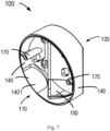
- a portion of sidewall 1401 of the second sidewall portion 140 can be removed upon mounting conductor wires or wire conduits 300 to the motion sensor 200 or to the device to be mounted.
- the motion sensor 200 or device to be mounted may need to be connected to a utility grid or other power source through conductor wires or wire conduits 300.
- the portion of side wall 1401 of the second sidewall portion 140 may be set removable, e.g., the removable sidewall 1401 may be set thinner than other portions of the second sidewall portion 140, or may be made of a breakable material.
- the second sub-regions of the second mounting region are provided with an opening 150 to enable the conductor wires or wire conduits 300 to pass through the mounting bracket 100 from a side of the second surface 120 to a side of the first surface 110.
- the opening 150 may be provided in the fourth mounting surface 1223 and/or the fifth mounting surface 1224, so that the external conductor wires and wire conduits 300 can continue to connect with the motion sensor 200 or device to be mounted through the mounting bracket 100 after passing through the removable portion 1401 of the second sidewall portion 140, or connect with the motion sensor 200 or device to be mounted directly through the mounting bracket 100 without passing through the second sidewall portion 140.
- the mounting bracket 100 may be firmly engaged to the device to be mounted, for example to the base of the motion sensor 100.
- the mounting bracket 100 may be integrally formed. In this way, the mounting bracket 100 may be manufactured at a low cost and has the advantage of being robust and reliable.
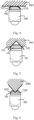
- the mounting bracket may be mounted to a variety of positions, such as corners, wall surfaces, and ceilings, by providing a variety of mounting regions on the surface of the mounting bracket, which increases the application scenarios and scope of the mounting bracket and the motion sensor or other devices engaged by the mounting bracket.
- the mounting bracket of the present disclosure may also conveniently mount conductor wires and wire conduits in multiple directions without affecting the overall appearance.
Landscapes
- Engineering & Computer Science (AREA)
- General Engineering & Computer Science (AREA)
- Mechanical Engineering (AREA)
- Casings For Electric Apparatus (AREA)
Applications Claiming Priority (1)
| Application Number | Priority Date | Filing Date | Title |
|---|---|---|---|
| CN202223544183.2U CN219829940U (zh) | 2022-12-29 | 2022-12-29 | 安装支架以及传感器组件 |
Publications (3)
| Publication Number | Publication Date |
|---|---|
| EP4394232A1 true EP4394232A1 (fr) | 2024-07-03 |
| EP4394232B1 EP4394232B1 (fr) | 2025-08-13 |
| EP4394232C0 EP4394232C0 (fr) | 2025-08-13 |
Family
ID=88274163
Family Applications (1)
| Application Number | Title | Priority Date | Filing Date |
|---|---|---|---|
| EP23307306.3A Active EP4394232B1 (fr) | 2022-12-29 | 2023-12-21 | Support de montage et ensemble capteur |
Country Status (4)
| Country | Link |
|---|---|
| EP (1) | EP4394232B1 (fr) |
| CN (1) | CN219829940U (fr) |
| AU (1) | AU2023285819B2 (fr) |
| ES (1) | ES3048933T3 (fr) |
Citations (7)
| Publication number | Priority date | Publication date | Assignee | Title |
|---|---|---|---|---|
| US1219596A (en) * | 1915-08-23 | 1917-03-20 | Manley H Simmons | Sign-holder. |
| DE9303267U1 (de) * | 1993-03-05 | 1993-06-09 | Fa. Peter Kremser, 2000 Hamburg | Befestigungssockel für eine Lampe o.dgl. |
| WO1999044472A1 (fr) * | 1998-03-03 | 1999-09-10 | Sensormatic Electronics Corporation | Support de montage pour socle de camera |
| JP2001238101A (ja) * | 2000-02-22 | 2001-08-31 | Elbex Video Ltd | テレビカメラ |
| GB2384520A (en) * | 2002-01-28 | 2003-07-30 | Everspring Ind Co Ltd | A corner fastening device |
| US20060237603A1 (en) * | 2005-04-11 | 2006-10-26 | Qingdao Minmetals And Machinery, Inc. | Appliance support assembly |
| CN201706162U (zh) * | 2010-08-20 | 2011-01-12 | 河南省电力公司漯河供电公司 | 一种壁装视频监控摄像头支架 |
-
2022
- 2022-12-29 CN CN202223544183.2U patent/CN219829940U/zh active Active
-
2023
- 2023-12-20 AU AU2023285819A patent/AU2023285819B2/en active Active
- 2023-12-21 ES ES23307306T patent/ES3048933T3/es active Active
- 2023-12-21 EP EP23307306.3A patent/EP4394232B1/fr active Active
Patent Citations (7)
| Publication number | Priority date | Publication date | Assignee | Title |
|---|---|---|---|---|
| US1219596A (en) * | 1915-08-23 | 1917-03-20 | Manley H Simmons | Sign-holder. |
| DE9303267U1 (de) * | 1993-03-05 | 1993-06-09 | Fa. Peter Kremser, 2000 Hamburg | Befestigungssockel für eine Lampe o.dgl. |
| WO1999044472A1 (fr) * | 1998-03-03 | 1999-09-10 | Sensormatic Electronics Corporation | Support de montage pour socle de camera |
| JP2001238101A (ja) * | 2000-02-22 | 2001-08-31 | Elbex Video Ltd | テレビカメラ |
| GB2384520A (en) * | 2002-01-28 | 2003-07-30 | Everspring Ind Co Ltd | A corner fastening device |
| US20060237603A1 (en) * | 2005-04-11 | 2006-10-26 | Qingdao Minmetals And Machinery, Inc. | Appliance support assembly |
| CN201706162U (zh) * | 2010-08-20 | 2011-01-12 | 河南省电力公司漯河供电公司 | 一种壁装视频监控摄像头支架 |
Also Published As
| Publication number | Publication date |
|---|---|
| EP4394232B1 (fr) | 2025-08-13 |
| CN219829940U (zh) | 2023-10-13 |
| EP4394232C0 (fr) | 2025-08-13 |
| AU2023285819A1 (en) | 2024-07-18 |
| ES3048933T3 (en) | 2025-12-12 |
| AU2023285819B2 (en) | 2025-07-17 |
Similar Documents
| Publication | Publication Date | Title |
|---|---|---|
| US20230318274A1 (en) | Weatherproof electrical enclosure with reinforcement | |
| US6164475A (en) | Electrical box for fan or fixture support | |
| US6825414B2 (en) | Exterior mounting block for electrical fixtures | |
| JPH0923534A (ja) | 天井ファン取付配線箱 | |
| JP7610670B2 (ja) | 間仕切装置 | |
| EP4394232B1 (fr) | Support de montage et ensemble capteur | |
| JP2021197234A (ja) | 照明装置 | |
| KR20060101738A (ko) | 배선용 덕트의 접속 구조 | |
| CN217064255U (zh) | 电控盒及空调器 | |
| JP2021197357A (ja) | 照明装置 | |
| JP3040257U (ja) | 照明装置 | |
| JP3470187B2 (ja) | アウトレットボックス取付け具 | |
| JP2521117Y2 (ja) | 空調配管カバー | |
| JP7787017B2 (ja) | 警報器用の取付ベース | |
| JPH0628917U (ja) | レンズとエクステンションとの取付構造 | |
| JP2013087601A (ja) | 浴室構造 | |
| KR200220988Y1 (ko) | 설치성을 향상시킨 에어컨 바디 | |
| JP3129161U (ja) | 配管用化粧カバー | |
| JPS6310588Y2 (fr) | ||
| JP2006321636A (ja) | エレベータかご室の壁の固定構造 | |
| JPH041241Y2 (fr) | ||
| JP6832733B2 (ja) | 車両の荷室内における照明装置の取付構造 | |
| JPS6345629Y2 (fr) | ||
| JPH0541571Y2 (fr) | ||
| JPS641697Y2 (fr) |
Legal Events
| Date | Code | Title | Description |
|---|---|---|---|
| PUAI | Public reference made under article 153(3) epc to a published international application that has entered the european phase |
Free format text: ORIGINAL CODE: 0009012 |
|
| STAA | Information on the status of an ep patent application or granted ep patent |
Free format text: STATUS: THE APPLICATION HAS BEEN PUBLISHED |
|
| AK | Designated contracting states |
Kind code of ref document: A1 Designated state(s): AL AT BE BG CH CY CZ DE DK EE ES FI FR GB GR HR HU IE IS IT LI LT LU LV MC ME MK MT NL NO PL PT RO RS SE SI SK SM TR |
|
| STAA | Information on the status of an ep patent application or granted ep patent |
Free format text: STATUS: REQUEST FOR EXAMINATION WAS MADE |
|
| 17P | Request for examination filed |
Effective date: 20250103 |
|
| GRAP | Despatch of communication of intention to grant a patent |
Free format text: ORIGINAL CODE: EPIDOSNIGR1 |
|
| STAA | Information on the status of an ep patent application or granted ep patent |
Free format text: STATUS: GRANT OF PATENT IS INTENDED |
|
| INTG | Intention to grant announced |
Effective date: 20250408 |
|
| GRAS | Grant fee paid |
Free format text: ORIGINAL CODE: EPIDOSNIGR3 |
|
| GRAA | (expected) grant |
Free format text: ORIGINAL CODE: 0009210 |
|
| STAA | Information on the status of an ep patent application or granted ep patent |
Free format text: STATUS: THE PATENT HAS BEEN GRANTED |
|
| AK | Designated contracting states |
Kind code of ref document: B1 Designated state(s): AL AT BE BG CH CY CZ DE DK EE ES FI FR GB GR HR HU IE IS IT LI LT LU LV MC ME MK MT NL NO PL PT RO RS SE SI SK SM TR |
|
| REG | Reference to a national code |
Ref country code: GB Ref legal event code: FG4D |
|
| REG | Reference to a national code |
Ref country code: CH Ref legal event code: EP |
|
| REG | Reference to a national code |
Ref country code: IE Ref legal event code: FG4D |
|
| U01 | Request for unitary effect filed |
Effective date: 20250813 |
|
| U07 | Unitary effect registered |
Designated state(s): AT BE BG DE DK EE FI FR IT LT LU LV MT NL PT RO SE SI Effective date: 20250820 |
|
| REG | Reference to a national code |
Ref country code: ES Ref legal event code: FG2A Ref document number: 3048933 Country of ref document: ES Kind code of ref document: T3 Effective date: 20251212 |
|
| PG25 | Lapsed in a contracting state [announced via postgrant information from national office to epo] |
Ref country code: IS Free format text: LAPSE BECAUSE OF FAILURE TO SUBMIT A TRANSLATION OF THE DESCRIPTION OR TO PAY THE FEE WITHIN THE PRESCRIBED TIME-LIMIT Effective date: 20251213 |
|
| PG25 | Lapsed in a contracting state [announced via postgrant information from national office to epo] |
Ref country code: NO Free format text: LAPSE BECAUSE OF FAILURE TO SUBMIT A TRANSLATION OF THE DESCRIPTION OR TO PAY THE FEE WITHIN THE PRESCRIBED TIME-LIMIT Effective date: 20251113 |
|
| PG25 | Lapsed in a contracting state [announced via postgrant information from national office to epo] |
Ref country code: HR Free format text: LAPSE BECAUSE OF FAILURE TO SUBMIT A TRANSLATION OF THE DESCRIPTION OR TO PAY THE FEE WITHIN THE PRESCRIBED TIME-LIMIT Effective date: 20250813 |
|
| PG25 | Lapsed in a contracting state [announced via postgrant information from national office to epo] |
Ref country code: GR Free format text: LAPSE BECAUSE OF FAILURE TO SUBMIT A TRANSLATION OF THE DESCRIPTION OR TO PAY THE FEE WITHIN THE PRESCRIBED TIME-LIMIT Effective date: 20251114 |
|
| PG25 | Lapsed in a contracting state [announced via postgrant information from national office to epo] |
Ref country code: PL Free format text: LAPSE BECAUSE OF FAILURE TO SUBMIT A TRANSLATION OF THE DESCRIPTION OR TO PAY THE FEE WITHIN THE PRESCRIBED TIME-LIMIT Effective date: 20250813 |
|
| PG25 | Lapsed in a contracting state [announced via postgrant information from national office to epo] |
Ref country code: RS Free format text: LAPSE BECAUSE OF FAILURE TO SUBMIT A TRANSLATION OF THE DESCRIPTION OR TO PAY THE FEE WITHIN THE PRESCRIBED TIME-LIMIT Effective date: 20251113 |
|
| U20 | Renewal fee for the european patent with unitary effect paid |
Year of fee payment: 3 Effective date: 20251223 |
|
| PG25 | Lapsed in a contracting state [announced via postgrant information from national office to epo] |
Ref country code: SM Free format text: LAPSE BECAUSE OF FAILURE TO SUBMIT A TRANSLATION OF THE DESCRIPTION OR TO PAY THE FEE WITHIN THE PRESCRIBED TIME-LIMIT Effective date: 20250813 |
|
| PG25 | Lapsed in a contracting state [announced via postgrant information from national office to epo] |
Ref country code: CZ Free format text: LAPSE BECAUSE OF FAILURE TO SUBMIT A TRANSLATION OF THE DESCRIPTION OR TO PAY THE FEE WITHIN THE PRESCRIBED TIME-LIMIT Effective date: 20250813 |
|
| PG25 | Lapsed in a contracting state [announced via postgrant information from national office to epo] |
Ref country code: SK Free format text: LAPSE BECAUSE OF FAILURE TO SUBMIT A TRANSLATION OF THE DESCRIPTION OR TO PAY THE FEE WITHIN THE PRESCRIBED TIME-LIMIT Effective date: 20250813 |