EP4394330A1 - Détection d'un déplacement linéaire avec un aimant incliné - Google Patents
Détection d'un déplacement linéaire avec un aimant incliné Download PDFInfo
- Publication number
- EP4394330A1 EP4394330A1 EP22217272.8A EP22217272A EP4394330A1 EP 4394330 A1 EP4394330 A1 EP 4394330A1 EP 22217272 A EP22217272 A EP 22217272A EP 4394330 A1 EP4394330 A1 EP 4394330A1
- Authority
- EP
- European Patent Office
- Prior art keywords
- magnet
- sensor
- displacement
- along
- magnetic field
- Prior art date
- Legal status (The legal status is an assumption and is not a legal conclusion. Google has not performed a legal analysis and makes no representation as to the accuracy of the status listed.)
- Pending
Links
Images


Classifications
-
- G—PHYSICS
- G01—MEASURING; TESTING
- G01D—MEASURING NOT SPECIALLY ADAPTED FOR A SPECIFIC VARIABLE; ARRANGEMENTS FOR MEASURING TWO OR MORE VARIABLES NOT COVERED IN A SINGLE OTHER SUBCLASS; TARIFF METERING APPARATUS; MEASURING OR TESTING NOT OTHERWISE PROVIDED FOR
- G01D5/00—Mechanical means for transferring the output of a sensing member; Means for converting the output of a sensing member to another variable where the form or nature of the sensing member does not constrain the means for converting; Transducers not specially adapted for a specific variable
- G01D5/12—Mechanical means for transferring the output of a sensing member; Means for converting the output of a sensing member to another variable where the form or nature of the sensing member does not constrain the means for converting; Transducers not specially adapted for a specific variable using electric or magnetic means
- G01D5/14—Mechanical means for transferring the output of a sensing member; Means for converting the output of a sensing member to another variable where the form or nature of the sensing member does not constrain the means for converting; Transducers not specially adapted for a specific variable using electric or magnetic means influencing the magnitude of a current or voltage
- G01D5/142—Mechanical means for transferring the output of a sensing member; Means for converting the output of a sensing member to another variable where the form or nature of the sensing member does not constrain the means for converting; Transducers not specially adapted for a specific variable using electric or magnetic means influencing the magnitude of a current or voltage using Hall-effect devices
- G01D5/145—Mechanical means for transferring the output of a sensing member; Means for converting the output of a sensing member to another variable where the form or nature of the sensing member does not constrain the means for converting; Transducers not specially adapted for a specific variable using electric or magnetic means influencing the magnitude of a current or voltage using Hall-effect devices influenced by the relative movement between the Hall device and magnetic fields
-
- G—PHYSICS
- G01—MEASURING; TESTING
- G01B—MEASURING LENGTH, THICKNESS OR SIMILAR LINEAR DIMENSIONS; MEASURING ANGLES; MEASURING AREAS; MEASURING IRREGULARITIES OF SURFACES OR CONTOURS
- G01B7/00—Measuring arrangements characterised by the use of electric or magnetic techniques
- G01B7/02—Measuring arrangements characterised by the use of electric or magnetic techniques for measuring length, width or thickness
-
- G—PHYSICS
- G01—MEASURING; TESTING
- G01D—MEASURING NOT SPECIALLY ADAPTED FOR A SPECIFIC VARIABLE; ARRANGEMENTS FOR MEASURING TWO OR MORE VARIABLES NOT COVERED IN A SINGLE OTHER SUBCLASS; TARIFF METERING APPARATUS; MEASURING OR TESTING NOT OTHERWISE PROVIDED FOR
- G01D5/00—Mechanical means for transferring the output of a sensing member; Means for converting the output of a sensing member to another variable where the form or nature of the sensing member does not constrain the means for converting; Transducers not specially adapted for a specific variable
- G01D5/12—Mechanical means for transferring the output of a sensing member; Means for converting the output of a sensing member to another variable where the form or nature of the sensing member does not constrain the means for converting; Transducers not specially adapted for a specific variable using electric or magnetic means
- G01D5/14—Mechanical means for transferring the output of a sensing member; Means for converting the output of a sensing member to another variable where the form or nature of the sensing member does not constrain the means for converting; Transducers not specially adapted for a specific variable using electric or magnetic means influencing the magnitude of a current or voltage
- G01D5/16—Mechanical means for transferring the output of a sensing member; Means for converting the output of a sensing member to another variable where the form or nature of the sensing member does not constrain the means for converting; Transducers not specially adapted for a specific variable using electric or magnetic means influencing the magnitude of a current or voltage by varying resistance
Definitions
- the present invention relates to systems for magnetically sensing a displacement of a target, and in particular to such systems for sensing a displacement of a magnet relative to a sensor.
- FIG 1 An example of a standard implementation is depicted in FIG 1 , showing a magnet 40 (e.g. a bar magnet) above a sensor 20 sensitive to the magnetic field produced by the magnet 40.
- the magnet 40 is magnetized along its longitudinal direction, which is also parallel to the displacement d to be sensed. As the magnet 40 moves along the displacement direction d, the magnetic field measured by the sensor 20 changes and this change can be related to the displacement d of the magnet 40.
- the maximum displacement which can be sensed in this way is limited. Indeed, the maximum displacement is constrained by the length (longitudinal dimension) of the magnet; typically being about the same order as the length. However, simply increasing the size of the magnet spreads out the magnetic field and thus entails that the field varies more slowly over a given distance, thereby impacting the resolution (or accuracy) that the sensor can achieved. For a typical traditional sensor (which measures the magnetic field in one sensing region), the maximum displacement which can in practice be sensed is therefore limited to about 20-30 mm.
- a differential sensor (as depicted in FIG 1 ), which measures the magnetic field in two sensing regions and yields an output based on the difference between the measurements in these regions. This is useful to achieve a certain immunity against stray magnetic fields, but relies on a (prominent) gradient in the magnetic field and is thus more impact by a dilution of the magnetic field. Accordingly, a typical differential sensor may be well-suited for sensing a displacement of 20 mm or below, but may not be practicable for longer displacements (e.g. 30 mm or higher).
- the magnetization direction is substantially perpendicular to a major surface (e.g. two major surfaces) of the magnet. It is a further advantage of embodiments of the present invention that the magnet can have a comparatively simple and conventional design. It is yet a further advantage of embodiments of the present invention that the magnet may be easy to procure and/or manufacture.
- the senor may be a differential sensor. It is a further advantage of embodiments of the present invention that the sensor may be relatively immune to stray magnetic fields.
- the sensed displacement may be due to a movement of the magnet or of the sensor or both.
- the present invention relates to a system for sensing a displacement along a direction y of a magnet relative to a sensor, comprising: (i) a sensor for measuring a first magnetic field component B u along a direction u, and a second magnetic field component B z along a direction z, substantially orthogonal to u and y ; and (ii) a magnet above the sensor in the z -direction, the magnet having a magnetization direction substantially perpendicular to a major surface of the magnet, substantially perpendicular to the z -direction and different from the y -direction.
- the present invention relates to a use of a system according to any embodiment of the first aspect, for sensing a displacement along the direction y of the magnet relative to the sensor.
- top, bottom, over, under and the like in the description and the claims are used for descriptive purposes and not necessarily for describing relative positions. It is to be understood that the terms so used are interchangeable with their antonyms under appropriate circumstances and that the embodiments of the invention described herein are capable of operation in other orientations than described or illustrated herein.
- an element described herein of an apparatus embodiment is an example of a means for carrying out the function performed by the element for the purpose of carrying out the invention.
- the present invention relates to a system for sensing a displacement along a direction y of a magnet relative to a sensor, comprising: (i) a sensor for measuring a first magnetic field component B u along a direction u, and a second magnetic field component B z along a direction z, substantially orthogonal to u and y ; and (ii) a magnet above the sensor in the z -direction, the magnet having a magnetization direction substantially perpendicular to a major surface of the magnet, substantially perpendicular to the z -direction and different from the y -direction.
- the magnetization direction being substantially perpendicular to a major surface (e.g. a major face) of the magnet may comprise the major surface having a surface area of at least 15% of the total surface area of the magnet; preferably at least 20%, more preferably at least 25%, still more preferably at least 30%, most preferably at least 35%, such as at least 40% or at least 45%.
- the major surface may be substantially planar.
- the magnetization direction may be substantially perpendicular to two major surfaces (e.g. two substantially parallel surfaces) of the magnet.
- the magnetization direction may be perpendicular to a longitudinal direction of the magnet.
- the longitudinal direction may be the length or the height, preferably the length.
- each of the sensors may also comprise distinct sensing elements for determining the magnetic field components in the u- and z -direction.
- these sensing elements may not measure at the same point/spot in space but at two points/spots separated by a short distance (typically in the same order of magnitude as the size of the sensing elements, i.e. tens to hundreds of micron; for example between 10 and 200 ⁇ m, e.g. between 30 and 100 ⁇ m).
- the sensing region is a region (e.g. a 1D or 2D area) defined by and comprising these sensing points or spots.
- the sensor-or (each of the) sensing unit(s)-may comprise sensing elements which do not measure B u (e.g. B u ,1 and/or B u ,2 ) and B z (e.g. B z ,1 and/or B z ,2 ) directly.
- it may for example comprise sensing elements which measure two other magnetic field components (e.g. B x and B y ) which can be combined into the field component of interest (e.g. B u ).
- it may be made up of two distinct sensing elements but having both a maximum axis of sensitivity parallel to the z -direction (e.g. horizontal hall elements), together with a magnetic concentrator (e.g.
- the system may be (used as) a magnetic position sensor.
- any feature of any embodiment of the first aspect may independently be as correspondingly described for any embodiment of any of the other aspects.
- the magnet may move-relative to the sensor-substantially parallel to the y -direction. In other embodiments, the magnet may move-relative to the sensor-at angle with the y -direction. Notwithstanding, also in the latter embodiments the displacement along the y -direction may be sensed. In embodiments, the magnet may move substantially linearly. In embodiments, the sensed displacement may be a linear displacement.
- step b may comprise determining the displacement of the magnet from B u ,1 , B u ,2 , B z ,1 , and B z ,2 . In embodiments, step b may further comprise calculating a difference d B u between B u ,1 and B u ,2 and a difference d B z between B z ,1 and B z ,2 .
- dB u may be calculated form k u ( B u ,1 - B u ,2 ) and/or dB z may be calculated from k z ( B z ,1 - B z ,2 ), wherein k u and k z are correction factors.
- the determined displacement may be related to dB u du 1 dB z du 2 .
- du 1 is the distance between the two sensing spots at which the magnetic field component B u ,1 and the magnetic field component B u ,2 are measured
- du 2 is the distance between the two sensing spots at which the magnetic field component B z ,1 and the magnetic field component B z ,2 are measured.
- the first and second sensing units-and thus the first and second sensing region- are typically separated from each other by a predetermined distance (typically in the order of mm, such as from 1 mm to 5 mm, preferably from 1.5 mm to 2.5 mm, e.g. 2 mm) along the u-direction.
- an aspect ratio of the sensing region spacing (e.g. du 1 , du 2 and/or du ) to magnet width (spacing:width) may be from 1:0.5 to 1:5, preferably from 1:1 to 3:1.
- the displacement determined in step b may more specifically be related to atan2( B z , B u ) or atan 2 dB z du 1 dB u du 2 , wherein atan2( y , x ) is a function which modifies the arctangent atan( y / x ) based on the signs of x and y (i.e. based on a form of quadrant detection) so that the range of the function becomes [0°, 360°]. Note that the choice of which term to use as x and which as y (i.e.
- the position determined in step b may likewise be related to atan2(- y , x ) atan2(x,y) or atan2(- x , y ).
- the lookup table could be based on any of B u or B z -or dB u / du 1 and dB z / du 2 -as such, the ratio of both or the atan2 of both.
- Using the ratio (or the atan2, which uses said ratio indirectly) may be advantageous in that it can reduces or cancels out certain influences (e.g. temperature) which impact the numerator and denominator proportionally.
- any feature of any embodiment of the second aspect may independently be as correspondingly described for any embodiment of any of the other aspects.
- the present invention relates to a use of a system according to any embodiment of the first aspect, for sensing a displacement along the direction y of the magnet relative to the sensor.
- any feature of any embodiment of the third aspect may independently be as correspondingly described for any embodiment of any of the other aspects.
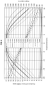
- FIG 4-FIG 7 The setup for the simulations was as schematically shown in FIG 2 and FIG 3 .
- the simulations used a bar magnet magnetized along its width and having a length of 50 mm, width of 2 mm and height of 10 mm; an air gap (along z ) of 4 mm; a displacement (along y ) of up to 40 mm (i.e. -20 mm to +20 mm); and an equivalent stroke (along x ) of up to 10 mm.
- results depicted in FIG 4-FIG 7 are each time based on a differential sensor (as also shown in FIG 2 -with thus the angular output and/or displacement obtained based on ratio including dB u and dB z ), but the same simulations were also made using a traditional sensor using only one sensing region (with the angular output and/or displacement obtained based on B u / B z ) and these yielded comparable results.
- the common mode error represents the maximum measurement error over a temperature range of -40 to 160 °C induced by the common-mode magnetic field of the magnet and the sensitivity mismatch between the sensing units in absence of further calibration.
- This error can be reduced by temperature calibration (e.g. temperature calibration of the magnetic sensitivities and/or temperature calibration of the angular output).
- the mm-values expressed in the legend of FIG 4 correspond to half of the equivalent stroke (i.e. d '/2).
- a change in equivalent stroke here essentially corresponds to a change in the angle ⁇ between the magnet's magnetization direction and the y -direction (i.e. a change in the degree of 'leaning' of the magnet).
- the 'lean angle' i.e. 90°- ⁇
- equivalent stroke d' is related to the y -displacement d and equivalent stroke d' as: atan2( d, d ') .
- the simulated results reveal over the whole investigated range an angular output representative of the linear displacement with a good default linearity, a gradient which is sufficiently large (i.e. typically > 6 mT/mm) and a CMRR which remains small.
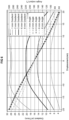
- FIG 5 showing the simulated results of the effect of the magnet height on the gradient, angular output and CMRR.
- the simulated results mainly indicate a moderate effect of the magnet height on the useful gradient strength. Notwithstanding, even if the height is reduced to 5 mm, the gradient strength nevertheless remains good at > 6 mT/mm over the full displacement. Alongside the effect on the gradient strength, more subdued effects on the angle range (slightly larger for smaller height) and CMRR (slightly smaller for smaller height) are also observed.
- a magnet height of 5 mm (rather than the default of 10 mm up to now) was used.
- the width has a considerable impact on the useful gradient: the gradient strength decreases with lower width and stops increasing above a certain width. Together with the change in the gradient strength, the linearity of the angular output also drops for higher thicknesses. These thus indicate that the width may ideally be relatively thin (e.g. compared to the length, and/or to the spacing between the sensing elements).
- FIG 7 showing the simulated results of the effect of the air gap on the gradient and angular output.
- the air gap was moreover investigated in a broader range of 3 mm to 10 mm.
- a fairly pronounced effect of the air gap could be observed, with larger air gaps having a weaker gradient and lower linearity of the angular output.
- the gradient and angle change only by about 0.6%.
- an angular output with a good default linearity and a good gradient strength are obtained over a wide range of air gaps.
- the setup was again akin to the one schematically depicted in FIG 2 and FIG 3 , with a bar magnet magnetized along its width and having a length of 40 mm, width of 1 mm and height of 12 mm.
- the measurement was performed with the sensor on an XYZ movement stage, which moved a Melexis stray field immune Triaxis ® sensor from outside to underneath the magnet over a total displacement (along the y -direction) of 24 mm (which was the limit of the XYZ movement stage).
- the magnet was held fixed in a configuration such that it magnetization direction was angled by about 80° with respect to the displacement direction, which allowed to transfer the 24 mm displacement into an effective stroke (along the x-direction) of a few millimetres.
Landscapes
- Physics & Mathematics (AREA)
- General Physics & Mathematics (AREA)
- Transmission And Conversion Of Sensor Element Output (AREA)
Priority Applications (3)
| Application Number | Priority Date | Filing Date | Title |
|---|---|---|---|
| EP22217272.8A EP4394330A1 (fr) | 2022-12-30 | 2022-12-30 | Détection d'un déplacement linéaire avec un aimant incliné |
| US18/396,113 US12566080B2 (en) | 2022-12-30 | 2023-12-26 | Sensing a linear displacement with a leaning magnet |
| CN202311861279.8A CN118274694A (zh) | 2022-12-30 | 2023-12-29 | 使用倾斜磁体感测线性位移 |
Applications Claiming Priority (1)
| Application Number | Priority Date | Filing Date | Title |
|---|---|---|---|
| EP22217272.8A EP4394330A1 (fr) | 2022-12-30 | 2022-12-30 | Détection d'un déplacement linéaire avec un aimant incliné |
Publications (1)
| Publication Number | Publication Date |
|---|---|
| EP4394330A1 true EP4394330A1 (fr) | 2024-07-03 |
Family
ID=84767226
Family Applications (1)
| Application Number | Title | Priority Date | Filing Date |
|---|---|---|---|
| EP22217272.8A Pending EP4394330A1 (fr) | 2022-12-30 | 2022-12-30 | Détection d'un déplacement linéaire avec un aimant incliné |
Country Status (3)
| Country | Link |
|---|---|
| US (1) | US12566080B2 (fr) |
| EP (1) | EP4394330A1 (fr) |
| CN (1) | CN118274694A (fr) |
Citations (3)
| Publication number | Priority date | Publication date | Assignee | Title |
|---|---|---|---|---|
| JPH06229708A (ja) * | 1993-02-05 | 1994-08-19 | Hamamatsu Koden Kk | 無接触式直線変位センサ |
| US20110133725A1 (en) * | 2009-12-04 | 2011-06-09 | Werner Dengler | Hall-type linear-travel sensor for intermediate travel |
| US20190368903A1 (en) * | 2018-05-30 | 2019-12-05 | Rockwell Automation Technologies, Inc. | Encoder System for Position Determination with Inclined Scale |
Family Cites Families (2)
| Publication number | Priority date | Publication date | Assignee | Title |
|---|---|---|---|---|
| EP1252481A1 (fr) * | 2000-01-13 | 2002-10-30 | Continental Teves AG & Co. oHG | Capteur de deplacement lineaire et utilisation en tant que dispositif d'actionnement de vehicules motorises |
| JP4589410B2 (ja) * | 2005-12-16 | 2010-12-01 | 旭化成エレクトロニクス株式会社 | 位置検出装置 |
-
2022
- 2022-12-30 EP EP22217272.8A patent/EP4394330A1/fr active Pending
-
2023
- 2023-12-26 US US18/396,113 patent/US12566080B2/en active Active
- 2023-12-29 CN CN202311861279.8A patent/CN118274694A/zh active Pending
Patent Citations (3)
| Publication number | Priority date | Publication date | Assignee | Title |
|---|---|---|---|---|
| JPH06229708A (ja) * | 1993-02-05 | 1994-08-19 | Hamamatsu Koden Kk | 無接触式直線変位センサ |
| US20110133725A1 (en) * | 2009-12-04 | 2011-06-09 | Werner Dengler | Hall-type linear-travel sensor for intermediate travel |
| US20190368903A1 (en) * | 2018-05-30 | 2019-12-05 | Rockwell Automation Technologies, Inc. | Encoder System for Position Determination with Inclined Scale |
Also Published As
| Publication number | Publication date |
|---|---|
| CN118274694A (zh) | 2024-07-02 |
| US12566080B2 (en) | 2026-03-03 |
| US20240219207A1 (en) | 2024-07-04 |
Similar Documents
| Publication | Publication Date | Title |
|---|---|---|
| EP3006896B1 (fr) | Boussole numérique à trois axes | |
| JP6043721B2 (ja) | 改良型位置センサ | |
| CN102449506B (zh) | 磁性定位方法和结构 | |
| CN103323795B (zh) | 一体式三轴磁传感器 | |
| Yang et al. | Binocular vision-based method used for determining the static and dynamic parameters of the long-stroke shakers in low-frequency vibration calibration | |
| CN103116144B (zh) | 一种采用磁变轨结构的z向磁场传感器 | |
| CN100588983C (zh) | 小型永磁体空间磁场的三维测量装置及其测量方法 | |
| EP2581707B1 (fr) | Capteur de position linéaire magnétique sans contact | |
| CN108717169B (zh) | 一种二维磁场传感器 | |
| CN107421525A (zh) | 一种隧道磁阻非谐振式三轴mems陀螺 | |
| CN115560659A (zh) | 差分电容位移传感器的标定方法 | |
| CN116736199A (zh) | 一种空间静态磁场分布测量系统及方法 | |
| CN102620724B (zh) | 地磁传感器装置以及数字罗盘 | |
| US12117315B2 (en) | Magnetic position sensor system | |
| US12140647B2 (en) | Position sensor system, optical lens system and display | |
| EP4394330A1 (fr) | Détection d'un déplacement linéaire avec un aimant incliné | |
| WO2018199067A1 (fr) | Capteur magnétique | |
| CN106771360B (zh) | 一种单轴mems加速度计 | |
| CN207395752U (zh) | 一种隧道磁阻检测的微惯性组件 | |
| CN106443069B (zh) | 一种基于各向异性磁电阻效应的差分式单轴mems加速度计 | |
| CN106338618B (zh) | 一种基于巨磁电阻效应的单轴mems加速度计 | |
| CN207197533U (zh) | 一种隧道磁阻非谐振式三轴mems陀螺 | |
| CN106501547B (zh) | 一种基于巨磁电阻效应的差分式单轴mems加速度计 | |
| CN106706959B (zh) | 一种基于各向异性磁电阻效应的单轴mems加速度计 | |
| CN106771354B (zh) | 一种单轴mems加速度计 |
Legal Events
| Date | Code | Title | Description |
|---|---|---|---|
| PUAI | Public reference made under article 153(3) epc to a published international application that has entered the european phase |
Free format text: ORIGINAL CODE: 0009012 |
|
| STAA | Information on the status of an ep patent application or granted ep patent |
Free format text: STATUS: THE APPLICATION HAS BEEN PUBLISHED |
|
| AK | Designated contracting states |
Kind code of ref document: A1 Designated state(s): AL AT BE BG CH CY CZ DE DK EE ES FI FR GB GR HR HU IE IS IT LI LT LU LV MC ME MK MT NL NO PL PT RO RS SE SI SK SM TR |
|
| STAA | Information on the status of an ep patent application or granted ep patent |
Free format text: STATUS: REQUEST FOR EXAMINATION WAS MADE |
|
| 17P | Request for examination filed |
Effective date: 20250103 |
|
| GRAP | Despatch of communication of intention to grant a patent |
Free format text: ORIGINAL CODE: EPIDOSNIGR1 |
|
| STAA | Information on the status of an ep patent application or granted ep patent |
Free format text: STATUS: GRANT OF PATENT IS INTENDED |
|
| INTG | Intention to grant announced |
Effective date: 20260213 |