EP4394436A1 - Radarleistungskalibrierung mit fehlanpassungskompensation - Google Patents
Radarleistungskalibrierung mit fehlanpassungskompensation Download PDFInfo
- Publication number
- EP4394436A1 EP4394436A1 EP22307072.3A EP22307072A EP4394436A1 EP 4394436 A1 EP4394436 A1 EP 4394436A1 EP 22307072 A EP22307072 A EP 22307072A EP 4394436 A1 EP4394436 A1 EP 4394436A1
- Authority
- EP
- European Patent Office
- Prior art keywords
- output
- signal
- power
- detector
- power amplifier
- Prior art date
- Legal status (The legal status is an assumption and is not a legal conclusion. Google has not performed a legal analysis and makes no representation as to the accuracy of the status listed.)
- Pending
Links
Images



Classifications
-
- G—PHYSICS
- G01—MEASURING; TESTING
- G01S—RADIO DIRECTION-FINDING; RADIO NAVIGATION; DETERMINING DISTANCE OR VELOCITY BY USE OF RADIO WAVES; LOCATING OR PRESENCE-DETECTING BY USE OF THE REFLECTION OR RERADIATION OF RADIO WAVES; ANALOGOUS ARRANGEMENTS USING OTHER WAVES
- G01S13/00—Systems using the reflection or reradiation of radio waves, e.g. radar systems; Analogous systems using reflection or reradiation of waves whose nature or wavelength is irrelevant or unspecified
- G01S13/88—Radar or analogous systems specially adapted for specific applications
- G01S13/93—Radar or analogous systems specially adapted for specific applications for anti-collision purposes
- G01S13/931—Radar or analogous systems specially adapted for specific applications for anti-collision purposes of land vehicles
-
- G—PHYSICS
- G01—MEASURING; TESTING
- G01R—MEASURING ELECTRIC VARIABLES; MEASURING MAGNETIC VARIABLES
- G01R35/00—Testing or calibrating of apparatus covered by the other groups of this subclass
- G01R35/005—Calibrating; Standards or reference devices, e.g. voltage or resistance standards, "golden" references
-
- G—PHYSICS
- G01—MEASURING; TESTING
- G01R—MEASURING ELECTRIC VARIABLES; MEASURING MAGNETIC VARIABLES
- G01R21/00—Arrangements for measuring electric power or power factor
-
- G—PHYSICS
- G01—MEASURING; TESTING
- G01S—RADIO DIRECTION-FINDING; RADIO NAVIGATION; DETERMINING DISTANCE OR VELOCITY BY USE OF RADIO WAVES; LOCATING OR PRESENCE-DETECTING BY USE OF THE REFLECTION OR RERADIATION OF RADIO WAVES; ANALOGOUS ARRANGEMENTS USING OTHER WAVES
- G01S7/00—Details of systems according to groups G01S13/00, G01S15/00, G01S17/00
- G01S7/02—Details of systems according to groups G01S13/00, G01S15/00, G01S17/00 of systems according to group G01S13/00
- G01S7/40—Means for monitoring or calibrating
- G01S7/4004—Means for monitoring or calibrating of parts of a radar system
- G01S7/4008—Means for monitoring or calibrating of parts of a radar system of transmitters
- G01S7/4013—Means for monitoring or calibrating of parts of a radar system of transmitters involving adjustment of the transmitted power
-
- G—PHYSICS
- G01—MEASURING; TESTING
- G01S—RADIO DIRECTION-FINDING; RADIO NAVIGATION; DETERMINING DISTANCE OR VELOCITY BY USE OF RADIO WAVES; LOCATING OR PRESENCE-DETECTING BY USE OF THE REFLECTION OR RERADIATION OF RADIO WAVES; ANALOGOUS ARRANGEMENTS USING OTHER WAVES
- G01S7/00—Details of systems according to groups G01S13/00, G01S15/00, G01S17/00
- G01S7/02—Details of systems according to groups G01S13/00, G01S15/00, G01S17/00 of systems according to group G01S13/00
- G01S7/40—Means for monitoring or calibrating
- G01S7/4004—Means for monitoring or calibrating of parts of a radar system
- G01S7/4021—Means for monitoring or calibrating of parts of a radar system of receivers
Definitions
- a radar system transmits an electromagnetic signal and receives back reflections of the transmitted signal.
- the time delay between the transmitted and received signals can be determined and used to calculate the distance and/or the speed of objects causing the reflections.
- radar systems can be used to determine the distance and/or the speed of oncoming vehicles and other obstacles.
- a typical calibration procedure can involve several stages of electronic components cooperating to adjust the power level; ultimately, the goal is for the radar transmitter to emit signals at a power level as close as possible to the calibration target. Ensuring an accurate output power is very important for the radar performance and adherence to safety standards in automotive radar applications. For example, some countries restrict maximum output power to a certain level, and calibration allows the radar system to satisfy the restriction.
- the embodiments described herein provide for calibration of a radar system's transmit power to a target level at the ARP with greater accuracy by adjusting a calibration target voltage and driving the power amplifier at a correspondingly adjusted supply voltage, to compensate for mismatch between the power amplifier output and the ARP.
- Embodiments of the systems and methods herein use peak-to-peak detectors at both the coupled and the isolated outputs of a bi-directional coupler connected to the power amplifier output.
- the incident power is measured by measuring the output voltage of a connected PPD; this measurement is used to perform an initial calibration of the output power.
- the calibrated output power is supplied to the bi-directional coupler; at the isolated output, the reflected power is measured by measuring the output voltage of a connected PPD.
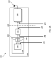
- FIGS. 1A and 1B illustrate an example vehicle radar system 100 in accordance with the present disclosure (when incorporated into a vehicle, vehicle radar system 100 may sometimes be referred to as a vehicle radar subsystem).
- Vehicle radar system 100 includes at least one radar transmitter 102, and may include additional apparatus that are not pictured, such as one or more radar receivers, controllers and control circuitry, system integration packages, and the like.
- the radar transmitter 102 may include an integrated circuit 104, such as a system-on-chip, that comprises the radar transmitter's 102 native transmission circuitry, described further below.
- the integrated circuit 104 includes a transmission signal section 140 comprising circuitry for producing a transmission signal at a controllable output power level.
- this circuitry may include a suitable microcontroller as well as suitable input and output buffers, voltage regulators, power amplifiers, couplers, peak-to-peak detectors (PPDs) and other detectors/sensors, and the like.
- the integrated circuit 104 further includes power measurement devices for measuring output power: a first measurement device 150 measures incident power; and, a second measurement device 160 measures reflected power.
- the measurement devices 150, 160 may each provide feedback signals to the transmission signal section 140 (i.e., to a microcontroller) for the purpose of performing the calibration procedures herein.
- the measurement devices 150, 160 may be any suitable sensor or detector arrangement that can be configured to measure characteristics of the output signal, such as current, voltage, etc.
- Power amplifier 206 may be the power amplifier of a vehicle radar system being calibrated (e.g., a power amplifier implemented within radar transmitter 102 of FIG. 1 ). Power amplifier 206 is configured to generate an amplified electromagnetic signal (e.g., a radar signal) that is output by power amplifier 206 as a transmitted signal. The output signal generated by power amplifier 206 is, effectively, the transmission signal; as such, a magnitude of the signal output by power amplifier 206 is the same as (or directly related to) the magnitude of the signal that will ultimately be output or transmitted by (a) transmit antenna(s) of the vehicle's radar system.
- an amplified electromagnetic signal e.g., a radar signal
- the output signal generated by power amplifier 206 is, effectively, the transmission signal; as such, a magnitude of the signal output by power amplifier 206 is the same as (or directly related to) the magnitude of the signal that will ultimately be output or transmitted by (a) transmit antenna(s) of the vehicle's radar system.
- the coupler 208 When the coupler 208 is a bi-directional coupler, the ports 284, 286 swap functionality depending on the direction of signal flow - when the signal passes from the input port 280 to the output port 282, the "coupled port” is port 284 and the “isolated port” is port 286.
- the second transmission line is coupled to the first transmission line such that a part of the signal received at the input port 280 and output at the output port 282 is also output at the coupled port 284.
- the coupler 208 may comprise at least two directional couplers connected in parallel or in series, with one of the couplers connected in alignment with the transmission signal forward propagation, and another of the couplers connected in reverse alignment (i.e., aligned with the transmission signal reverse propagation).
- the coupler 208 may also be a dual directional coupler, with both a forward-coupled port and a reverse-coupled port each terminated to an internal load.
- the coupler 208 may be implemented in any suitable manner so as to couple a portion of the differential output signal of power amplifier 206 into the power calibration mechanism of the radar transmitter 200.
- the coupler 208 may be connected at any points in the transmit signal path of power amplifier 206 to the antenna (through ARP 212) or to any other power amplifiers in which the amplifier's output power level is to be calibrated.
- An example embodiment is shown in FIG. 2 , in which a first detector is electrically connected to the coupled port 284 and is referred to herein as the "coupled detector” 220, and a second detector is electrically connected to the isolated port 286 and is referred to herein as the "isolated detector" 222.
- the detectors 220, 222 may be any suitable power sensors that produce output signals representing their corresponding power measurements, for use in the calibration procedure.
- the detectors 220, 222 may be PPDs that produce an output voltage corresponding to the input to the PPD.
- the coupled detector 220 in electrical communication with the coupled port 284 of the coupler 208 may be configured to convert the coupled portion of the output signal of power amplifier 206 to a direct-current (DC) signal having a magnitude that is equal to or proportional to, or otherwise a function of, the magnitude of the peaks of the coupled output signal 225 generated by coupler 208.
- DC direct-current
- the controller 240 may be configured to receive the amplified detector 220, 222 output signals and analyze them to determine the measured incident power and reflected power levels. Further, the controller 240 may be configured to calculate a new calibration target based on the measured power levels, and to translate the calibration target to a supply voltage adjustment as described further below.
- the controller 240 may also electrically connect to a switch (not shown) that receives the outputs of the detectors 220, 222; responsive to control signals of the controller 240, the switch may switch whether the coupled detector 220 output or the isolated detector 222 output is passed into the VGA 230.
- the controller 240 outputs control signals to control the operation of the power amplifier 206.
- a voltage regulator 250 such as a low drop-out regulator (“LDO") may be in electrical communication with one or more output ports of the controller 240, and also with one or more components of the power amplifier 206.
- the voltage regulator 250 may provide a supply voltage 255 to a gain section of the power amplifier 206.
- the voltage regulator 250 may receive the control signals from the controller 240 and may adjust the supply voltage 255 according to the control signals; the supply voltage 255 value affects the amount of voltage and/or current gain, power gain, impedance fidelity, and other characteristics of the power amplifier 206 output.
- the controller 240 may execute the control logic to determine the incident and reflected power levels, adjust the calibration target accordingly, and then control the voltage regulator 250 to output a supply voltage 255 that will cause the drivers 262, 264 and output stages 264, 268 to produce a transmission signal with calibrated output power that compensates for mismatch between the power amplifier 206 and the transition package 210 and between the transition package 210 and the transmission antennas (not shown).
- a transmitter of a radar system may perform calibration procedures to produce a transmission signal at an output power that is calibrated to optimize signal quality at the transmission antenna; accuracy of the calibration is maximized at the antenna reference plane by compensating a calibration target to account for mismatch (e.g., impedance mismatch and other causes of reflected power) in the transmission signal path.
- an example method 300 of calibrating output power may be performed by a controller, such as a microprocessor executing control logic instructions to measure input signals and generate control signals as outputs.
- the controller may obtain an output signal of a coupled detector, such as a coupled PPD as described above.
- the controller may receive an amplified output signal of a PPD coupled to the coupled port of a bi-directional coupler that receives the output signal of a power amplifier as input; the controller may determine an output voltage or output current of the coupled PPD; this value is proportional to the coupled signal, i.e., a sample of the signal on the coupler's transmission line, which in turn is proportional to the power amplifier output.
- the controller may calibrate the power amplifier output power based on the output of the coupled detector. This output represents a measurement of the incident power level; for example, the detector output voltage read by the controller may correspond to a magnitude of the output power measured approximate the power amplifier output port.
- the controller may apply any suitable calibration technique based upon the measured value and a stored calibration target.
- the stored calibration target may be an expected voltage value that the coupled PPD should produce if the output power is accurately calibrated.
- the stored calibration target may be an expected power level, and the controller may be configured to convert the received output voltage to a corresponding measured incident power level and compare it to the stored calibration target. The controller may then generate one or more control signals that cause the supply voltage to the power amplifier gain stage to be increased or decreased to bring the measured value toward the calibration target. This process is iterated until the output power is calibrated with respect to the incident power measurements.
- the controller may obtain an output signal of an isolated detector, such as an isolated PPD as described above.
- the controller may receive an amplified output signal of a PPD coupled to the isolated port of the bi-directional coupler to which the coupled PPD is coupled; the controller may determine an output voltage or output current of the isolated PPD; this value is proportional to the output signal at the coupler's isolated port, which in turn is proportional to the reflected power on one or both of the coupler's transmission lines.
- the collection (306) of the isolated PPD output occurs when the transmission signal has an output power level that has been initially calibrated (at 304) with respect to the incident power of the transmission signal. That is, in some embodiments, the reflected power of the transmission signal is measured when the output power level approximates the initial calibration target.
- the output current or output voltage of the isolated detector may not correspond to a direct measurement of the reflected power; the characteristics of the specific coupler and the specific detector must be taken into account.
- the coupling factor determines what fraction of the input signal is coupled and delivered to the coupled port (port 284 of coupler 208).
- Directivity refers to how well the coupler differentiates forward-propagating from reverse-propagating portions of the signal, provided the isolated port of the coupler is properly terminated.
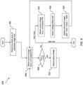
- FIG. 4 presents another example method 400 for power calibration with mismatch compensation, executed by a controller as described above.
- the controller may determine an initial calibration target that corresponds to the desired output power level of the transmission signal, measured with respect to the antenna reference plane.
- the initial value may be stored in memory of the controller.
- the calibration target value may be a target voltage, a target current, or a target signal level, in various embodiments.
- the calibration target is a target voltage (Vcal) of the output signal of a coupled PPD as described above.
- FIGS. 5A and 5B are provided to demonstrate the efficacy of the present systems and methods of calibrating output power of a radar transmitter.
- the charts 500, 510 illustrate results of the following simulation: first, the output of the coupled PPD was calibrated with a constant initial calibration target Vcal of 112mV (equivalent to a signal power level of 13.5 dBm at the ARP) under loads of 12.5 ohms, 50 ohms, and 200 ohms applied at the ARP, shown by plot 502; then, the isolated PPD output voltage was measured under the "ideal" load of 50 ohms to determine the voltage offset of the isolated PPD (alternatively, this value can be stored in memory as described above); then, the isolated PPD output voltage was also measured at 12.5 ohms and 200 ohms, shown by plot 504; an updated calibration target Vcal' was determined based on the initial Vcal, the measurements of isolated PPD output voltage, and the voltage offset, shown by plot 506;
- the controller is configured to execute control logic that causes the controller to: perform an initial calibration comprising controlling the power amplifier to generate the first output signal at a first calibrated power level based on an initial calibration target and the first detector signal; subsequent to the initial calibration, modify the initial calibration target using the second detector signal and an offset associated with one or both of the coupler and the second detector, to produce an updated calibration target; and, perform a compensated calibration comprising controlling the power amplifier to generate the first output signal at a second calibrated power level based on the updated calibration target and the first detector signal.
- the baseline power level of the isolated output signal may be determined by subtracting an isolation value of the bi-directional coupler from an input power level at the input port of the coupler; the controller subtracts the voltage offset from the measurement to produce a compensation value, and adds the compensation value to the initial calibration target to produce the updated calibration target.
- the present disclosure makes reference to threshold values and the determination of whether a particular memory cell is set or cleared based upon a comparison of a signal value of the memory cell to such a threshold value.
- a memory cell is set when its signal value exceeds the cell's threshold.
- the concept of "exceeding" a threshold includes the opposite configuration in which a particular memory cell is considered set when its signal value falls below (i.e., exceeds, but in a negative direction) the threshold value.
- references to "falling below” a threshold are expressly contemplated to include implementations in which a particular memory cell is considered cleared when its signal value is above (i.e., falls below, in a negative direction) the threshold value.
Landscapes
- Engineering & Computer Science (AREA)
- Radar, Positioning & Navigation (AREA)
- Remote Sensing (AREA)
- Physics & Mathematics (AREA)
- General Physics & Mathematics (AREA)
- Computer Networks & Wireless Communication (AREA)
- Electromagnetism (AREA)
- Power Engineering (AREA)
- Radar Systems Or Details Thereof (AREA)
- Transmitters (AREA)
Priority Applications (3)
| Application Number | Priority Date | Filing Date | Title |
|---|---|---|---|
| EP22307072.3A EP4394436A1 (de) | 2022-12-30 | 2022-12-30 | Radarleistungskalibrierung mit fehlanpassungskompensation |
| US18/498,152 US20240219561A1 (en) | 2022-12-30 | 2023-10-31 | Radar power calibration with mismatch compensation |
| CN202311770869.XA CN118275964A (zh) | 2022-12-30 | 2023-12-21 | 具有失配补偿的雷达功率校准 |
Applications Claiming Priority (1)
| Application Number | Priority Date | Filing Date | Title |
|---|---|---|---|
| EP22307072.3A EP4394436A1 (de) | 2022-12-30 | 2022-12-30 | Radarleistungskalibrierung mit fehlanpassungskompensation |
Publications (1)
| Publication Number | Publication Date |
|---|---|
| EP4394436A1 true EP4394436A1 (de) | 2024-07-03 |
Family
ID=85018572
Family Applications (1)
| Application Number | Title | Priority Date | Filing Date |
|---|---|---|---|
| EP22307072.3A Pending EP4394436A1 (de) | 2022-12-30 | 2022-12-30 | Radarleistungskalibrierung mit fehlanpassungskompensation |
Country Status (3)
| Country | Link |
|---|---|
| US (1) | US20240219561A1 (de) |
| EP (1) | EP4394436A1 (de) |
| CN (1) | CN118275964A (de) |
Families Citing this family (2)
| Publication number | Priority date | Publication date | Assignee | Title |
|---|---|---|---|---|
| DE102023200037A1 (de) * | 2023-01-03 | 2024-07-04 | Robert Bosch Gesellschaft mit beschränkter Haftung | Energieversorgungsvorrichtung für einen Radarsensor, Verfahren zur Energieversorgung eines Radarsensors, Radarsensor und Kraftfahrzeug |
| US20250357956A1 (en) * | 2024-05-16 | 2025-11-20 | Zebra Technologies Corporaton | Ultra-High Resolution Reflective Vector Synthesizer for Radio Frequency (RFID) Systems |
Citations (3)
| Publication number | Priority date | Publication date | Assignee | Title |
|---|---|---|---|---|
| US20140057684A1 (en) * | 2011-05-05 | 2014-02-27 | Rf Micro Devices, Inc. | Power loop control based envelope tracking |
| US20140167975A1 (en) * | 2012-12-17 | 2014-06-19 | Itron, Inc. | RF Dynamic Power Control and Radio Protection in Metering Devices |
| US20200007092A1 (en) * | 2018-06-28 | 2020-01-02 | Qualcomm Technologies, Inc. | Amplification in Presence of a Variable Antenna Impedance |
Family Cites Families (30)
| Publication number | Priority date | Publication date | Assignee | Title |
|---|---|---|---|---|
| US5117505A (en) * | 1990-02-22 | 1992-05-26 | American Nucleonics Corporation | Interference cancellation system having noise reduction features and method |
| US6960956B2 (en) * | 2001-01-12 | 2005-11-01 | Telefonatiebolaget L.M. Ericsson Telefonplan | Apparatus and methods for monitoring and controlling power amplifier linearity using detected fundamental and harmonic components |
| US7050515B2 (en) * | 2001-11-15 | 2006-05-23 | Terayon Communication Systems, Inc. | Front end automatic gain control circuit using a control word generator |
| US7454183B2 (en) * | 2004-02-24 | 2008-11-18 | Broadcom Corporation | Method and system for antenna selection diversity with dynamic gain control |
| US7009565B2 (en) * | 2004-07-30 | 2006-03-07 | Lucent Technologies Inc. | Miniaturized antennas based on negative permittivity materials |
| US7417740B2 (en) * | 2004-11-12 | 2008-08-26 | Medeikon Corporation | Single trace multi-channel low coherence interferometric sensor |
| KR100588227B1 (ko) * | 2004-12-24 | 2006-06-12 | 삼성전자주식회사 | 듀얼모드 휴대용 무선단말기에서 출력 전력을 검출하기위한 장치 |
| US7383026B1 (en) * | 2005-10-17 | 2008-06-03 | The United States Of America As Represented By The Nation Security Agency | Wideband retroreflector |
| KR100789724B1 (ko) * | 2006-02-14 | 2008-01-02 | 한국과학기술연구원 | 형광빛 측정에 의한 오일 산화도 실시간 모니터링방법 및장치 |
| US8981852B2 (en) * | 2012-11-12 | 2015-03-17 | Avago Technologies General Ip (Singapore) Pte. Ltd. | Providing an integrated directional coupler in a power amplifier |
| US9160284B2 (en) * | 2013-01-08 | 2015-10-13 | Aviat U.S., Inc. | Systems and methods for biasing amplifiers using adaptive closed-loop control and adaptive predistortion |
| US10018707B2 (en) * | 2014-05-02 | 2018-07-10 | The United States Of America As Represented By The Secretary Of The Army | Automated cancellation of harmonics using feed forward filter reflection for radar transmitter linearization |
| US9634776B1 (en) * | 2015-03-19 | 2017-04-25 | Amazon Technologies, Inc. | Adapting envelope tracking parameters to operating conditions of mobile communication device |
| US9484962B1 (en) * | 2015-06-05 | 2016-11-01 | Infineon Technologies Ag | Device and method for adaptive digital pre-distortion |
| US20170033461A1 (en) * | 2015-07-27 | 2017-02-02 | Qualcomm Incorporated | Low-profile antenna with high isolation for bluetooth and wifi coexistence |
| EP3171464A1 (de) * | 2015-11-20 | 2017-05-24 | Tyco Electronics Svenska Holdings AB | Vorrichtung zur dämpfung und überwachung von emissionen aus lichtemittierenden vorrichtungen |
| JP6508103B2 (ja) * | 2016-03-24 | 2019-05-08 | カシオ計算機株式会社 | 電波時計、うるう秒補正情報取得方法、及びプログラム |
| US10839173B2 (en) * | 2017-11-09 | 2020-11-17 | Intermec, Inc. | RFID motion triggering |
| US10573107B2 (en) * | 2018-07-23 | 2020-02-25 | Nxp B.V. | Method for protecting a passive keyless entry system against a relay attack |
| US20200044612A1 (en) * | 2018-07-31 | 2020-02-06 | Advanced Micro Devices, Inc. | Transmitter dynamic rf power control via vswr detection for wireless radios |
| EP3611522B1 (de) * | 2018-08-14 | 2021-05-05 | NXP USA, Inc. | Eingebettete testschaltung und verfahren dafür |
| US10916974B2 (en) * | 2018-09-26 | 2021-02-09 | The Invention Science Fund I Llc | Wireless power receivers that receive power during traversal of a prescribed path |
| GB201817747D0 (en) * | 2018-10-31 | 2018-12-19 | Leonardo Mw Ltd | A radio frequency power amplifier |
| JP7269762B2 (ja) * | 2019-03-18 | 2023-05-09 | 日本光電工業株式会社 | 医用センサ、医用センサのリユーザブル部分、および医用センサのディスポーザブル部分 |
| TWI686054B (zh) * | 2019-07-04 | 2020-02-21 | 國立暨南國際大學 | 降頻混頻器 |
| US11030429B2 (en) * | 2019-09-11 | 2021-06-08 | RadicalID, Inc. | Multipurpose RFID transponder and a system for reading it |
| US11223329B2 (en) * | 2020-02-12 | 2022-01-11 | IMEC USA NANOELECTRONICS DESIGN CENTER, Inc. | Stacked segmented power amplifier circuitry and a method for controlling a stacked segmented power amplifier circuitry |
| CN116940799A (zh) * | 2021-03-08 | 2023-10-24 | 正点技术有限公司 | 气体泄漏检测器和检测方法 |
| US12158540B2 (en) * | 2021-12-14 | 2024-12-03 | Infineon Technologies Ag | Architecture including a hybrid coupler, a quadrature down-converter, and a baseband signal linear combiner |
| US12052024B2 (en) * | 2022-07-22 | 2024-07-30 | Apple Inc. | Digital-to-analog converter with hybrid coupler |
-
2022
- 2022-12-30 EP EP22307072.3A patent/EP4394436A1/de active Pending
-
2023
- 2023-10-31 US US18/498,152 patent/US20240219561A1/en active Pending
- 2023-12-21 CN CN202311770869.XA patent/CN118275964A/zh active Pending
Patent Citations (3)
| Publication number | Priority date | Publication date | Assignee | Title |
|---|---|---|---|---|
| US20140057684A1 (en) * | 2011-05-05 | 2014-02-27 | Rf Micro Devices, Inc. | Power loop control based envelope tracking |
| US20140167975A1 (en) * | 2012-12-17 | 2014-06-19 | Itron, Inc. | RF Dynamic Power Control and Radio Protection in Metering Devices |
| US20200007092A1 (en) * | 2018-06-28 | 2020-01-02 | Qualcomm Technologies, Inc. | Amplification in Presence of a Variable Antenna Impedance |
Also Published As
| Publication number | Publication date |
|---|---|
| CN118275964A (zh) | 2024-07-02 |
| US20240219561A1 (en) | 2024-07-04 |
Similar Documents
| Publication | Publication Date | Title |
|---|---|---|
| US20240219561A1 (en) | Radar power calibration with mismatch compensation | |
| US5291147A (en) | Power booster for a radio telephone | |
| US4110685A (en) | Standing wave ratio measurement instrument | |
| US7627293B2 (en) | Strategic predistortion function selection | |
| US5392464A (en) | Directional detector for power level control | |
| US20050042989A1 (en) | Device and method for antenna matching | |
| EP2597778A1 (de) | Verfahren und vorrichtung zum löschen des gesendeten signals in einem homodyne-duplexsender/empfänger | |
| US7895889B2 (en) | Radar level gauge system with adaptive transmission power control | |
| US7053805B2 (en) | Method for compensating gain mismatch between two DACs and apparatus thereof | |
| CN106209149A (zh) | 一种射频电路及移动终端 | |
| JP3075097B2 (ja) | インピーダンス整合装置 | |
| WO2013048939A1 (en) | Transmitter monitoring and calibration system | |
| US20240356493A1 (en) | Radar power calibration with compensation for dissipated power | |
| CN101374124B (zh) | 信道增益数字均衡自适应校准系统与方法 | |
| EP2620036B1 (de) | Leistungskalibrierung unter spannungsstehwellenverhältnis-änderungen durch frequenzwechsel | |
| EP1992923B1 (de) | Radarpegelmesssystem mit adaptiver Sendeleistungssteuerung | |
| US6711389B2 (en) | Power controller for a mobile terminal | |
| CN115728731A (zh) | 一种导航雷达接收机用压控stc的机内自校准方法 | |
| EP2879300A1 (de) | Antennensystem eines Funkmikrofon | |
| EP1709731B1 (de) | Elektronische schaltung | |
| CN111181635B (zh) | 一种自由空间光通讯测试系统和方法 | |
| US12283999B2 (en) | Systems and methods for crosstalk suppression | |
| CN114152797A (zh) | 自动调节偏移电压的电流传感器 | |
| CN114629560B (zh) | 在线直流偏移校准系统及方法 | |
| JP2008537126A (ja) | 方向性結合器測定システムを調節する校正装置及び校正方法 |
Legal Events
| Date | Code | Title | Description |
|---|---|---|---|
| PUAI | Public reference made under article 153(3) epc to a published international application that has entered the european phase |
Free format text: ORIGINAL CODE: 0009012 |
|
| STAA | Information on the status of an ep patent application or granted ep patent |
Free format text: STATUS: THE APPLICATION HAS BEEN PUBLISHED |
|
| AK | Designated contracting states |
Kind code of ref document: A1 Designated state(s): AL AT BE BG CH CY CZ DE DK EE ES FI FR GB GR HR HU IE IS IT LI LT LU LV MC ME MK MT NL NO PL PT RO RS SE SI SK SM TR |
|
| STAA | Information on the status of an ep patent application or granted ep patent |
Free format text: STATUS: REQUEST FOR EXAMINATION WAS MADE |
|
| 17P | Request for examination filed |
Effective date: 20250103 |
|
| STAA | Information on the status of an ep patent application or granted ep patent |
Free format text: STATUS: EXAMINATION IS IN PROGRESS |
|
| 17Q | First examination report despatched |
Effective date: 20260210 |