EP4394441A1 - Strahlformungsverfahren und -system - Google Patents
Strahlformungsverfahren und -system Download PDFInfo
- Publication number
- EP4394441A1 EP4394441A1 EP22315360.2A EP22315360A EP4394441A1 EP 4394441 A1 EP4394441 A1 EP 4394441A1 EP 22315360 A EP22315360 A EP 22315360A EP 4394441 A1 EP4394441 A1 EP 4394441A1
- Authority
- EP
- European Patent Office
- Prior art keywords
- beams
- focalized
- adjacent
- medium
- data
- Prior art date
- Legal status (The legal status is an assumption and is not a legal conclusion. Google has not performed a legal analysis and makes no representation as to the accuracy of the status listed.)
- Pending
Links
Images


Classifications
-
- G—PHYSICS
- G01—MEASURING; TESTING
- G01S—RADIO DIRECTION-FINDING; RADIO NAVIGATION; DETERMINING DISTANCE OR VELOCITY BY USE OF RADIO WAVES; LOCATING OR PRESENCE-DETECTING BY USE OF THE REFLECTION OR RERADIATION OF RADIO WAVES; ANALOGOUS ARRANGEMENTS USING OTHER WAVES
- G01S15/00—Systems using the reflection or reradiation of acoustic waves, e.g. sonar systems
- G01S15/88—Sonar systems specially adapted for specific applications
- G01S15/89—Sonar systems specially adapted for specific applications for mapping or imaging
- G01S15/8906—Short-range imaging systems; Acoustic microscope systems using pulse-echo techniques
- G01S15/8909—Short-range imaging systems; Acoustic microscope systems using pulse-echo techniques using a static transducer configuration
- G01S15/8915—Short-range imaging systems; Acoustic microscope systems using pulse-echo techniques using a static transducer configuration using a transducer array
-
- G—PHYSICS
- G01—MEASURING; TESTING
- G01S—RADIO DIRECTION-FINDING; RADIO NAVIGATION; DETERMINING DISTANCE OR VELOCITY BY USE OF RADIO WAVES; LOCATING OR PRESENCE-DETECTING BY USE OF THE REFLECTION OR RERADIATION OF RADIO WAVES; ANALOGOUS ARRANGEMENTS USING OTHER WAVES
- G01S7/00—Details of systems according to groups G01S13/00, G01S15/00, G01S17/00
- G01S7/52—Details of systems according to groups G01S13/00, G01S15/00, G01S17/00 of systems according to group G01S15/00
- G01S7/52017—Details of systems according to groups G01S13/00, G01S15/00, G01S17/00 of systems according to group G01S15/00 particularly adapted to short-range imaging
- G01S7/52019—Details of transmitters
- G01S7/5202—Details of transmitters for pulse systems
-
- G—PHYSICS
- G01—MEASURING; TESTING
- G01S—RADIO DIRECTION-FINDING; RADIO NAVIGATION; DETERMINING DISTANCE OR VELOCITY BY USE OF RADIO WAVES; LOCATING OR PRESENCE-DETECTING BY USE OF THE REFLECTION OR RERADIATION OF RADIO WAVES; ANALOGOUS ARRANGEMENTS USING OTHER WAVES
- G01S7/00—Details of systems according to groups G01S13/00, G01S15/00, G01S17/00
- G01S7/52—Details of systems according to groups G01S13/00, G01S15/00, G01S17/00 of systems according to group G01S15/00
- G01S7/52017—Details of systems according to groups G01S13/00, G01S15/00, G01S17/00 of systems according to group G01S15/00 particularly adapted to short-range imaging
- G01S7/52085—Details related to the ultrasound signal acquisition, e.g. scan sequences
- G01S7/5209—Details related to the ultrasound signal acquisition, e.g. scan sequences using multibeam transmission
-
- H—ELECTRICITY
- H04—ELECTRIC COMMUNICATION TECHNIQUE
- H04B—TRANSMISSION
- H04B7/00—Radio transmission systems, i.e. using radiation field
- H04B7/02—Diversity systems; Multi-antenna system, i.e. transmission or reception using multiple antennas
- H04B7/04—Diversity systems; Multi-antenna system, i.e. transmission or reception using multiple antennas using two or more spaced independent antennas
- H04B7/06—Diversity systems; Multi-antenna system, i.e. transmission or reception using multiple antennas using two or more spaced independent antennas at the transmitting station
- H04B7/0613—Diversity systems; Multi-antenna system, i.e. transmission or reception using multiple antennas using two or more spaced independent antennas at the transmitting station using simultaneous transmission
- H04B7/0615—Diversity systems; Multi-antenna system, i.e. transmission or reception using multiple antennas using two or more spaced independent antennas at the transmitting station using simultaneous transmission of weighted versions of same signal
- H04B7/0617—Diversity systems; Multi-antenna system, i.e. transmission or reception using multiple antennas using two or more spaced independent antennas at the transmitting station using simultaneous transmission of weighted versions of same signal for beam forming
-
- A—HUMAN NECESSITIES
- A61—MEDICAL OR VETERINARY SCIENCE; HYGIENE
- A61B—DIAGNOSIS; SURGERY; IDENTIFICATION
- A61B8/00—Diagnosis using ultrasonic, sonic or infrasonic waves
- A61B8/48—Diagnostic techniques
- A61B8/483—Diagnostic techniques involving the acquisition of a 3D volume of data
-
- G—PHYSICS
- G01—MEASURING; TESTING
- G01S—RADIO DIRECTION-FINDING; RADIO NAVIGATION; DETERMINING DISTANCE OR VELOCITY BY USE OF RADIO WAVES; LOCATING OR PRESENCE-DETECTING BY USE OF THE REFLECTION OR RERADIATION OF RADIO WAVES; ANALOGOUS ARRANGEMENTS USING OTHER WAVES
- G01S15/00—Systems using the reflection or reradiation of acoustic waves, e.g. sonar systems
- G01S15/88—Sonar systems specially adapted for specific applications
- G01S15/89—Sonar systems specially adapted for specific applications for mapping or imaging
- G01S15/8906—Short-range imaging systems; Acoustic microscope systems using pulse-echo techniques
- G01S15/8909—Short-range imaging systems; Acoustic microscope systems using pulse-echo techniques using a static transducer configuration
- G01S15/8915—Short-range imaging systems; Acoustic microscope systems using pulse-echo techniques using a static transducer configuration using a transducer array
- G01S15/8918—Short-range imaging systems; Acoustic microscope systems using pulse-echo techniques using a static transducer configuration using a transducer array the array being linear
-
- G—PHYSICS
- G01—MEASURING; TESTING
- G01S—RADIO DIRECTION-FINDING; RADIO NAVIGATION; DETERMINING DISTANCE OR VELOCITY BY USE OF RADIO WAVES; LOCATING OR PRESENCE-DETECTING BY USE OF THE REFLECTION OR RERADIATION OF RADIO WAVES; ANALOGOUS ARRANGEMENTS USING OTHER WAVES
- G01S15/00—Systems using the reflection or reradiation of acoustic waves, e.g. sonar systems
- G01S15/88—Sonar systems specially adapted for specific applications
- G01S15/89—Sonar systems specially adapted for specific applications for mapping or imaging
- G01S15/8906—Short-range imaging systems; Acoustic microscope systems using pulse-echo techniques
- G01S15/8997—Short-range imaging systems; Acoustic microscope systems using pulse-echo techniques using synthetic aperture techniques
-
- G—PHYSICS
- G01—MEASURING; TESTING
- G01S—RADIO DIRECTION-FINDING; RADIO NAVIGATION; DETERMINING DISTANCE OR VELOCITY BY USE OF RADIO WAVES; LOCATING OR PRESENCE-DETECTING BY USE OF THE REFLECTION OR RERADIATION OF RADIO WAVES; ANALOGOUS ARRANGEMENTS USING OTHER WAVES
- G01S7/00—Details of systems according to groups G01S13/00, G01S15/00, G01S17/00
- G01S7/52—Details of systems according to groups G01S13/00, G01S15/00, G01S17/00 of systems according to group G01S15/00
- G01S7/52017—Details of systems according to groups G01S13/00, G01S15/00, G01S17/00 of systems according to group G01S15/00 particularly adapted to short-range imaging
- G01S7/52023—Details of receivers
- G01S7/52025—Details of receivers for pulse systems
- G01S7/52026—Extracting wanted echo signals
-
- G—PHYSICS
- G01—MEASURING; TESTING
- G01S—RADIO DIRECTION-FINDING; RADIO NAVIGATION; DETERMINING DISTANCE OR VELOCITY BY USE OF RADIO WAVES; LOCATING OR PRESENCE-DETECTING BY USE OF THE REFLECTION OR RERADIATION OF RADIO WAVES; ANALOGOUS ARRANGEMENTS USING OTHER WAVES
- G01S7/00—Details of systems according to groups G01S13/00, G01S15/00, G01S17/00
- G01S7/52—Details of systems according to groups G01S13/00, G01S15/00, G01S17/00 of systems according to group G01S15/00
- G01S7/52017—Details of systems according to groups G01S13/00, G01S15/00, G01S17/00 of systems according to group G01S15/00 particularly adapted to short-range imaging
- G01S7/52046—Techniques for image enhancement involving transmitter or receiver
-
- G—PHYSICS
- G10—MUSICAL INSTRUMENTS; ACOUSTICS
- G10K—SOUND-PRODUCING DEVICES; METHODS OR DEVICES FOR PROTECTING AGAINST, OR FOR DAMPING, NOISE OR OTHER ACOUSTIC WAVES IN GENERAL; ACOUSTICS NOT OTHERWISE PROVIDED FOR
- G10K11/00—Methods or devices for transmitting, conducting or directing sound in general; Methods or devices for protecting against, or for damping, noise or other acoustic waves in general
- G10K11/18—Methods or devices for transmitting, conducting or directing sound
- G10K11/26—Sound-focusing or directing, e.g. scanning
- G10K11/34—Sound-focusing or directing, e.g. scanning using electrical steering of transducer arrays, e.g. beam steering
- G10K11/341—Circuits therefor
- G10K11/346—Circuits therefor using phase variation
-
- G—PHYSICS
- G01—MEASURING; TESTING
- G01S—RADIO DIRECTION-FINDING; RADIO NAVIGATION; DETERMINING DISTANCE OR VELOCITY BY USE OF RADIO WAVES; LOCATING OR PRESENCE-DETECTING BY USE OF THE REFLECTION OR RERADIATION OF RADIO WAVES; ANALOGOUS ARRANGEMENTS USING OTHER WAVES
- G01S15/00—Systems using the reflection or reradiation of acoustic waves, e.g. sonar systems
- G01S15/88—Sonar systems specially adapted for specific applications
- G01S15/89—Sonar systems specially adapted for specific applications for mapping or imaging
- G01S15/8906—Short-range imaging systems; Acoustic microscope systems using pulse-echo techniques
- G01S15/8909—Short-range imaging systems; Acoustic microscope systems using pulse-echo techniques using a static transducer configuration
- G01S15/8915—Short-range imaging systems; Acoustic microscope systems using pulse-echo techniques using a static transducer configuration using a transducer array
- G01S15/8925—Short-range imaging systems; Acoustic microscope systems using pulse-echo techniques using a static transducer configuration using a transducer array the array being a two-dimensional transducer configuration, i.e. matrix or orthogonal linear arrays
Definitions
- transducer elements may be arranged as a transducer line, transducer array, matrix transducer, three-dimensional (3D) transducer, or any other configuration.
- the present disclosure relates to a beamforming method.
- the method comprises reconstructing a synthetic transmit beam based on adjacent focalized beams transmitted into a medium. Furthermore, the adjacent focalized beams have different focal depths.
- a synthetic transmit beam may be reconstructed by any. signal processing technique.
- the term “reconstructing” may be also understood as “synthetizing” or “beamforming”.
- the term “synthetic” and “reconstructing” may refer to using the information generated by scatterers located within areas that are overlapping between the adjacent focalized beams. For example, “reconstructing” may refer to coherently summing information, one can retrospectively re-create virtual transmit focus beams at each spatial region which is associated with or represented a respective pixel of a constructed image.
- a synthetic transmit beam may be reconstructed in any overlapping area of the adjacent focalized beams.
- a transmitted focalized beam may be generated electronically, i.e. by respectively delaying single pulses generated by adjacent transducer elements, in order to focalize an overall wave to a predefined focal area.
- Focalized beams with different focal depths may be, for example, one focalized beam with the focal region closer to the plurality of transducer elements and another focalized beam with the focal region more distanced from the plurality of transducer elements.
- the method according to the present disclosure may also be applied to any technical field, such as ultrasound examination.
- any technical field is possible which uses a plurality of transducer elements to acquire data/signals of an examined medium or environment and/or which may optionally use a beamforming technique based on the collected data/signals.
- Examples comprise methods using a radar system, sonar system, seismology system, wireless communications system, radio astronomy system, acoustics system, Non-Destructive Testing (NDT) system and biomedicine system.
- the method may be in particular suitable for obtaining information about a medium.
- One advantage of a synthetic transmit beam is a high speed. Furthermore, the method is not only faster but also better in focalizing on one specific point as the used number of transducers may be greater, i.e. larger. Therefore, a stronger focalization may be applied in areas without an overlap. Another advantage due to different focal depths is that the synthetic transmit beams even more differ and a better coherent summation may be achieved.
- the region of interest may be a predefined region of interest, for example, selected by a user and/or by an algorithm.
- the region of interest may be a predefined region of interest set as a default value.
- the region of interest may be a 2D (two dimensional) or 3D (three dimensional) spatial region.
- the region of interest may have any shape or dimensional extension.
- the region of interest may have the shape of a circle, a rectangle or of a cube.
- the synthetic transmit beam focalizes at a synthetic focal depth (what is actually implied by synthetic transmit beam, i.e. the STB).
- the synthetic focal depth may be in the region of interest.
- the synthetic transmit beam may focalize in a (for example predefined) spatial region within the medium, in particular within the region of interest.
- a spatial region may be associated, for example, with a pixel or a voxel in image data, as described in more details below.
- a synthetic transmit beam may be reconstructed.
- acquired signal data may be synthetized for the (or for each) spatial region, as if a focalized beam was transmitted to focalize in said spatial region.
- synthetic transmit beam may be reconstructed for a plurality of different spatial regions.
- These spatial regions may be in particular an area where the transmitted beams overlap (i.e. where signal data derived from both transmitted beams exist).
- a spatial region of the medium associated with the synthetic transmit beam (i.e. in which the synthetic transmit beam focalizes) may be reconstructed, using signal data associated with different adjacent focalized beams transmitted into the medium.
- the focal depths may be defined to be within or beyond an extension of the region of interest in the depth direction.
- a first one of the focal depths may be above a central depth level of the region of interest and wherein a second one of the focal depths may be below the central depth level of the region of interest.
- the distance between the focal depths may be determined as a function of the depths of field of the respective adjacent focalized beams. Said distance may for example correspond to the vertical extension of one or both depths of field of the adjacent focalized beams.
- Dz1 and Dz2 may be the depth of field associated to the focalized beams (b1, b2) with the focal depths FD1 and FD2 respectively.
- the depth of field Dz1 (e.g. associated with the first focalized beam b1) indicates the depth range over which the beam is constrained along the scanning line. In other words, it defines whether the beam is more or less focalized.
- Dz1 may be approximately determined to be for example, cf. eq. 2: .
- Dz 1 7 * lambda FD 1 / D 1 ⁇ 2 , wherein D1 is the aperture of the first focalized beam (b1) at the transducer plane.
- the aperture may be determined as a function of the focal depth of the respective transmitted beam.
- the acquisition phase may comprise successively transmitting adjacent focalized beams having different focal depths into a medium.
- the acquisition phase may comprise acquiring a set signal data of the medium in response to each transmitted beam.
- the acquisition phase may also comprise processing the sets of signal data in a beamforming method according to any example of the present disclosure. However, this processing operation may also be part of a separate processing phase (i.e. separate to the acquisition phase).
- Having two or more different focal depths may increase the overlap and/or the coherent summation.
- the different focal depths of the more than two adjacent focalized beams may be alternating.
- the adjacent focalized beams may be, for example, provided by a transducer device or a probe comprising an array of transducer elements.
- the adjacent focalized beams may correspond to physical areas of the medium insonified by ultrasound waves.
- the signal data may in particular be data of echo signals, i.e. they may be acquired as a function of or in response to transmitted beams according to any examples of the present disclosure.
- the signal data comprise at least one of in-phase and quadrature phase, IQ, data wherein a phase of the IQ data may be adjusted as a function of a synthetic focal depth of the synthetic transmit beam, in relation to the focal depths of the adjacent focalized beams.
- the signal data may be raw data, i.e. data of backscattered echoes generated by the physical focalized beam.
- the signal data may be processed for providing (or obtaining) complex IQ data sets.
- each IQ data set is respectively associated to a synthetic transmit beam (and thus for example to an image pixel, as explained above).
- the IQ data sets may be demodulated IQ ultrasound data sets and/or IQ pre-beamformed data sets.
- an IQ data set may comprise IQ data.
- an IQ data set may comprise at least one pair of an in-phase value and a quadrature phase value.
- the IQ data may be demodulated IQ ultrasound data.
- the IQ data may have or may be associated with a phase.
- each pixel may be reconstructed based on back scattered echoes generated by focused transmit beams that may have different focal depth.
- the beamforming process needs to be slightly.
- a phase shift called Gouy phase shift appears at the focal depth due to the transformation from a converging wave to a diverging wave.
- the transmitted beam may be based on a transmitted cylindrical wave (for example using a transducer device with a linear array of transducer elements). In such a case the phase shift of the IQ data of the order of pi/2 may occur.
- each reconstructed pixels are based on the combination of either a set of converging waves (for z ⁇ z in , with z in the focal depth) or a set of diverging waves (for z > z in ).
- some pixels may be reconstructed based on the combination of both converging and diverging waves. This leads to an additional phase shift term in the beamforming process described below.
- the backscattered echoes maybe measured by N out transducers located at location u out .
- IQ r ( r in , u out , t ) may be denoted as the complex raw IQ data that corresponds to the backscattered echoes modulated at frequency ⁇ demod , generated by the converging beam that focuses at r in and measured at time of flight t by the transducer located at u out .
- TOF ( r in , u out . r ) may be the round-trip time of flight of the echoes to travel from the transducer device to the point r , and to go back to the receive transducer u out cf.
- TOF r in u out r t in r in r + t out u out r
- TOF r in u out r t in r in r + t out u out r
- this mask may be more complex to embed a spatial window that may depends on the amount of energy received by the scatterers located at point r for the incident beam that focuses at r in W apod out r u out may correspond to W apod in r r in but for the output.
- a received spatial window apodisation is commonly used based on the difference of horizontal coordinate of the receive transducer u out compared to x the lateral coordinate of the beamformed pixel.
- the method may comprise determining a physical characteristic of a spatial region in the medium as a function of the reconstructed synthetic transmit beam. It may also be possible that the synthetic transmit beam is focalized in the spatial region.
- a physical characteristic may be for example image data or a reflectivity of the medium.
- a spatial region may correspond, for example, to a pixel or a voxel in image data.
- the present disclosure may relate to a data acquisition method.
- the data acquisition method may comprise successively transmitting adjacent focalized beams having different focal depths into a medium.
- the data acquisition method may comprise acquiring a set signal data of the medium in response to each transmitted beam.
- the data acquisition method may also comprise processing the sets of signal data in a beamforming method according to any example of the present disclosure.
- a data acquisition method may be, for example, a medical data acquisition method.
- a data acquisition method may comprise a reception of echo signals from the medium, and optionally a pre-processing operation, in order to obtain (digital) data, for example channel data, i.e. RF (raw) data.
- Signal data may be, for example, medical data.
- the obtained medical data may also be referred to as raw data.
- medical data may be related to a living being observed in order to better understand its health (e.g. sportsman) or to identify possible pathologies.
- Medical data may be obtained in a medical imaging method. Examples of medical imaging methods may be ultrasound imaging, tomography and/or three-dimensional (3D) imaging, X-ray imaging, mammography imaging, and magnetic resonance imaging (MRI).
- 3D three-dimensional
- X-ray imaging X-ray imaging
- mammography imaging mammography imaging
- MRI magnetic resonance imaging
- a first set of signal data may be acquired in response to a first transmitted beam
- a second set of signal data may be acquired in response to a second transmitted beam, and this may be replicated several times, i.e. continued respectively.
- the present disclosure may relate to a medical imaging method.
- the medical imaging method may comprise a data acquisition method according to any example of the present disclosure.
- the medical imaging method may comprise compiling image data based on the processed data.
- the beamforming system may furthermore be configured to perform any of the method features or operations described above.
- the beamforming system may for example comprise or be connectable to a transducer device which acquires the ultrasound spatio-temporal signal data. It is further possible that the system receives the ultrasound spatio-temporal signal data from an external data system, for example a data storage.
- WO2017093778 discloses a beamforming method using synthetic beamforming for producing an image of a region inside a medium, having a reduced speckle noise.
- a non-overlapping area G (also called “gap") may occur (schematically shown in fig. 1 ).
- a synthetic transmit beam, STB may be reconstructed, for example at any area between FR1 and FR2 (not shown in fig. 1 .).
- One problem of this method is that there is a discontinuity in the reconstructed delay laws at the focal depth FD1.
- Using a spherical model introduces a singularity at the focal depth FD1 where the virtual source is located, and this discontinuity creates an artifact on the reconstructed images.
- the focalized beams are the narrowest between their focal depths FD1 and FD2, such that the overlapping information between adjacent focalized beams b1 and b2 in this depth is further reduced.
- adjacent focalized beams b1 and b2 do not even overlap. Accordingly, none of the received signal data related to the first beam b1 or related to the second beam b2 contains information about the non-overlapping area G. Therefore in case the focal point of the STB (not shown in fig. 1 ) is within the non-overlapping area G, the spatial region cannot be reconstructed at the focal point of the STB.
- a data acquisition method may comprise the operation (a) of successively transmitting adjacent focalized beams having different focal depths into a medium, the further operation (b) of acquiring a set signal data of the medium in response to each transmitted beam, and the further operation (c) of processing the sets of signal data in a beamforming method.
- a medical imaging method may comprise the operations of the data acquisition method and the further operation (d) compiling image data based on the processed data.
- loop L1 it is also possible that first all sets of signal data are acquired (cf. operations a, b) and stored and then L1 is iterated for different STBs.
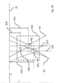
- Fig. 2B shows two adjacent focalized beams b1 and b2 with different focal depths FD1 and FD2 according to the present disclosure, for instance according to the example of Fig. 2A .
- focalized beam b1 has the focal depth FD1
- focalized beam b2 has the focal depth FD2. Due to the different focal depths FD1 and FD2, there is no non-overlapping area G between the two adjacent focalized beams b1 and b2.
- choosing adjacent focalized beams having different focal depths can prevent from obtaining a non-overlapping area G, while at the same time, keeping the same distance between the scanning line and thus maintaining the same framerate.
- Reconstructing the synthetic transmit beam STB may be conducted for a focal point of the STB, wherein the focal point of the STB is located in an overlapping area the two adjacent focalized beams b1 and b2.
- the synthetic transmit beam STB may be reconstructed based on signal data of the medium associated with both adjacent focalized beams b1 and b2 transmitted into the medium. Accordingly, since information (i.e. received signal data) related to the first beam b1 and information related to the second beam b2 are used to reconstruct the STB, the spatial region may advantageously be reconstructed more precisely at the focal point of the STB.
- Fig. 3B shows the focal depths FD1 and FD2 beyond an extension of the region of interest in the depth direction according to examples of the present disclosure.
- the focal depths FD1 is below the region of interest ROI in depth direction and FD2 is above the region of interest ROI in depth direction.
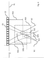
- FIG. 4 shows the adjacent focalized beams b1 and b2 that are offset OFS to each other and the adjacent focalized beams b1 and b2 are transmitted by a plurality of transducer elements 22 into the medium, according to examples of the present disclosure.
- a transducer array 23 may comprise the plurality of transducer elements 22 and the transducer elements 22 may be arranged along scanning lines SL1, SL2.
- focalized beams b1, b2, b3, b4, b5, b6, b7, and b8 are transmitted into the medium having two (or more; not shown in fig. 5 ) different focal depths according to examples of the present disclosure.
- the focalized beams b1, b3, b5, and b7 may have the same focal depth.
- the focalized beams b2, b4, b6, and b8 may have the same focal depth.
- One advantage of this embodiment is that a big amount of data about the medium may be obtained. Another advantage is that there may be no data missing out to non-overlapping areas or gaps.
- the system may further include a processing unit (not shown) for controlling the electronic control device 30 and/or for example for sending data to an external device, such as for example, a server, a computer on which an artificial intelligence (AI) algorithm is running, a dedicated workstation, presenting data, a device for displaying images obtained from the electronic control device or any of the other external devices.
- an external device such as for example, a server, a computer on which an artificial intelligence (AI) algorithm is running, a dedicated workstation, presenting data, a device for displaying images obtained from the electronic control device or any of the other external devices.
- the method according to the present disclosure in particular a beamforming method, may be carried out by at least one of the electronic control devices 30, the processing unit or any of the external devices.
- the process for compiling the ultrasound image data may be carried out by the same processing device as that one for optimizing the optimizing a process, or (at least in part) by another one.
- the system 100 may include at least one processing unit (or processor) and memory.
- the processor and memory unit may be incorporated into the system such as depicted in FIG. 6A or may be a computer or computer communicatively linked thereto.
- memory storing, instructions to evaluate ultrasound data or otherwise perform the methods described herein
- RAM volatile
- non-volatile such as RAM, flash memory, etc.
- the system 100 may also include storage devices (removable and/or non-removable) including, but not limited to, magnetic or optical disks or tape.
- the system 100 may also have input device(s) such as keyboard, mouse, pen, voice input, etc.
- connections such as LAN, WAN, point to point, etc.
- the connections may be operable to facility point-to-point communications, connection-oriented communications, connectionless communications, etc.
- the transducer elements 22 may comprise piezo-crystals and/or other components that may be configured to generate and/or record and/or receive signals.
- the terms transducer and transducer elements may be used synonymously throughout this disclosure unless denoted differently.
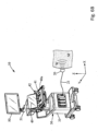
- Fig. 6B shows a schematic drawing of an ultrasound imaging system 10 according to examples of the present disclosure.
- the ultrasound imaging system 10 may be an example of a medical imaging system 200, as described in context of Fig. 6A .
- the display screen 50 may be a screen for visualizing the image processed by the processing unit 30.
- the display 50 may also visualize other information such as scales used in the image, or configuration information for the processing or any information such as help information or contextual gesture help for the touch pad 42.
- the display screen may by articulated on a support arm 51 for better positioning for the user.
- the display screen is usually a high definition screen of a great size (at least 20 inches) for better image visualization to the user.
- the control panel 40a is for example a portion of the system casing 31, said portion comprising a panel casing having a substantially flat surface inclined towards the user for manipulation by one hand of said user.
- the control panel 40a may be moved by a hanger upwards and downward for being adapted to the user size, and may be optionally moved frontward and rearward for being adapted to the user position.
- the control panel 40a may include a control panel display screen 49 for visualizing several configuration information or any information dedicated to the user .
- This control panel display screen 49 can also be hinged to the control panel casing 48 for being inclined into a different inclination than the control panel surface.
Landscapes
- Engineering & Computer Science (AREA)
- Physics & Mathematics (AREA)
- Radar, Positioning & Navigation (AREA)
- Remote Sensing (AREA)
- Computer Networks & Wireless Communication (AREA)
- General Physics & Mathematics (AREA)
- Acoustics & Sound (AREA)
- Life Sciences & Earth Sciences (AREA)
- Health & Medical Sciences (AREA)
- Pathology (AREA)
- Medical Informatics (AREA)
- Nuclear Medicine, Radiotherapy & Molecular Imaging (AREA)
- Veterinary Medicine (AREA)
- Radiology & Medical Imaging (AREA)
- Biomedical Technology (AREA)
- Heart & Thoracic Surgery (AREA)
- Biophysics (AREA)
- Molecular Biology (AREA)
- Surgery (AREA)
- Animal Behavior & Ethology (AREA)
- General Health & Medical Sciences (AREA)
- Public Health (AREA)
- Signal Processing (AREA)
- Multimedia (AREA)
- Ultra Sonic Daignosis Equipment (AREA)
Priority Applications (5)
| Application Number | Priority Date | Filing Date | Title |
|---|---|---|---|
| EP22315360.2A EP4394441A1 (de) | 2022-12-29 | 2022-12-29 | Strahlformungsverfahren und -system |
| JP2023191505A JP2024095978A (ja) | 2022-12-29 | 2023-11-09 | ビームフォーミング方法及びシステム |
| KR1020230159156A KR20240106958A (ko) | 2022-12-29 | 2023-11-16 | 빔포밍 방법 및 시스템 |
| CN202311699057.0A CN118282454A (zh) | 2022-12-29 | 2023-12-12 | 波束成形方法和系统 |
| US18/541,633 US20240219543A1 (en) | 2022-12-29 | 2023-12-15 | Beamforming method and system |
Applications Claiming Priority (1)
| Application Number | Priority Date | Filing Date | Title |
|---|---|---|---|
| EP22315360.2A EP4394441A1 (de) | 2022-12-29 | 2022-12-29 | Strahlformungsverfahren und -system |
Publications (1)
| Publication Number | Publication Date |
|---|---|
| EP4394441A1 true EP4394441A1 (de) | 2024-07-03 |
Family
ID=85283480
Family Applications (1)
| Application Number | Title | Priority Date | Filing Date |
|---|---|---|---|
| EP22315360.2A Pending EP4394441A1 (de) | 2022-12-29 | 2022-12-29 | Strahlformungsverfahren und -system |
Country Status (5)
| Country | Link |
|---|---|
| US (1) | US20240219543A1 (de) |
| EP (1) | EP4394441A1 (de) |
| JP (1) | JP2024095978A (de) |
| KR (1) | KR20240106958A (de) |
| CN (1) | CN118282454A (de) |
Citations (3)
| Publication number | Priority date | Publication date | Assignee | Title |
|---|---|---|---|---|
| WO2017093778A1 (en) | 2015-12-01 | 2017-06-08 | Super Sonic Imagine | An imaging method, an apparatus implementing said method, a computer program and a computer-readable storage medium |
| EP3207878A1 (de) * | 2014-10-15 | 2017-08-23 | Hitachi, Ltd. | Ultraschalldiagnosevorrichtung |
| US20220287685A1 (en) | 2021-03-09 | 2022-09-15 | GE Precision Healthcare LLC | Method and system for estimating motion from overlapping multiline acquisitions of successive ultrasound transmit events |
Family Cites Families (1)
| Publication number | Priority date | Publication date | Assignee | Title |
|---|---|---|---|---|
| US20140350406A1 (en) * | 2013-05-24 | 2014-11-27 | Siemens Medical Solutions Usa, Inc. | Dynamic Operation for Subarrays in Medical Diagnostic Ultrasound Imaging |
-
2022
- 2022-12-29 EP EP22315360.2A patent/EP4394441A1/de active Pending
-
2023
- 2023-11-09 JP JP2023191505A patent/JP2024095978A/ja active Pending
- 2023-11-16 KR KR1020230159156A patent/KR20240106958A/ko not_active Ceased
- 2023-12-12 CN CN202311699057.0A patent/CN118282454A/zh active Pending
- 2023-12-15 US US18/541,633 patent/US20240219543A1/en active Pending
Patent Citations (3)
| Publication number | Priority date | Publication date | Assignee | Title |
|---|---|---|---|---|
| EP3207878A1 (de) * | 2014-10-15 | 2017-08-23 | Hitachi, Ltd. | Ultraschalldiagnosevorrichtung |
| WO2017093778A1 (en) | 2015-12-01 | 2017-06-08 | Super Sonic Imagine | An imaging method, an apparatus implementing said method, a computer program and a computer-readable storage medium |
| US20220287685A1 (en) | 2021-03-09 | 2022-09-15 | GE Precision Healthcare LLC | Method and system for estimating motion from overlapping multiline acquisitions of successive ultrasound transmit events |
Non-Patent Citations (2)
| Title |
|---|
| MOO-HO BAEMOK-KUN JEONG: "A study of synthetic-aperture imaging with virtual source elements in B-mode ultrasound imaging systems", IEEE TRANSACTIONS ON ULTRASONICS, FERROELECTRICS, AND FREQUENCY CONTROL, vol. 47, no. 6, November 2000 (2000-11-01), pages 1510 - 1519, XP011438231, DOI: 10.1109/58.883540 |
| T. HERGUMT. BJASTADK. KRISTOFFERSENH. TORP: "Parallel beamforming using synthetic transmit beams", IEEE TRANSACTIONS ON ULTRASONICS, FERROELECTRICS, AND FREQUENCY CONTROL, vol. 54, no. 2, February 2007 (2007-02-01), pages 271 - 280 |
Also Published As
| Publication number | Publication date |
|---|---|
| CN118282454A9 (zh) | 2024-08-09 |
| CN118282454A (zh) | 2024-07-02 |
| KR20240106958A (ko) | 2024-07-08 |
| JP2024095978A (ja) | 2024-07-11 |
| US20240219543A1 (en) | 2024-07-04 |
Similar Documents
| Publication | Publication Date | Title |
|---|---|---|
| Jensen et al. | Anatomic and functional imaging using row–column arrays | |
| EP3154436B1 (de) | Vorrichtung und verfahren zur hybriden optoakustischen tomografie und ultraschallsonografie | |
| US11846608B2 (en) | Image reconstruction method based on a trained non-linear mapping | |
| Montaldo et al. | Coherent plane-wave compounding for very high frame rate ultrasonography and transient elastography | |
| JP6408297B2 (ja) | ビームフォーミング方法、計測イメージング装置、及び、通信装置 | |
| KR101942595B1 (ko) | 영상 획득속도 최적화를 구비한 영상장치 | |
| CN114119362A (zh) | 利用神经网络提高超声图像分辨率的系统和方法 | |
| CN109363714B (zh) | 一种超声成像设备及其超声成像方法 | |
| JP2019535448A (ja) | 超音波画像クラッタをフィルタリングする方法及びシステム | |
| JP2007513672A (ja) | 2次元アレイトランスデューサを用いる立体的超音波画像化システム | |
| CN106137125A (zh) | 被检体信息获取设备 | |
| KR20230088284A (ko) | 빔형성된 데이터를 처리하는 방법 및 시스템 | |
| JP2018535789A (ja) | イメージング方法、前記方法を実施する装置、コンピュータプログラム、およびコンピュータ可読記憶媒体 | |
| US11272906B2 (en) | Ultrasonic imaging device and method for controlling same | |
| Cohen et al. | Sparse convolutional beamforming for 3-D ultrafast ultrasound imaging | |
| JP7167045B2 (ja) | 音響センサーを位置決めするためのロケーションデバイス及びシステム | |
| JP2023114623A (ja) | 超音波診断装置 | |
| US20240000430A1 (en) | Processing ultrasound scan data | |
| US8235906B2 (en) | System and method for accelerated focused ultrasound imaging | |
| KR20140137037A (ko) | 초음파 영상 처리 장치 및 방법 | |
| JP2017140092A (ja) | 被検体情報取得装置 | |
| CN114846510A (zh) | 根据多个不同地扰动的基于模型的解剖图像分割的节点变化来生成分割置信度图 | |
| JP2005342140A (ja) | 超音波送受信装置及び超音波送受信方法 | |
| EP4394441A1 (de) | Strahlformungsverfahren und -system | |
| Andresen et al. | Synthetic aperture focusing for a single-element transducer undergoing helical motion |
Legal Events
| Date | Code | Title | Description |
|---|---|---|---|
| PUAI | Public reference made under article 153(3) epc to a published international application that has entered the european phase |
Free format text: ORIGINAL CODE: 0009012 |
|
| STAA | Information on the status of an ep patent application or granted ep patent |
Free format text: STATUS: THE APPLICATION HAS BEEN PUBLISHED |
|
| AK | Designated contracting states |
Kind code of ref document: A1 Designated state(s): AL AT BE BG CH CY CZ DE DK EE ES FI FR GB GR HR HU IE IS IT LI LT LU LV MC ME MK MT NL NO PL PT RO RS SE SI SK SM TR |
|
| STAA | Information on the status of an ep patent application or granted ep patent |
Free format text: STATUS: REQUEST FOR EXAMINATION WAS MADE |
|
| 17P | Request for examination filed |
Effective date: 20241217 |
|
| RAP3 | Party data changed (applicant data changed or rights of an application transferred) |
Owner name: SUPERSONIC IMAGINE |