EP4394540A1 - Endgerät und kommunikationsverfahren - Google Patents
Endgerät und kommunikationsverfahren Download PDFInfo
- Publication number
- EP4394540A1 EP4394540A1 EP21954992.0A EP21954992A EP4394540A1 EP 4394540 A1 EP4394540 A1 EP 4394540A1 EP 21954992 A EP21954992 A EP 21954992A EP 4394540 A1 EP4394540 A1 EP 4394540A1
- Authority
- EP
- European Patent Office
- Prior art keywords
- signal
- terminal
- power supplying
- base station
- information
- Prior art date
- Legal status (The legal status is an assumption and is not a legal conclusion. Google has not performed a legal analysis and makes no representation as to the accuracy of the status listed.)
- Pending
Links
Images




Classifications
-
- H—ELECTRICITY
- H02—GENERATION; CONVERSION OR DISTRIBUTION OF ELECTRIC POWER
- H02J—ELECTRIC POWER NETWORKS; CIRCUIT ARRANGEMENTS OR SYSTEMS FOR SUPPLYING OR DISTRIBUTING ELECTRIC POWER; SYSTEMS FOR STORING ELECTRIC ENERGY
- H02J50/00—Circuit arrangements or systems for wireless supply or distribution of electric power
- H02J50/001—Energy harvesting or scavenging
-
- H—ELECTRICITY
- H02—GENERATION; CONVERSION OR DISTRIBUTION OF ELECTRIC POWER
- H02J—ELECTRIC POWER NETWORKS; CIRCUIT ARRANGEMENTS OR SYSTEMS FOR SUPPLYING OR DISTRIBUTING ELECTRIC POWER; SYSTEMS FOR STORING ELECTRIC ENERGY
- H02J50/00—Circuit arrangements or systems for wireless supply or distribution of electric power
- H02J50/20—Circuit arrangements or systems for wireless supply or distribution of electric power using microwaves or radio frequency waves
-
- H—ELECTRICITY
- H02—GENERATION; CONVERSION OR DISTRIBUTION OF ELECTRIC POWER
- H02J—ELECTRIC POWER NETWORKS; CIRCUIT ARRANGEMENTS OR SYSTEMS FOR SUPPLYING OR DISTRIBUTING ELECTRIC POWER; SYSTEMS FOR STORING ELECTRIC ENERGY
- H02J50/00—Circuit arrangements or systems for wireless supply or distribution of electric power
- H02J50/80—Circuit arrangements or systems for wireless supply or distribution of electric power involving the exchange of data, concerning supply or distribution of electric power, between transmitting devices and receiving devices
-
- H—ELECTRICITY
- H04—ELECTRIC COMMUNICATION TECHNIQUE
- H04B—TRANSMISSION
- H04B5/00—Near-field transmission systems, e.g. inductive or capacitive transmission systems
- H04B5/70—Near-field transmission systems, e.g. inductive or capacitive transmission systems specially adapted for specific purposes
- H04B5/79—Near-field transmission systems, e.g. inductive or capacitive transmission systems specially adapted for specific purposes for data transfer in combination with power transfer
-
- Y—GENERAL TAGGING OF NEW TECHNOLOGICAL DEVELOPMENTS; GENERAL TAGGING OF CROSS-SECTIONAL TECHNOLOGIES SPANNING OVER SEVERAL SECTIONS OF THE IPC; TECHNICAL SUBJECTS COVERED BY FORMER USPC CROSS-REFERENCE ART COLLECTIONS [XRACs] AND DIGESTS
- Y02—TECHNOLOGIES OR APPLICATIONS FOR MITIGATION OR ADAPTATION AGAINST CLIMATE CHANGE
- Y02D—CLIMATE CHANGE MITIGATION TECHNOLOGIES IN INFORMATION AND COMMUNICATION TECHNOLOGIES [ICT], I.E. INFORMATION AND COMMUNICATION TECHNOLOGIES AIMING AT THE REDUCTION OF THEIR OWN ENERGY USE
- Y02D30/00—Reducing energy consumption in communication networks
- Y02D30/70—Reducing energy consumption in communication networks in wireless communication networks
Definitions
- NR New Radio
- a terminal includes: a reception unit configured to receive a power supplying signal from another device and to receive power supply; and a control unit configured to control an operation of receiving the power supplying signal.
- the power supplying signal includes a signal used for energy harvesting and a signal used for a purpose other than the energy harvesting, and the another device includes a base station and another terminal.
- SS Synchronization signal
- PSS Primary SS
- SSS Synchronization SS
- PBCH Physical broadcast channel
- PRACH Physical random access channel
- PDCCH Physical Downlink Control Channel
- PDSCH Physical Downlink Shared Channel
- PUCCH Physical Uplink Control Channel
- PUSCH Physical Uplink Shared Channel
- the duplex method may be a TDD (Time Division Duplex) method, an FDD (Frequency Division Duplex) method, or any other method (e.g., Flexible Duplex, or the like).
- TDD Time Division Duplex
- FDD Frequency Division Duplex
- any other method e.g., Flexible Duplex, or the like.
- radio (wireless) parameters are "configured (set)" may mean that a predetermined value is pre-configured, or may mean that a radio parameter indicated by the base station 10 or the terminal 20 is configured.
- Fig. 1 is a drawing illustrating a wireless communication system according to an embodiment of the present invention.
- a wireless communication system according to an embodiment of the present invention includes a base station 10 and a terminal 20.
- a single base station 10 and a single terminal 20 are illustrated as an example.
- a signal or channel used for supplying power to the terminal 20 may be 1) to 3) described below.
- information related to a UL signal of another terminal 20 may be transmitted from the base station 10 or from another terminal 20 as the information related to a power supplying signal.
- the terminal 20 may receive a UL signal or SL signal that can be used as a power supplying signal from a terminal 20 with extra amount of power such as a terminal 20 to which power is sufficiently supplied.
- a condition for a terminal 20 to transmit a power supplying signal may be indicated by the network or may be defined in the technical specifications.
- the condition may be a threshold value related to power.
- information indicating whether a power supplying signal is to be transmitted may be indicated from the network to the terminal 20.
- the indication may be transmitted via DCI, MAC-CE, or RRC signaling.
- the terminal 20 may configure or update the beam to be applied to the power supplying signal.
- the terminal 20 may indicate the selected beam or power supplying signal to the network.
- a condition for selecting a beam, a threshold value, or the like may be indicated by the network or may be defined in the technical specifications.
- the beam may mean a transmission beam or may mean a reception beam in an embodiment of the present invention.
- the terminal 20 may apply a beam used for another channel or another signal to the power supplying signal or may associate the beam with the power supplying signal.
- the associated corresponding relationship between the beam for another channel or another signal and the power supplying signal may be indicated or defined.
- the network may indicate, to the terminal 20, the beam to be applied to the power supplying signal, or may indicate, to the terminal 20, a beam used by one or more terminals 20 among the beams applied to the power supplying signal.
- an operation related to a power supplying signal may be switched depending on a state or type of the terminal 20 such as a connected mode, an idle/inactive mode, a state related to mobility.
- the terminal 20 may use a conventional signal such as an SSB as the power supplying signal when the terminal 20 is in an idle/inactive mode, or may use a control signal, a data signal and/or an energy harvesting reference signal as the power supplying signal when the terminal 20 is in a connected mode.
- the coverage of the power supplying signal may be larger than the coverage of a normal signal, or may be smaller than the coverage of a normal signal.
- Information indicating the transmission power of the power supplying signal may be indicated by the network.
- the information may be indicated by using an absolute value, or may be indicated by using a relative value or the like with respect to another signal, etc.
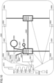
- a driving support system unit 2030 includes: various devices for providing functions of preventing accidents and reducing driver's operating loads such as a millimeter wave radar, a LiDAR (Light Detection and Ranging), a camera, a positioning locator (e.g., GNSS, etc.), map information (e.g., high definition (HD) map, autonomous vehicle (AV) map, etc.), a gyro system (e.g., IMU (Inertial Measurement Unit), INS (Inertial Navigation System), etc.), an AI (Artificial Intelligence) chip, an AI processor; and one or more ECUs controlling these devices.
- the driving support system unit 2030 transmits and receives various types of information via the communication module 2013 to realize a driving support function or an autonomous driving function.
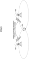
- a coverage according to the signal used for the energy harvesting may be different from a coverage of the signal used for a purpose other than the energy harvesting.
- the terminal 20 can perform energy harvesting by efficiently receiving the power supplying signal from the base station 10.
- the terminal 20 can perform energy harvesting by receiving the power supplying signal from the base station 10 or another terminal 20. That is, the power supply using a wireless signal can be achieved in a wireless communication system.
- the software executed by a processor included in the base station 10 according to an embodiment of the present invention and the software executed by a processor included in the terminal 20 according to an embodiment of the present invention may be stored in a random access memory (RAM), a flash memory, a read only memory (ROM), an EPROM, an EEPROM, a register, a hard disk (HDD), a removable disk, a CD-ROM, a database, a server, or any other appropriate recording medium.
- RAM random access memory
- ROM read only memory
- EPROM an EPROM
- EEPROM electrically erasable programmable read-only memory
- register a register
- HDD hard disk
- CD-ROM compact disc-read only memory
- database a database
- server or any other appropriate recording medium.
- Software should be broadly interpreted to mean, whether referred to as software, firmware, middle-ware, microcode, hardware description language, or any other name, instructions, instruction sets, codes, code segments, program codes, programs, subprograms, software modules, applications, software applications, software packages, routines, subroutines, objects, executable files, executable threads, procedures, functions, and the like.
- software, instructions, information, and the like may be transmitted and received via a transmission medium.
- a transmission medium such as coaxial cable, fiber optic cable, twisted pair, digital subscriber line (DSL) and wireless technologies (infrared, microwave, etc.)
- wired line technologies such as coaxial cable, fiber optic cable, twisted pair, digital subscriber line (DSL) and wireless technologies (infrared, microwave, etc.
- DSL digital subscriber line
- wireless technologies infrared, microwave, etc.
- Information, a signal, or the like, described in the present specification may represented by using any one of various different technologies.
- data, an instruction, a command, information, a signal, a bit, a symbol, a chip, or the like, described throughout the present application may be represented by a voltage, an electric current, electromagnetic waves, magnetic fields, a magnetic particle, optical fields, a photon, or a combination thereof.
- BS Base Station
- Radio Base Station Base Station
- Base Station Wireless Local Area Network
- NodeB NodeB
- eNodeB eNodeB
- gNodeB gNB
- Access Point "Transmission Point”
- Reception Point Transmission/Reception Point
- Cell Cell
- Sector Cell Group
- Carrier Carrier
- Component Carrier and the like
- the base station may be referred to as a macro-cell, a small cell, a femtocell, a picocell and the like.
- At least one of the base station and the mobile station may be referred to as a transmission apparatus, reception apparatus, communication apparatus, or the like.
- the at least one of the base station and the mobile station may be a device mounted on the mobile station, the mobile station itself, or the like.
- the mobile station may be a vehicle (e.g., a car, an airplane, etc.), an unmanned mobile body (e.g., a drone, an automated vehicle, etc.), or a robot (manned or unmanned).
- At least one of the base station and the mobile station may include an apparatus that does not necessarily move during communication operations.
- at least one of the base station and the mobile station may be an IoT (Internet of Things) device such as a sensor.
- IoT Internet of Things
- the term “determining” used in the present specification may include various actions or operations.
- the term “determining” may include, for example, a case in which "judging", “calculating”, “computing”, “processing”, “deriving”, “investigating”, “looking up, search, inquiry” (e.g., looking up a table, database, or other data structures), or “ascertaining” is deemed as “determining”.
- the “determining” may include a case in which “receiving” (e.g., receiving information), “transmitting” (e.g., transmitting information), “inputting", “outputting”, or “accessing” (e.g., accessing data in a memory) is deemed as “determining”.
- the "determining” may include a case in which “resolving”, “selecting”, “choosing”, “establishing”, “comparing”, or the like is deemed as “determining”.
- the “determining” may include a case in which a certain action or operation is deemed as “determining”.
- “decision” may be read as “assuming", “expecting”, or “considering”, etc.
- connection means any direct or indirect connection or connection between two or more elements and may include the presence of one or more intermediate elements between the two elements “connected” or “coupled” with each other.
- the coupling or connection between the elements may be physical, logical, or a combination thereof.
- connection may be read as "access”.
- the two elements may be thought of as being “connected” or “coupled” to each other using at least one of the one or more wires, cables, and printed electrical connections and, as a number of non-limiting and non-inclusive examples, electromagnetic energy having wavelengths in the radio frequency region, the microwave region, and the light (both visible and invisible) region.
- the numerology may be a communication parameter that is applied to at least one of the transmission or reception of a signal or channel.
- the numerology may indicate at least one of, for example, SubCarrier Spacing (SCS), bandwidth, symbol length, cyclic prefix length, transmission time interval (TTI), number of symbols per TTI, radio frame configuration, specific filtering processing performed by the transceiver in the frequency domain, and specific windowing processing performed by the transceiver in the time domain.
- SCS SubCarrier Spacing
- TTI transmission time interval
- radio frame configuration specific filtering processing performed by the transceiver in the frequency domain
- specific windowing processing performed by the transceiver in the time domain specific windowing processing performed by the transceiver in the time domain.
- a TTI having a time length of 1 ms may be referred to as a normal TTI (a TTI in LTE Rel. 8-12), a long TTI, a normal subframe, a long subframe, a slot, and the like.
- a TTI that is shorter than the normal TTI may be referred to as a shortened TTI, a short TTI, a partial TTI (or fractional TTI), a shortened subframe, a short subframe, a mini slot, a subslot, a slot, or the like.
- the long TTI e.g., normal TTI, subframe, etc.
- the short TTI e.g., shortened TTI, etc.
- the long TTI may be replaced with a TTI having a time length exceeding 1 ms
- the short TTI e.g., shortened TTI, etc.,
- the long TTI may be replaced with a TTI having a TTI length less than the TTI length of the long TTI and a TTI length greater than 1 ms.
- a resource block is a time domain and frequency domain resource allocation unit and may include one or more consecutive subcarriers in the frequency domain.
- the number of subcarriers included in an RB may be the same, regardless of the numerology, and may be 12, for example.
- the number of subcarriers included in an RB may be determined on the basis of numerology.
- the time domain of an RB may include one or more symbols, which may be 1 slot, 1 mini slot, 1 subframe, or 1 TTI in length.
- One TTI, one subframe, etc. may each include one or more resource blocks.
- one or more RBs may be referred to as physical resource blocks (PRBs, Physical RBs), sub-carrier groups (SCGs), resource element groups (REGs), PRB pairs, RB pairs, and the like.
- PRBs physical resource blocks
- SCGs sub-carrier groups
- REGs resource element groups
- PRB pairs RB pairs, and the like.
- a resource block may include one or more resource elements (RE).
- RE resource elements
- 1 RE may be a radio resource area of one sub-carrier and one symbol.
- the bandwidth part (which may also be referred to as a partial bandwidth, etc.) may represent a subset of consecutive common RBs (common resource blocks) for a given numerology in a carrier.
- a common RB may be identified by an index of RB relative to the common reference point of the carrier.
- a PRB may be defined in a BWP and may be numbered within the BWP.
- BWP may include BWP for UL (UL BWP) and BWP for DL (DL BWP).
- BWP for a terminal 20
- one or more BWPs may be configured in one carrier.
- At least one of the configured BWPs may be activated, and the terminal 20 may assume that the terminal 20 will not transmit and receive signals/channels outside the activated BWP. It should be noted that the terms "cell” and “carrier” in this disclosure may be replaced by "BWP.”
- the term "A and B are different” may mean “A and B are different from each other.” It should be noted that the term “A and B are different” may mean “A and B are different from C.” Terms such as “separated” or “combined” may be interpreted in the same way as the above-described "different”.
- notification (transmission/reporting) of predetermined information is not limited to an explicit notification (transmission/reporting), and may be performed by an implicit notification (transmission/reporting) (e.g., by not performing notification (transmission/reporting) of the predetermined information).
Landscapes
- Engineering & Computer Science (AREA)
- Computer Networks & Wireless Communication (AREA)
- Power Engineering (AREA)
- Signal Processing (AREA)
- Mobile Radio Communication Systems (AREA)
Applications Claiming Priority (1)
| Application Number | Priority Date | Filing Date | Title |
|---|---|---|---|
| PCT/JP2021/031060 WO2023026378A1 (ja) | 2021-08-24 | 2021-08-24 | 端末及び通信方法 |
Publications (2)
| Publication Number | Publication Date |
|---|---|
| EP4394540A1 true EP4394540A1 (de) | 2024-07-03 |
| EP4394540A4 EP4394540A4 (de) | 2025-09-24 |
Family
ID=85321895
Family Applications (1)
| Application Number | Title | Priority Date | Filing Date |
|---|---|---|---|
| EP21954992.0A Pending EP4394540A4 (de) | 2021-08-24 | 2021-08-24 | Endgerät und kommunikationsverfahren |
Country Status (5)
| Country | Link |
|---|---|
| US (1) | US20250141262A1 (de) |
| EP (1) | EP4394540A4 (de) |
| JP (1) | JP7684407B2 (de) |
| CN (1) | CN117813742A (de) |
| WO (1) | WO2023026378A1 (de) |
Families Citing this family (12)
| Publication number | Priority date | Publication date | Assignee | Title |
|---|---|---|---|---|
| WO2024195137A1 (ja) * | 2023-03-23 | 2024-09-26 | 株式会社Nttドコモ | 端末及び給電方法 |
| WO2024195136A1 (ja) * | 2023-03-23 | 2024-09-26 | 株式会社Nttドコモ | 端末及び給電方法 |
| JPWO2024201759A1 (de) * | 2023-03-28 | 2024-10-03 | ||
| WO2024218887A1 (ja) * | 2023-04-19 | 2024-10-24 | 株式会社Nttドコモ | 端末、基地局及び通信方法 |
| JP2025005207A (ja) * | 2023-06-27 | 2025-01-16 | 京セラ株式会社 | 送電装置、制御方法及び制御プログラム |
| CN121128274A (zh) * | 2023-07-06 | 2025-12-12 | 株式会社Ntt都科摩 | 终端以及供电方法 |
| WO2025009181A1 (ja) * | 2023-07-06 | 2025-01-09 | 株式会社Nttドコモ | 端末及び給電方法 |
| CN121420486A (zh) * | 2023-07-13 | 2026-01-27 | 松下电器(美国)知识产权公司 | 无线装置及控制方法 |
| CN119382811A (zh) * | 2023-07-27 | 2025-01-28 | 中兴通讯股份有限公司 | 通信方法、装置及存储介质 |
| WO2025109691A1 (ja) * | 2023-11-21 | 2025-05-30 | 富士通株式会社 | 端末装置、基地局装置及び無線通信システム |
| WO2025234180A1 (ja) * | 2024-05-08 | 2025-11-13 | パナソニック インテレクチュアル プロパティ コーポレーション オブ アメリカ | 無線通信装置、無線装置及び無線方法 |
| WO2026004014A1 (ja) * | 2024-06-26 | 2026-01-02 | 1Finity株式会社 | 通信装置、基地局、及び通信システム |
Family Cites Families (6)
| Publication number | Priority date | Publication date | Assignee | Title |
|---|---|---|---|---|
| CA2614482A1 (en) * | 2005-07-08 | 2007-01-18 | Powercast Corporation | Power transmission system, apparatus and method with communication |
| US9332134B2 (en) * | 2011-08-25 | 2016-05-03 | Telefonaktiebolaget L M Ericsson | Charging of battery-operated devices over wireless connections |
| JP6145741B1 (ja) * | 2016-12-27 | 2017-06-14 | パナソニックIpマネジメント株式会社 | エナジーハーベスト端末 |
| JP6403036B1 (ja) * | 2018-03-30 | 2018-10-10 | パナソニックIpマネジメント株式会社 | エナジーハーベスト端末 |
| CN119482994A (zh) * | 2018-08-02 | 2025-02-18 | 麦克赛尔株式会社 | 无线终端装置以及无线供电装置 |
| US12040630B2 (en) * | 2021-05-26 | 2024-07-16 | Qualcomm Incorporated | Signaling for energy harvesting at a device |
-
2021
- 2021-08-24 CN CN202180101558.7A patent/CN117813742A/zh active Pending
- 2021-08-24 EP EP21954992.0A patent/EP4394540A4/de active Pending
- 2021-08-24 US US18/683,108 patent/US20250141262A1/en active Pending
- 2021-08-24 JP JP2023543536A patent/JP7684407B2/ja active Active
- 2021-08-24 WO PCT/JP2021/031060 patent/WO2023026378A1/ja not_active Ceased
Also Published As
| Publication number | Publication date |
|---|---|
| US20250141262A1 (en) | 2025-05-01 |
| JPWO2023026378A1 (de) | 2023-03-02 |
| CN117813742A (zh) | 2024-04-02 |
| WO2023026378A1 (ja) | 2023-03-02 |
| JP7684407B2 (ja) | 2025-05-27 |
| EP4394540A4 (de) | 2025-09-24 |
Similar Documents
| Publication | Publication Date | Title |
|---|---|---|
| EP4394540A1 (de) | Endgerät und kommunikationsverfahren | |
| US20250184992A1 (en) | Terminal, base station and communication method | |
| EP4507432A1 (de) | Endgerät, basisstation und kommunikationsverfahren | |
| EP4496406A1 (de) | Endgerät, basisstation und kommunikationsverfahren | |
| EP4462918A1 (de) | Endgerät, basisstation und kommunikationsverfahren | |
| US20240334418A1 (en) | Terminal and communication method | |
| US20250097953A1 (en) | Terminal and communication method | |
| US20240397489A1 (en) | Terminal, base station and communication method | |
| US20240397498A1 (en) | Terminal and communication method | |
| US20240397510A1 (en) | Terminal and communication method | |
| EP4408066A1 (de) | Endgerät und kommunikationsverfahren | |
| US20250183960A1 (en) | Terminal, base station and communication method | |
| US20250089079A1 (en) | Terminal, base station and communication method | |
| US20250227643A1 (en) | Terminal, base station and communication method | |
| US20250105964A1 (en) | Terminal, base station and communication method | |
| EP4422257A1 (de) | Endgerät und kommunikationsverfahren | |
| EP4486030A1 (de) | Endgerät, basisstation, drahtloses kommunikationssystem und kommunikationsverfahren | |
| US20240381326A1 (en) | Terminal and communication method | |
| EP4492896A1 (de) | Endgerät, basisstation und kommunikationsverfahren | |
| US20250192960A1 (en) | Terminal, base station and communication method | |
| EP4395421A1 (de) | Endgerät und kommunikationsverfahren | |
| EP4391680A1 (de) | Endgerät und kommunikationsverfahren | |
| US20250212070A1 (en) | Terminal, base station and communication method | |
| US20250113379A1 (en) | Terminal and communication method | |
| EP4478810A1 (de) | Endgerät und kommunikationsverfahren |
Legal Events
| Date | Code | Title | Description |
|---|---|---|---|
| STAA | Information on the status of an ep patent application or granted ep patent |
Free format text: STATUS: THE INTERNATIONAL PUBLICATION HAS BEEN MADE |
|
| PUAI | Public reference made under article 153(3) epc to a published international application that has entered the european phase |
Free format text: ORIGINAL CODE: 0009012 |
|
| STAA | Information on the status of an ep patent application or granted ep patent |
Free format text: STATUS: REQUEST FOR EXAMINATION WAS MADE |
|
| 17P | Request for examination filed |
Effective date: 20240313 |
|
| AK | Designated contracting states |
Kind code of ref document: A1 Designated state(s): AL AT BE BG CH CY CZ DE DK EE ES FI FR GB GR HR HU IE IS IT LI LT LU LV MC MK MT NL NO PL PT RO RS SE SI SK SM TR |
|
| DAV | Request for validation of the european patent (deleted) | ||
| DAX | Request for extension of the european patent (deleted) | ||
| A4 | Supplementary search report drawn up and despatched |
Effective date: 20250825 |
|
| RIC1 | Information provided on ipc code assigned before grant |
Ipc: G05F 1/67 20060101AFI20250819BHEP Ipc: H02J 50/20 20160101ALI20250819BHEP Ipc: H02J 50/80 20160101ALI20250819BHEP Ipc: H04B 5/79 20240101ALI20250819BHEP |