EP4394570A1 - Verfahren zur erweiterung der anzeige einer elektronischen vorrichtung und elektronische vorrichtung zur unterstützung davon - Google Patents
Verfahren zur erweiterung der anzeige einer elektronischen vorrichtung und elektronische vorrichtung zur unterstützung davon Download PDFInfo
- Publication number
- EP4394570A1 EP4394570A1 EP22881347.3A EP22881347A EP4394570A1 EP 4394570 A1 EP4394570 A1 EP 4394570A1 EP 22881347 A EP22881347 A EP 22881347A EP 4394570 A1 EP4394570 A1 EP 4394570A1
- Authority
- EP
- European Patent Office
- Prior art keywords
- electronic device
- area
- display
- state
- screen
- Prior art date
- Legal status (The legal status is an assumption and is not a legal conclusion. Google has not performed a legal analysis and makes no representation as to the accuracy of the status listed.)
- Granted
Links
Images







Classifications
-
- G—PHYSICS
- G06—COMPUTING OR CALCULATING; COUNTING
- G06F—ELECTRIC DIGITAL DATA PROCESSING
- G06F3/00—Input arrangements for transferring data to be processed into a form capable of being handled by the computer; Output arrangements for transferring data from processing unit to output unit, e.g. interface arrangements
- G06F3/01—Input arrangements or combined input and output arrangements for interaction between user and computer
- G06F3/048—Interaction techniques based on graphical user interfaces [GUI]
- G06F3/0484—Interaction techniques based on graphical user interfaces [GUI] for the control of specific functions or operations, e.g. selecting or manipulating an object, an image or a displayed text element, setting a parameter value or selecting a range
-
- G—PHYSICS
- G09—EDUCATION; CRYPTOGRAPHY; DISPLAY; ADVERTISING; SEALS
- G09G—ARRANGEMENTS OR CIRCUITS FOR CONTROL OF INDICATING DEVICES USING STATIC MEANS TO PRESENT VARIABLE INFORMATION
- G09G3/00—Control arrangements or circuits, of interest only in connection with visual indicators other than cathode-ray tubes
- G09G3/03—Control arrangements or circuits, of interest only in connection with visual indicators other than cathode-ray tubes specially adapted for displays having non-planar surfaces, e.g. curved displays
- G09G3/035—Control arrangements or circuits, of interest only in connection with visual indicators other than cathode-ray tubes specially adapted for displays having non-planar surfaces, e.g. curved displays for flexible display surfaces
-
- G—PHYSICS
- G06—COMPUTING OR CALCULATING; COUNTING
- G06F—ELECTRIC DIGITAL DATA PROCESSING
- G06F1/00—Details not covered by groups G06F3/00 - G06F13/00 and G06F21/00
- G06F1/16—Constructional details or arrangements
- G06F1/1613—Constructional details or arrangements for portable computers
- G06F1/1615—Constructional details or arrangements for portable computers with several enclosures having relative motions, each enclosure supporting at least one I/O or computing function
- G06F1/1624—Constructional details or arrangements for portable computers with several enclosures having relative motions, each enclosure supporting at least one I/O or computing function with sliding enclosures, e.g. sliding keyboard or display
-
- G—PHYSICS
- G06—COMPUTING OR CALCULATING; COUNTING
- G06F—ELECTRIC DIGITAL DATA PROCESSING
- G06F1/00—Details not covered by groups G06F3/00 - G06F13/00 and G06F21/00
- G06F1/16—Constructional details or arrangements
- G06F1/1613—Constructional details or arrangements for portable computers
- G06F1/1633—Constructional details or arrangements of portable computers not specific to the type of enclosures covered by groups G06F1/1615 - G06F1/1626
- G06F1/1637—Details related to the display arrangement, including those related to the mounting of the display in the housing
- G06F1/1643—Details related to the display arrangement, including those related to the mounting of the display in the housing the display being associated to a digitizer, e.g. laptops that can be used as penpads
-
- G—PHYSICS
- G06—COMPUTING OR CALCULATING; COUNTING
- G06F—ELECTRIC DIGITAL DATA PROCESSING
- G06F3/00—Input arrangements for transferring data to be processed into a form capable of being handled by the computer; Output arrangements for transferring data from processing unit to output unit, e.g. interface arrangements
- G06F3/01—Input arrangements or combined input and output arrangements for interaction between user and computer
- G06F3/048—Interaction techniques based on graphical user interfaces [GUI]
- G06F3/0481—Interaction techniques based on graphical user interfaces [GUI] based on specific properties of the displayed interaction object or a metaphor-based environment, e.g. interaction with desktop elements like windows or icons, or assisted by a cursor's changing behaviour or appearance
-
- G—PHYSICS
- G06—COMPUTING OR CALCULATING; COUNTING
- G06F—ELECTRIC DIGITAL DATA PROCESSING
- G06F3/00—Input arrangements for transferring data to be processed into a form capable of being handled by the computer; Output arrangements for transferring data from processing unit to output unit, e.g. interface arrangements
- G06F3/01—Input arrangements or combined input and output arrangements for interaction between user and computer
- G06F3/048—Interaction techniques based on graphical user interfaces [GUI]
- G06F3/0487—Interaction techniques based on graphical user interfaces [GUI] using specific features provided by the input device, e.g. functions controlled by the rotation of a mouse with dual sensing arrangements, or of the nature of the input device, e.g. tap gestures based on pressure sensed by a digitiser
- G06F3/0488—Interaction techniques based on graphical user interfaces [GUI] using specific features provided by the input device, e.g. functions controlled by the rotation of a mouse with dual sensing arrangements, or of the nature of the input device, e.g. tap gestures based on pressure sensed by a digitiser using a touch-screen or digitiser, e.g. input of commands through traced gestures
-
- G—PHYSICS
- G06—COMPUTING OR CALCULATING; COUNTING
- G06F—ELECTRIC DIGITAL DATA PROCESSING
- G06F3/00—Input arrangements for transferring data to be processed into a form capable of being handled by the computer; Output arrangements for transferring data from processing unit to output unit, e.g. interface arrangements
- G06F3/01—Input arrangements or combined input and output arrangements for interaction between user and computer
- G06F3/048—Interaction techniques based on graphical user interfaces [GUI]
- G06F3/0487—Interaction techniques based on graphical user interfaces [GUI] using specific features provided by the input device, e.g. functions controlled by the rotation of a mouse with dual sensing arrangements, or of the nature of the input device, e.g. tap gestures based on pressure sensed by a digitiser
- G06F3/0488—Interaction techniques based on graphical user interfaces [GUI] using specific features provided by the input device, e.g. functions controlled by the rotation of a mouse with dual sensing arrangements, or of the nature of the input device, e.g. tap gestures based on pressure sensed by a digitiser using a touch-screen or digitiser, e.g. input of commands through traced gestures
- G06F3/04883—Interaction techniques based on graphical user interfaces [GUI] using specific features provided by the input device, e.g. functions controlled by the rotation of a mouse with dual sensing arrangements, or of the nature of the input device, e.g. tap gestures based on pressure sensed by a digitiser using a touch-screen or digitiser, e.g. input of commands through traced gestures for inputting data by handwriting, e.g. gesture or text
-
- G—PHYSICS
- G06—COMPUTING OR CALCULATING; COUNTING
- G06F—ELECTRIC DIGITAL DATA PROCESSING
- G06F3/00—Input arrangements for transferring data to be processed into a form capable of being handled by the computer; Output arrangements for transferring data from processing unit to output unit, e.g. interface arrangements
- G06F3/01—Input arrangements or combined input and output arrangements for interaction between user and computer
- G06F3/048—Interaction techniques based on graphical user interfaces [GUI]
- G06F3/0487—Interaction techniques based on graphical user interfaces [GUI] using specific features provided by the input device, e.g. functions controlled by the rotation of a mouse with dual sensing arrangements, or of the nature of the input device, e.g. tap gestures based on pressure sensed by a digitiser
- G06F3/0488—Interaction techniques based on graphical user interfaces [GUI] using specific features provided by the input device, e.g. functions controlled by the rotation of a mouse with dual sensing arrangements, or of the nature of the input device, e.g. tap gestures based on pressure sensed by a digitiser using a touch-screen or digitiser, e.g. input of commands through traced gestures
- G06F3/04886—Interaction techniques based on graphical user interfaces [GUI] using specific features provided by the input device, e.g. functions controlled by the rotation of a mouse with dual sensing arrangements, or of the nature of the input device, e.g. tap gestures based on pressure sensed by a digitiser using a touch-screen or digitiser, e.g. input of commands through traced gestures by partitioning the display area of the touch-screen or the surface of the digitising tablet into independently controllable areas, e.g. virtual keyboards or menus
-
- G—PHYSICS
- G06—COMPUTING OR CALCULATING; COUNTING
- G06F—ELECTRIC DIGITAL DATA PROCESSING
- G06F1/00—Details not covered by groups G06F3/00 - G06F13/00 and G06F21/00
- G06F1/16—Constructional details or arrangements
- G06F1/1613—Constructional details or arrangements for portable computers
- G06F1/1633—Constructional details or arrangements of portable computers not specific to the type of enclosures covered by groups G06F1/1615 - G06F1/1626
- G06F1/1637—Details related to the display arrangement, including those related to the mounting of the display in the housing
- G06F1/1652—Details related to the display arrangement, including those related to the mounting of the display in the housing the display being flexible, e.g. mimicking a sheet of paper, or rollable
-
- G—PHYSICS
- G06—COMPUTING OR CALCULATING; COUNTING
- G06F—ELECTRIC DIGITAL DATA PROCESSING
- G06F2203/00—Indexing scheme relating to G06F3/00 - G06F3/048
- G06F2203/048—Indexing scheme relating to G06F3/048
- G06F2203/04803—Split screen, i.e. subdividing the display area or the window area into separate subareas
-
- G—PHYSICS
- G09—EDUCATION; CRYPTOGRAPHY; DISPLAY; ADVERTISING; SEALS
- G09G—ARRANGEMENTS OR CIRCUITS FOR CONTROL OF INDICATING DEVICES USING STATIC MEANS TO PRESENT VARIABLE INFORMATION
- G09G2340/00—Aspects of display data processing
- G09G2340/12—Overlay of images, i.e. displayed pixel being the result of switching between the corresponding input pixels
-
- G—PHYSICS
- G09—EDUCATION; CRYPTOGRAPHY; DISPLAY; ADVERTISING; SEALS
- G09G—ARRANGEMENTS OR CIRCUITS FOR CONTROL OF INDICATING DEVICES USING STATIC MEANS TO PRESENT VARIABLE INFORMATION
- G09G2354/00—Aspects of interface with display user
Definitions
- Various embodiments relate to a method for expanding a display of an electronic device, and an electronic device for supporting the same.
- the flexible display may include a slidable display, a foldable display, or a rollable display, and for convenience of use of the electronic device, various forms of flexible displays are developed.
- a split-window function or a pop-up window function may be provided.
- the split-window function is a scheme of splitting a display of a mobile terminal according to a predetermined layout and displaying an execution screen of each application in each area.
- the pop-up window function is a scheme of displaying an execution screen of a second application on an execution screen of a first application and displaying a pop-up window on which the execution screen of the second application by moving the pop-up window as necessary.
- an object for example, a virtual keyboard
- an area in which the screen is display is reduced by an area in which the object is overlapped and displayed.
- the size of an execution screen of each application is reduced compared to a case where an execution screen of a single application is displayed.
- a pop-up window function is applied, an execution screen of a second application is displayed as a pop-up window on an execution screen of a first application, and thus at least a part of the execution screen of the first application is hidden by the execution screen of the second application.
- an electronic device when an object (for example, a virtual keyboard) is be overlapped and displayed on a screen, a split-window function is to be applied, a pop-up window function is applied, or a screen of the electronic device needs to be expanded or reduced, a method of expanding or reducing a flexible display of the electronic device is required.
- an object for example, a virtual keyboard
- an electronic device may include a display and a processor, wherein the processor is configured to control the display to display a first screen in a first area of the display during a first state in which a second area among the first area and the second area of the display is not exposed to an outside of the electronic device, detect an event in a state in which the first screen is displayed in the first area, control, based on the detection of the event, the display to display a first object corresponding to the event in at least a partial area of the first area, the first object being displayed in at least a part of the first screen, identify a first gesture input of a user in an area in which the first object is displayed, in a state in which an area ratio of a size of the first object to a size of the first area is equal to or greater than a designated ratio, and control, in response to the identification of the first gesture input, the electronic device to change a state of the display from the first state to a second state in which the first area and the second area of the display are exposed to the outside
- an operation method of an electronic device may include displaying a first screen in a first area of a display during a first state in which a second area among the first area and the second area of the display of the electronic device is not exposed to an outside of the electronic device, detecting an event in a state in which the first screen is displayed in the first area, displaying, based on the detection of the event, a first object corresponding to the event in at least a partial area of the first area, the first object being displayed in at least a part of the first screen, identify a first gesture input of a user in an area in which the first object is displayed, in a state in which an area ratio of a size of the first object to a size of the first area is equal to or greater than a designated ratio, and in response to the identification of the first gesture input, change a state of the display from the first state to a second state in which the first area and the second area of the display are exposed to the outside of the electronic device.
- a method of expanding a display of an electronic device and the electronic device for supporting the same are provided, whereby in use of an electronic device including an expandable display, a method of naturally expanding a screen, based on useability of the electronic device can be provided.
- FIG. 1 is a block diagram illustrating an electronic device 101 in a network environment 100 according to embodiments.
- the electronic device 101 in the network environment 100 may communicate with an electronic device 102 via a first network 198 (e.g., a short-range wireless communication network), or at least one of an electronic device 104 or a server 108 via a second network 199 (e.g., a long-range wireless communication network).
- a first network 198 e.g., a short-range wireless communication network
- a second network 199 e.g., a long-range wireless communication network
- the electronic device 101 may communicate with the electronic device 104 via the server 108.
- the electronic device 101 may include a processor 120, memory 130, an input module 150, a sound output module 155, a display module 160, an audio module 170, a sensor module 176, an interface 177, a connecting terminal 178, a haptic module 179, a camera module 180, a power management module 188, a battery 189, a communication module 190, a subscriber identification module (SIM) 196, or an antenna module 197.
- at least one of the components e.g., the connecting terminal 178) may be omitted from the electronic device 101, or one or more other components may be added in the electronic device 101.
- some of the components e.g., the sensor module 176, the camera module 180, or the antenna module 197) may be implemented as a single component (e.g., the display module 160).
- the processor 120 may execute, for example, software (e.g., a program 140) to control at least one other component (e.g., a hardware or software component) of the electronic device 101 coupled with the processor 120, and may perform various data processing or computation. According to one embodiment, as at least part of the data processing or computation, the processor 120 may store a command or data received from another component (e.g., the sensor module 176 or the communication module 190) in volatile memory 132, process the command or the data stored in the volatile memory 132, and store resulting data in non-volatile memory 134.
- software e.g., a program 140
- the processor 120 may store a command or data received from another component (e.g., the sensor module 176 or the communication module 190) in volatile memory 132, process the command or the data stored in the volatile memory 132, and store resulting data in non-volatile memory 134.
- the auxiliary processor 123 may control at least some of functions or states related to at least one component (e.g., the display module 160, the sensor module 176, or the communication module 190) among the components of the electronic device 101, instead of the main processor 121 while the main processor 121 is in an inactive (e.g., sleep) state, or together with the main processor 121 while the main processor 121 is in an active state (e.g., executing an application).
- the auxiliary processor 123 e.g., an image signal processor or a communication processor
- the auxiliary processor 123 may include a hardware structure specified for artificial intelligence model processing.
- An artificial intelligence model may be generated by machine learning. Such learning may be performed, e.g., by the electronic device 101 where the artificial intelligence is performed or via a separate server (e.g., the server 108). Learning algorithms may include, but are not limited to, e.g., supervised learning, unsupervised learning, semi-supervised learning, or reinforcement learning.
- the artificial intelligence model may include a plurality of artificial neural network layers.
- the artificial neural network may be a deep neural network (DNN), a convolutional neural network (CNN), a recurrent neural network (RNN), a restricted Boltzmann machine (RBM), a deep belief network (DBN), a bidirectional recurrent deep neural network (BRDNN), deep Q-network or a combination of two or more thereof but is not limited thereto.
- the artificial intelligence model may, additionally or alternatively, include a software structure other than the hardware structure.
- the memory 130 may store various data used by at least one component (e.g., the processor 120 or the sensor module 176) of the electronic device 101.
- the various data may include, for example, software (e.g., the program 140) and input data or output data for a command related thereto.
- the memory 130 may include the volatile memory 132 or the non-volatile memory 134.
- the program 140 may be stored in the memory 130 as software, and may include, for example, an operating system (OS) 142, middleware 144, or an application 146.
- OS operating system
- middleware middleware
- application application
- the input module 150 may receive a command or data to be used by another component (e.g., the processor 120) of the electronic device 101, from the outside (e.g., a user) of the electronic device 101.
- the input module 150 may include, for example, a microphone, a mouse, a keyboard, a key (e.g., a button), or a digital pen (e.g., a stylus pen).
- the sound output module 155 may output sound signals to the outside of the electronic device 101.
- the sound output module 155 may include, for example, a speaker or a receiver.
- the speaker may be used for general purposes, such as playing multimedia or playing record.
- the receiver may be used for receiving incoming calls. According to an embodiment, the receiver may be implemented as separate from, or as part of the speaker.
- the display module 160 may visually provide information to the outside (e.g., a user) of the electronic device 101.
- the display module 160 may include, for example, a display, a hologram device, or a projector and control circuitry to control a corresponding one of the display, hologram device, and projector.
- the display module 160 may include a touch sensor adapted to detect a touch, or a pressure sensor adapted to measure the intensity of force incurred by the touch.
- the audio module 170 may convert a sound into an electrical signal and vice versa. According to an embodiment, the audio module 170 may obtain the sound via the input module 150, or output the sound via the sound output module 155 or a headphone of an external electronic device (e.g., an electronic device 102) directly (e.g., wiredly) or wirelessly coupled with the electronic device 101.
- an external electronic device e.g., an electronic device 102
- directly e.g., wiredly
- wirelessly e.g., wirelessly
- the sensor module 176 may detect an operational state (e.g., power or temperature) of the electronic device 101 or an environmental state (e.g., a state of a user) external to the electronic device 101, and then generate an electrical signal or data value corresponding to the detected state.
- the sensor module 176 may include, for example, a gesture sensor, a gyro sensor, an atmospheric pressure sensor, a magnetic sensor, an acceleration sensor, a grip sensor, a proximity sensor, a color sensor, an infrared (IR) sensor, a biometric sensor, a temperature sensor, a humidity sensor, or an illuminance sensor.
- the interface 177 may support one or more specified protocols to be used for the electronic device 101 to be coupled with the external electronic device (e.g., the electronic device 102) directly (e.g., wiredly) or wirelessly.
- the interface 177 may include, for example, a high definition multimedia interface (HDMI), a universal serial bus (USB) interface, a secure digital (SD) card interface, or an audio interface.
- HDMI high definition multimedia interface
- USB universal serial bus
- SD secure digital
- a connecting terminal 178 may include a connector via which the electronic device 101 may be physically connected with the external electronic device (e.g., the electronic device 102).
- the connecting terminal 178 may include, for example, a HDMI connector, a USB connector, a SD card connector, or an audio connector (e.g., a headphone connector).
- the haptic module 179 may convert an electrical signal into a mechanical stimulus (e.g., a vibration or a movement) or electrical stimulus which may be recognized by a user via his tactile sensation or kinesthetic sensation.
- the haptic module 179 may include, for example, a motor, a piezoelectric element, or an electric stimulator.
- the camera module 180 may capture a still image or moving images.
- the camera module 180 may include one or more lenses, image sensors, image signal processors, or flashes.
- the power management module 188 may manage power supplied to the electronic device 101.
- the power management module 188 may be implemented as at least part of, for example, a power management integrated circuit (PMIC).
- PMIC power management integrated circuit
- the communication module 190 may support establishing a direct (e.g., wired) communication channel or a wireless communication channel between the electronic device 101 and the external electronic device (e.g., the electronic device 102, the electronic device 104, or the server 108) and performing communication via the established communication channel.
- the communication module 190 may include one or more communication processors that are operable independently from the processor 120 (e.g., the application processor (AP)) and supports a direct (e.g., wired) communication or a wireless communication.
- AP application processor
- the communication module 190 may include a wireless communication module 192 (e.g., a cellular communication module, a short-range wireless communication module, or a global navigation satellite system (GNSS) communication module) or a wired communication module 194 (e.g., a local area network (LAN) communication module or a power line communication (PLC) module).
- a wireless communication module 192 e.g., a cellular communication module, a short-range wireless communication module, or a global navigation satellite system (GNSS) communication module
- GNSS global navigation satellite system
- wired communication module 194 e.g., a local area network (LAN) communication module or a power line communication (PLC) module.
- LAN local area network
- PLC power line communication
- the wireless communication module 192 may identify and authenticate the electronic device 101 in a communication network, such as the first network 198 or the second network 199, using subscriber information (e.g., international mobile subscriber identity (IMSI)) stored in the subscriber identification module 196.
- subscriber information e.g., international mobile subscriber identity (IMSI)
- the wireless communication module 192 may support a 5G network, after a 4G network, and next-generation communication technology, e.g., new radio (NR) access technology.
- the NR access technology may support enhanced mobile broadband (eMBB), massive machine type communications (mMTC), or ultra-reliable and low-latency communications (URLLC).
- eMBB enhanced mobile broadband
- mMTC massive machine type communications
- URLLC ultra-reliable and low-latency communications
- the wireless communication module 192 may support a high-frequency band (e.g., the mmWave band) to achieve, e.g., a high data transmission rate.
- the wireless communication module 192 may support various technologies for securing performance on a high-frequency band, such as, e.g., beamforming, massive multiple-input and multiple-output (massive MIMO), full dimensional MIMO (FD-MIMO), array antenna, analog beam-forming, or large scale antenna.
- the wireless communication module 192 may support various requirements specified in the electronic device 101, an external electronic device (e.g., the electronic device 104), or a network system (e.g., the second network 199).
- the antenna module 197 may transmit or receive a signal or power to or from the outside (e.g., the external electronic device) of the electronic device 101.
- the antenna module 197 may include an antenna including a radiating element composed of a conductive material or a conductive pattern formed in or on a substrate (e.g., a printed circuit board (PCB)).
- the antenna module 197 may include a plurality of antennas (e.g., array antennas). In such a case, at least one antenna appropriate for a communication scheme used in the communication network, such as the first network 198 or the second network 199, may be selected, for example, by the communication module 190 (e.g., the wireless communication module 192) from the plurality of antennas.
- the signal or the power may then be transmitted or received between the communication module 190 and the external electronic device via the selected at least one antenna.
- another component e.g., a radio frequency integrated circuit (RFIC)
- RFIC radio frequency integrated circuit
- the antenna module 197 may form a mmWave antenna module.
- the mmWave antenna module may include a printed circuit board, a RFIC disposed on a first surface (e.g., the bottom surface) of the printed circuit board, or adjacent to the first surface and capable of supporting a designated high-frequency band (e.g., the mmWave band), and a plurality of antennas (e.g., array antennas) disposed on a second surface (e.g., the top or a side surface) of the printed circuit board, or adjacent to the second surface and capable of transmitting or receiving signals of the designated high-frequency band.
- a RFIC disposed on a first surface (e.g., the bottom surface) of the printed circuit board, or adjacent to the first surface and capable of supporting a designated high-frequency band (e.g., the mmWave band)
- a plurality of antennas e.g., array antennas
- At least some of the above-described components may be coupled mutually and communicate signals (e.g., commands or data) therebetween via an inter-peripheral communication scheme (e.g., a bus, general purpose input and output (GPIO), serial peripheral interface (SPI), or mobile industry processor interface (MIPI)).
- an inter-peripheral communication scheme e.g., a bus, general purpose input and output (GPIO), serial peripheral interface (SPI), or mobile industry processor interface (MIPI)
- commands or data may be transmitted or received between the electronic device 101 and the external electronic device 104 via the server 108 coupled with the second network 199.
- Each of the electronic devices 102 or 104 may be a device of a same type as, or a different type, from the electronic device 101.
- all or some of operations to be executed at the electronic device 101 may be executed at one or more of the external electronic devices 102, 104, or 108. For example, if the electronic device 101 should perform a function or a service automatically, or in response to a request from a user or another device, the electronic device 101, instead of, or in addition to, executing the function or the service, may request the one or more external electronic devices to perform at least part of the function or the service.
- the one or more external electronic devices receiving the request may perform the at least part of the function or the service requested, or an additional function or an additional service related to the request, and transfer an outcome of the performing to the electronic device 101.
- the electronic device 101 may provide the outcome, with or without further processing of the outcome, as at least part of a reply to the request.
- a cloud computing, distributed computing, mobile edge computing (MEC), or client-server computing technology may be used, for example.
- the electronic device 101 may provide ultra low-latency services using, e.g., distributed computing or mobile edge computing.
- the external electronic device 104 may include an internet-of-things (IoT) device.
- the server 108 may be an intelligent server using machine learning and/or a neural network.
- the external electronic device 104 or the server 108 may be included in the second network 199.
- the electronic device 101 may be applied to intelligent services (e.g., smart home, smart city, smart car, or healthcare) based on 5G communication technology or IoT-related technology.
- FIG. 2 illustrates an operation of an electronic device according to various embodiments.
- FIG. 3 illustrates an operation of an electronic device according to various embodiments.
- FIG. 2 illustrates an operation of an electronic device 101 having a display model 160 expandable in a vertical direction according to various embodiments.
- FIG. 3 illustrates an operation of an electronic device 101 having a display module 160 expandable in a horizontal direction according to various embodiments.
- a first area 201 of the display module 160 may be exposed to the outside of the electronic device 101.
- a second area 202 of the display module 160 may not be exposed to the outside of the electronic device 101.
- the first area 201 and the second area 202 of the display module 160 may be exposed to the outside of the electronic device 101.
- the electronic device 101 may be expanded from the reduced state 211 to the expanded state 212, and may be reduced from the expanded state 212 to the reduced state 211.
- the electronic device 101 (for example, the processor 120 of the electronic device 101) may control at least one element of the electronic device 101 to expand or reduce the electronic device 101 (for example, the display module 160).
- the electronic device 101 may include a flexible display module 160.
- the flexible display module 160 may be deformed, or the area of the flexible display module 160, which is exposed to the outside of the electronic device 101, may be expanded or reduced.
- the flexible display module 160 may be a slidable display module, a rollable display module, or a foldable display module, and there is no limitation to the type of the display module 160. FIG.
- FIG 2 illustrates that as the electronic device 101 (for example, the display module 160) is expanded, the second area 202 is moved and exposed to the outside while the first area 201 of the display module 160 is fixed, but it is illustrative, and according to another embodiment, as the electronic device 101 (for example, the display module 160) is expanded, the first area 201 of the display module 160 may be moved and another area (not shown) of the display module 160 may be moved and exposed to the outside. According to another embodiment, as the electronic device 101 (for example, the display module 160) is expanded, the first area 201 of the display module 160 is moved, whereby another area (not shown) of the display module 160 may be exposed to the outside while being fixed.
- a partial area for example, the first area 201, the second area 202, or another area (not shown)
- the location is changed or the form is changed according to a sliding, rolling, or folding operation upon the implantation of the display module 160, and there is no limitation thereto.
- an electronic device 101 may be expanded in a second direction (for example, a widthwise direction or a horizontal direction of the electronic device 101).
- a display module 160 of the electronic device 101 may be expanded in the second direction (for example, the widthwise direction or the horizontal direction of the electronic device 101).
- part (a) of FIG. 3 illustrates a state 311 in which the electronic device 101 (for example, the display module 160) is reduced
- part (b) of FIG. 3 illustrates a state 312 in which the electronic device 101 (for example, the display module 160) is expanded.
- the display module 160 of the electronic device 101 may include a first area 301 and a second area 302.
- the first area 301 of the display module 160 may be exposed to the outside of the electronic device 101.
- a second area 302 of the display module 160 may not be exposed to the outside of the electronic device 101.
- the first area 301 and the second area 302 of the display module 160 may be exposed to the outside of the electronic device 101.
- the electronic device 101 may be expanded from the reduced state 311 to the expanded state 312, and may be reduced from the expanded state 312 to the reduced state 311.
- the electronic device 101 (for example, the processor 120 of the electronic device 101) may control at least one element of the electronic device 101 to expand or reduce the electronic device 101 (for example, the display module 160).
- the electronic device 101 may include a flexible display module 160.
- the flexible display module 160 may be deformed, or the area of the flexible display module 160, which is exposed to the outside of the electronic device 101, may be expanded or reduced.
- the flexible display module 160 may be a slidable display module, a rollable display module, or a foldable display module, and there is no limitation to the type of the display module 160. FIG.
- FIG 3 illustrates that as the electronic device 101 (for example, the display module 160) is expanded, the second area 302 is moved and exposed to the outside while the first area 301 of the display module 160 is fixed, but it is illustrative, and according to another embodiment, as the electronic device 101 (for example, the display module 160) is expanded, the first area 301 of the display module 160 may be moved and another area (not shown) of the display module 160 may be moved and exposed to the outside. According to another embodiment, as the electronic device 101 (for example, the display module 160) is expanded, the first area 301 of the display module 160 is moved, whereby another area (not shown) of the display module 160 may be exposed to the outside while being fixed.
- a partial area for example, the first area 201, the second area 202, or another area (not shown)
- the location is changed or the form is changed according to a sliding, rolling, or folding operation upon the implantation of the display module 160, and there is no limitation thereto.
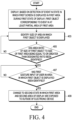
- FIG. 4 is a flow chart illustrating an operation of an electronic device according to various embodiments. The description will be made with reference to FIGS. 4 , 5 , and 6 .
- FIG. 5 illustrates an operation of an electronic device according to various embodiments.
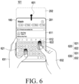
- FIG. 6 illustrates an operation of an electronic device according to various embodiments.
- an electronic device 101 may display, based on detection of an event (for example, an event calling a virtual keyboard, a chat bubble window, or a share menu) in a state in which a screen (for example, a first screen 511 of part (a), a second screen 521 of part (b), or a third screen 531 of part (c) of FIG. 5 ) is displayed in a first area (for example, a first area 201 of FIG.
- an event for example, an event calling a virtual keyboard, a chat bubble window, or a share menu
- a first state for example, a reduced state
- an object for example, a first object 512 of part (a), a second object 522 of part (b), or a third object 532 of part (c) of FIG. 5 ) corresponding to the detected event in at least a partial area of the first area (for example, the first area 201 of FIG. 5 ).
- the electronic device 101 may display, based on detection of an event (for example, an event calling a virtual keyboard) in a state in which the first screen 511 is displayed in at least a part of the first area 201 (for example, an entire area of the first area 201) while the display module 160 is in a reduced state, the first object 512 (for example, a virtual keyboard) corresponding to the detected event in at least a partial area of the first area 201.
- the virtual keyboard may be an object in the form of a keyboard displayed on an execution screen of an application requiring a keyboard input.
- the electronic device 101 may display, based on detection of an event (for example, an event calling a virtual keyboard) in a state in which the first screen 511 is displayed in a first part 513 and a second part 514 of the first area 201 while the electronic device is in a reduced state, the first object 512 (for example, a virtual keyboard) corresponding to the detected event in the second part 514 of the first area 201 while continuously display the first screen 511 having been displayed in the first part 513 of the first area 201. It may be described that in part (a) of FIG. 5 , the first object 512 is displayed while being overlapped onto at least a part of the first screen 511.
- an event for example, an event calling a virtual keyboard
- the electronic device 101 may overlay a first layer and a second layer onto each other and display the same, the first layer including the first screen 511 and the second layer including the first object 512, and the scheme of overlaying layers and displaying the same is described in FIGS. 7 , 8 , 9 , and 10 below.
- the electronic device 101 may display, based on detection of an event (for example, an event calling a chat bubble window) in a state in which the second screen 521 is displayed in at least a part (for example, an entire area of the first area 201) of the first area 201 while the display module 160 is in a reduced state, the second object 522 (for example, a chat bubble window) corresponding to the detected evented in at least a partial area of the first area 201.
- the chat bubble window may be an execution screen of a chatting application provided in a pop-up window scheme.
- the electronic device 101 may display, based on detection of an event (for example, an event calling a chat bubble window) in a state in which the second screen 521 is displayed in a third part 523 and a fourth part 524 of the first area 201 while the electronic device is in a reduced state, the second object 522 (for example, a chat bubble window) corresponding to the detected event in the fourth part 524 of the first area 201 while continuously displaying the second screen 521 having been displayed in the third part 523 of the first area 201. It may be described that in part (b) of FIG. 5 , the second object 522 is displayed while being overlapped onto at least a part of the second screen 521.
- an event for example, an event calling a chat bubble window
- the electronic device 101 may display, based on an event (for example, an event calling a share menu) in a state in which the third screen 531 is displayed in at least a part of the first area 201 (for example, an entire area of the first area 201) while the display module 160 is in a reduced state, the third object 532 (for example, a share menu) corresponding to the detected event in at least a partial area of the first area 201.
- the share menu may be an object used to transfer a content including a file, a link, or text to a cloud server, another electronic device, or another application.
- the electronic device 101 may display, based on detection of an event (for example, an event calling a share menu) in a state in which the third screen 531 is displayed in a fifth part 533 and a sixth part 534 of the first area 201 while the electronic device 101 is in a reduced state, the third object 532 (for example, a share menu) corresponding to the detected event in the sixth part 534 of the first area 201 while continuously displaying the third screen 531 having been displayed in the fifth part 533 of the first area 201. It may be described that the third object 532 is displayed while being overlapped onto at least a part of the third screen 531 in part (c) of FIG. 5 .
- an event for example, an event calling a share menu
- the electronic device 101 may identify the size of an area in which the object (for example, the first object 512 of part (a), the second object 522 of part (b), or the third object 532 of part (c) of FIG. 5 ) corresponding to the detected event (for example, the event calling a virtual keyboard, a chat bubble window, or a share menu) is displayed.
- the object for example, the first object 512 of part (a), the second object 522 of part (b), or the third object 532 of part (c) of FIG. 5
- the detected event for example, the event calling a virtual keyboard, a chat bubble window, or a share menu
- the electronic device 101 may identify the size (for example, the height or the area) of the area (for example, the second part 514 of the first area 201) in which the first object 512 is displayed. For example, the electronic device 101 may identify an area ratio of the area (for example, the second part 514 of the first area 201) of the first object 512 to the area of the first area 201 of the display module 160.
- the electronic device 101 may identify the size (for example, the height or the area) of the area (for example, the fourth part 524 of the first area 201) in which the second object 522 is displayed. For example, the electronic device 101 may identify an area ratio of the area (for example, the fourth part 524 of the first area 201) of the second object 522 to the area of the first area 201 of the display module 160.
- the electronic device 101 may identify the size (for example, the height or the area) of the area (for example, the sixth part 534 of the first area 201) in which the third object 512 is displayed. For example, the electronic device 101 may identify an area ratio of the area (for example, the sixth part 534 of the first area 201) of the third object 532 to the area of the first area 201 of the display module 160.
- the electronic device 101 may perform operation 407, based on identification that the ratio (for example, the height ratio or the area ratio) of the size (for example, the height or the area) of the area in which the object (for example, the first object 512 of part (a), the second object 522 of part (b), or the third object 532 of part (c) of FIG. 5 ) corresponding to the detected event (for example, the event calling a virtual keyboard, a chat bubble window, or a share menu) is displayed to the size (for example, the height or the area) of the first area 201 of the display module 160 is equal to or greater than a designated ratio.
- the ratio for example, the height ratio or the area ratio
- the electronic device 101 may perform operation 409, based on identification of a gesture input (for example, a double touch drag gesture input (for example, 620 of FIG. 6 )) of a user (for example, 630 of FIG. 6 ) in the area in which the object (for example, the first object 512 of part (a), the second object 522 of part (b), or the third object 532 of part (c) of FIG. 5 ) corresponding to the detected event (for example, the event calling a virtual keyboard, a chat bubble window, or a share menu) is displayed.
- a gesture input for example, a double touch drag gesture input (for example, 620 of FIG. 6 )
- a user for example, 630 of FIG. 6
- the object for example, the first object 512 of part (a), the second object 522 of part (b), or the third object 532 of part (c) of FIG. 5
- the detected event for example, the event calling a virtual keyboard, a chat bubble window, or a share menu
- the electronic device 101 may identify a gesture input 620 (for example, the double touch drag gesture input) of a user 630 in the area in which a virtual keyboard 612 corresponding to the event (for example, the event calling a virtual keyboard) detected when the electronic device 101 (for example, the display module 160) is in a reduced state is displayed.
- the electronic device 101 may identify the gesture input 620 (for example, a double touch drag gesture input 621 and 622) input in a designated direction (for example, the direction in which the electronic device 101 (for example, the display module 160) is expanded (for example, direction 601)) starting from a first point and a second point in the area in which the virtual keyboard 612 is displayed.
- the double touch drag gesture input 620 is identified, but to perform operation 409 in another embodiment, a single touch drag gesture input (for example, 621 or 622) may be identified and another designated gesture input may be identified.
- the electronic device 101 may perform operation 409, and when the designated gesture input (for example, 620) is identified in an area other than the area in which the virtual keyboard 612 is displayed, the electronic device may not perform operation 409.
- the electronic device 101 may generate a gesture layer (for example, a layer in which the gesture input (for example, 620) of the user 630 related to expansion or reduction of the electronic device 101 (for example, the display module 160) is detected), thereby controlling the expansion and reduction of the electronic device 101 (for example, the display module 160) according to the gesture input that is input on the gesture layer generated in the area in which the virtual keyboard 612 is displayed, and the gesture layer will be described in FIGS. 7 , 8 , 9 , and 10 below.
- a gesture layer for example, a layer in which the gesture input (for example, 620) of the user 630 related to expansion or reduction of the electronic device 101 (for example, the display module 160) is detected
- the electronic device 101 may control the electronic device 101 to change the state to a second state (for example, an expanded state) in which a first area (for example, 201 of FIG. 6 ) and a second area (for example, 202 of FIG. 6 ) of the display module 160 are exposed to the outside of the electronic device 101.
- the electronic device 101 may control the electronic device to change the state of the electronic device 101 (for example, the display module 160) from the reduced state to the expanded state according to the user's gesture input (for example, 620 of FIG. 6 ) identified in operation 407.
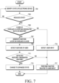
- FIG. 7 is a flow chart illustrating an operation of an electronic device according to various embodiments.
- FIG. 7 is described with reference to FIGS. 8 , 9 , and 10 .
- FIG. 8 illustrates an operation of an electronic device according to various embodiments.
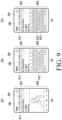
- FIG. 9 illustrates an operation of an electronic device according to various embodiments.
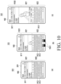
- FIG. 10 illustrates an operation of an electronic device according to various embodiments.
- an electronic device 101 may identify the state of the electronic device 101.
- the electronic device 101 may identify whether the electronic device 101 (for example, a display module 160) is in a reduced state (for example, 211 of FIG. 2 or 311 of FIG. 3 ) or an expanded state (for example, 212 of FIG. 2 or 312 of FIG. 3 ).
- the electronic device 101 may identify the state (for example, the reduced state or the expanded state) of the electronic device 101 by using a sensor module 176 (for example, a hall IC).
- a sensor module 176 for example, a hall IC
- the electronic device 101 may identify whether the size of an overlaid layer (for example, a UI layer) has a designated ratio or greater. For example, according to a result of operation 705, the electronic device may perform operation 707 or operation 715.
- an overlaid layer for example, a UI layer
- overlaying multiple layers may mean, for example, overlapping a second layer onto at least a partial area of a first layer and displaying the same on the display module 160.
- the electronic device 101 may overlay a second layer 812 including a first object (for example, a virtual keyboard) onto at least a partial area of a first layer 811 including a first screen (for example, an execution screen of an Internet application).
- a first object for example, a virtual keyboard
- a first screen for example, an execution screen of an Internet application
- at least a part of the first screen included in the first layer 811 may be hidden by the first object included in the second layer 812 and may not be displayed on a screen.
- the at least a part of the first screen included in the first layer 811 may be hidden by the first object included in the second layer 812, but according to the transparency of the first object (or the second layer 812 including the first object), the at least a part of the first screen and the first object may be overlapped and displayed on the screen.
- the electronic device 101 may overlay, based on detection of an event (for example, an event calling a virtual keyboard), a second layer (for example, a UI layer) including a first object 912 (for example, the virtual keyboard) in at least a partial area (for example, the second part 922 of the first area 201) onto a first layer including the first screen 911 (for example, the execution screen of the social networking service (SNS) application).
- a second layer for example, a UI layer
- the electronic device 101 may identify whether the size of the overlaid second layer (for example, the UI layer) has a designated ratio or greater.
- the electronic device 101 may identify whether the ratio of the size (for example, the height or the area) of the first object 912 (for example, the virtual keyboard) to the size (for example, the height or the area) of the first area 201 is equal to or greater than a designated ratio.
- the electronic device 101 may generate, based on the size of the overlaid layer (for example, the UI layer) having a designated ratio or greater, a layer (for example, a gesture layer) for detecting the user's gesture on the overlaid layer (for example, the UI layer).
- a layer for example, a gesture layer
- a layer for example, a gesture layer (for example, 813 of FIG. 8 )) for generating the user's designated gesture input (for example, a gesture input designated for expansion of the display module 160), separately from a layer (for example, a UI layer (for example, 812 of FIG. 8 )) overlaid onto the screen, and detecting the user's designated gesture input by using the layer (for example, the gesture layer (for example, 813 of FIG. 8 )) for detecting the generated user's designated gesture input is described according to an embodiment.
- the overlaid layer for example, the UI layer (for example, 812 of FIG.
- the electronic device 101 may be a layer including a function of detecting the user's designated gesture input (for example, the gesture input designated for the expansion of the display module 160).
- the electronic device 101 may omit operation 707.
- the electronic device 101 may detect, based on the size of the overlaid layer (for example, the UI layer) having a designated ratio or greater in operation 705, the user's designated gesture input (for example, the gesture input designated for expansion of the display module 160) on the overlaid layer (for example, the UI layer) by using the overlaid layer (for example, the UIlayer) in operation 709.
- the description on the operation of detecting the user's gesture by using the layer for example, the gesture layer (for example, 813 of FIG.
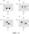
- the electronic device 101 may control, based on detection of the second gesture 1132 (for example, double touch drag down) in the area in which the virtual keyboard 1121 is displayed, the electronic device 101 to change the state of the electronic device 101 (for example, the display module 160) to a reduced state (for example, the reduced state 211 of part (a) of FIG. 2 or the reduced state 311 of part (a) of FIG. 3 ) to an expanded state (for example, the expanded state 212 of part (b) of FIG. 2 or the expanded state 312 of part (b) of FIG. 3 ).
- a reduced state for example, the reduced state 211 of part (a) of FIG. 2 or the reduced state 311 of part (a) of FIG. 3
- an expanded state for example, the expanded state 212 of part (b) of FIG. 2 or the expanded state 312 of part (b) of FIG. 3 .
- the above-described gesture input (for example, the first gesture input 1131, the second gesture input 1132, the third gesture input 1133, or the fourth gesture input 1134) of FIG. 11 is illustrative, and there is no limitation to the type of the gesture input.
- the electronic device 101 may control, based on detection of a gesture input (for example, a long press, a three-finger swipe, or a force touch) in the area in which the virtual keyboard 1121 is displayed, the expansion or the reduction of the electronic device 101 (for example, the display module 160).
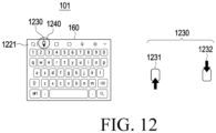
- an electronic device 101 may display, based on detection of an event (for example, an event calling a virtual keyboard, a chat bubble window, or a share menu) in a state in which an execution screen (for example, the first screen 511, the second screen 521, or the third screen 531 of FIG. 5 ) of a first application is displayed in a first area (for example, the first area 210 of FIG. 2 or the first area 310 of FIG. 3 ) of the display module 160, an object (for example, the first object 512, the second object 522, or the third object 532 of FIG. 5 or a virtual keyboard 1221 of FIG.
- an event for example, an event calling a virtual keyboard, a chat bubble window, or a share menu
- the electronic device 101 may control, based on detection of a touch input 1240 to the expansion button 1231 or the reduction button 1232 included in the virtual keyboard 1221 displayed in at least a partial area of the display module 160, expansion or reduction of the electronic device 101 (for example, the display module 160).
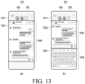
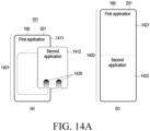
- an electronic device 101 may display, based on detection of a first event (for example, an event calling a chat bubble window) in a state in which a first screen 1311 is displayed in the first area 210 of the display module 160, a first object 1321 (for example, a chat bubble window) corresponding to the first event in at least a partial area 1340 of the first area 201.
- a first event for example, an event calling a chat bubble window
- a first object 1321 for example, a chat bubble window
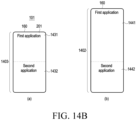
- FIG. 14B illustrates an operation of an electronic device according to various embodiments.
- an electronic device 101 may display a first execution screen 1431 of a first application in a first part of the first area 201 of the display module 160 and display a second execution screen 1432 of a second application in a second part of the first area 201 of the display module 160 while the electronic device 101 (for example, the display module 160) is in a reduced state 1403.
- the electronic device 11 may display the first execution screen 1411 and the second execution screen 1412 in the form of a split window.
- the electronic device 101 may control, based on detection of a designated gesture (for example, double touch drag) in an area corresponding to the second execution screen 1432, the electronic device 101 (for example, the display module 160) to be expanded.
- the electronic device 101 may detect, based on a gesture layer (for example, a layer for detecting a designated gesture input) generated in the area in which the second execution screen 1432 is displayed, a designated gesture input (for example, double touch drag) in an area corresponding to the second execution screen 1432.
- a gesture layer for example, a layer for detecting a designated gesture input
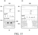
- FIG. 15 illustrates an operation of an electronic device according to various embodiments.
- FIG. 16 illustrates an operation of an electronic device according to various embodiments.
- FIG. 15 illustrates a state in which a screen of the display module 160 is displayed in a first direction (for example, a lengthwise direction or a vertical direction of the electronic device 101) while the electronic device 101 stands in the first direction (for example, the lengthwise direction or the vertical direction of the electronic device 101).
- a first direction for example, a lengthwise direction or a vertical direction of the electronic device 101
- the electronic device 101 stands in the first direction (for example, the lengthwise direction or the vertical direction of the electronic device 101).
- FIG. 16 illustrates a state in which a screen of the display module 160 is displayed in a second direction (for example, a widthwise direction or a horizontal direction of the electronic device 101) while the electronic device 101 stands in the second direction (for example, the widthwise direction or the horizontal direction of the electronic device 101).
- a second direction for example, a widthwise direction or a horizontal direction of the electronic device 101
- the electronic device 101 stands in the second direction (for example, the widthwise direction or the horizontal direction of the electronic device 101).
- FIGS. 15 and 16 illustrate an embodiment in which the electronic device 101 (for example, the display module 160) is expanded or reduced in the second direction (for example, the widthwise direction or the horizontal direction of the electronic device 101) as in FIG. 3 . It can be understood by those skilled in the art that the embodiment described in FIGS. 4 to 14A , and 14B is appliable to the electronic device 101 of FIGS. 15 and 16 .
- an electronic device 101 may display a first screen 1511 on the display module 160 and display a first object 1512 (for example, a virtual keyboard) in at least a partial area of the first screen 1511 in a reduced state 1501.
- the electronic device 101 may detect a designated gesture input 1530 (for example, a double touch drag input) in an area in which the first object 1512 (for example, the virtual keyboard) is displayed.
- the electronic device 101 may control, based on the detected gesture input 1530 (for example, the double touch drag input), expansion or reduction of the electronic device 101 (for example, the display module 160).
- the electronic device 101 may, based on the detected gesture input 1530 (for example, the double touch drag input), change the state of the electronic device 101 (for example, the display module 160) to an expanded state 1502, display, on the expanded display module 160, a second screen 1521 obtained by expanding the first screen 1511, and display, in at least a partial area of the second screen 1521, a second object 1522 (for example, a virtual keyboard split in left and right) obtained by deforming the first object 1512 (for example, the virtual keyboard).
- the detected gesture input 1530 for example, the double touch drag input
- change the state of the electronic device 101 for example, the display module 160
- display on the expanded display module 160
- a second screen 1521 obtained by expanding the first screen 1511
- display in at least a partial area of the second screen 1521, a second object 1522 (for example, a virtual keyboard split in left and right) obtained by deforming the first object 1512 (for example, the virtual keyboard).
- a second object 1522 for example, a virtual keyboard split
- an electronic device 101 may display a third screen 1611 on the display module 160 and display a third object 1612 (for example, a virtual keyboard) in at least a partial area of the third screen 1611 in a reduced state 1601.
- the electronic device 101 may detect a designated gesture input 1630 (for example, a double touch drag input) in an area in which the third object 1612 (for example, the virtual keyboard) is displayed.
- the electronic device 101 may control, based on the detected gesture input 1630 (for example, the double touch drag input), expansion or reduction of the electronic device 101 (for example, the display module 160).
- the electronic device 101 may change, based on the detected gesture input 1630 (for example, the double touch drag input), the state of the electronic device 11 (for example, the display module 160) to an expanded state 1602, display, on the expanded display module 160, a fourth screen 1621 obtained by expanding the third screen 1611, and display, in at least a partial area of the fourth screen 1621, a fourth object 1622 (for example, a virtual keyboard) corresponding to the third object 1621 (for example, the virtual keyboard).
- the width of the area in which the third object 1612 for example, the virtual keyboard
- the electronic device 101 may display the fourth object 1622 (for example, the virtual keyboard) in the same form as that of the third object 1612 (for example, the virtual keyboard) having been displayed in the reduced state 1601.
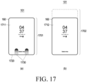
- FIG. 17 illustrates an operation of an electronic device according to various embodiments.
- an electronic device 101 may control expansion or reduction of the electronic device 101 (for example, the display module 160) as a designated gesture input 1730 (for example, a double touch drag input starting from the bottom 1720 of the display module 160 of the electronic device 101) is detected in a screen locked state.
- the screen locked state may be a state in which an input except for a designated input (for example, an input of pressing a designated physical button or a designated touch gesture input) is ignored.
- the electronic device 101 may perform a designated operation corresponding to the designated input if the designated input is detected in the screen locked state, but may not perform any operation for an input other than the designated input.
- FIG. 18 illustrates an operation of an electronic device according to various embodiments.
- an electronic device 101 may display a first screen 1811 on the display module 160 and display a first object 1821 (for example, a virtual keyboard) in at least a partial area of the first screen 1811 in a reduced state 1801.
- the electronic device 101 may control, based on detection of a designated gesture input 1830 in an area in which the first object 1821 (for example, the virtual keyboard) is displayed, expansion or reduction of the electronic device 101 (for example, the display module 160).
- the electronic device 101 may display a screen 1812 obtained by expanding the first screen 1811.
- the electronic device 101 may additionally display at least a partial area of the first screen 1811, having been hidden by the first object 1821.
- the electronic device 101 may change the location of the first object 1821 (for example, the virtual keyboard) to at least a partial area of the screen 1812 and display the same while displaying the screen 1812 obtained by expanding the first screen 1811. For example, referring to parts (a) and (b) of FIG.
- the electronic device 101 may display the first object 1821 by moving the same by a predetermined distance in the expansion direction of the screen, so as to additionally display the screen 1840 having been hidden by the first object 1821 in the reduced state 1821.
- the electronic device 101 may display the first object 1821 in an original location (for example, the location in which the first object 1821 has been displayed in the reduced state) while the electronic device 101 (for example, the display module 160) is in the expanded state 1802.
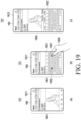
- an electronic device 101 may display a first object 1921 (for example, a virtual keyboard) in at least a partial area on a first screen 1911 displayed on a display module 160 in a reduced state 1901.
- the electronic device 101 may control, based on a touch input 1931 or 1932 (for example, a touch input of inputting text by using a virtual keyboard) to an area in which the first object 1921 (for example, the virtual keyboard) is displayed in the reduced state 1901, the electronic device 101 to change the state of the electronic device 101 (for example, the display module 160) to an expanded state 1902.
- FIG. 20 illustrates an operation of an electronic device according to various embodiments.
- an electronic device may include a display (for example, the display module 160), and a processor 120, wherein the processor is configured to control the display to display a first screen in a first area (for example, the first area 201 of FIG. 2 or the first area 301 of FIG. 3 ) of the display during a first state in which a second area (for example, the second area 202 of FIG. 2 or the second area 302 of FIG.
- a display for example, the display module 160
- the processor 120 is configured to control the display to display a first screen in a first area (for example, the first area 201 of FIG. 2 or the first area 301 of FIG. 3 ) of the display during a first state in which a second area (for example, the second area 202 of FIG. 2 or the second area 302 of FIG.
- the first object may be a pop-up window or a virtual keyboard displayed on the first screen.
- the processor may be configured to overlay a second layer including the first object onto a first layer including the first screen displayed in the first area so as to display the first object while the display is in the first state.
- the processor may be configured to generate, on the second layer including the first object, a gesture layer covering an area corresponding to the at least a partial area in which the first object is displayed, and control, based on detection of the first gesture input on the gesture layer, the electronic device to change the display from the first state to the second state.
- the processor may be configured to remove the gesture layer after changing the display to the second state in response to the first gesture input.
- the processor may be configured to control, based on displaying of a second object related to the first object after displaying the first object, the electronic device to change the display from the first state to the second state in response to the first gesture input of the user in an area in which the first object and the second object are displayed.
- the processor may be configured to display the first object on the first screen while the display is in the first state, and display the first screen by moving, based on the display being changed to the second state, the first screen in a direction in which the display is expanded, so as to display, on the display, at least a partial area of the first screen, having been hidden by the first object in the first state.
- an operation method of an electronic device 101 may include displaying a first screen in a first area (for example, the first area 201 of FIG. 2 or the first area 301 of FIG. 3 ) of a display (for example, the display module 160) of the electronic device during a first state in which a second area (for example, the second area 202 of FIG. 2 or the second area 302 of FIG.
- the displaying of the first object may include overlaying a second layer including the first object onto a first layer including the first screen displayed in the first area so as to display the first object while the display is in the first state.
- the method may further include generate, on the second layer including the first object, a gesture layer covering an area corresponding to the at least a partial area in which the first object is displayed, wherein the changing of the display from the first state to the second state may include change, based on detection of the first gesture input on the gesture layer, the display from the first state to the second state.
- the changing of the display from the first state to the second state may include changing, based on displaying of a second object related to the first object after displaying the first object, the display from the first state to the second state in response to the first gesture input of the user in an area in which the first object and the second object are displayed.
- the machine-readable storage medium may be provided in the form of a non-transitory storage medium.
- non-transitory simply means that the storage medium is a tangible device, and does not include a signal (e.g., an electromagnetic wave), but this term does not differentiate between where data is semi-permanently stored in the storage medium and where the data is temporarily stored in the storage medium.
- a method may be included and provided in a computer program product.
- the computer program product may be traded as a product between a seller and a buyer.
- the computer program product may be distributed in the form of a machine-readable storage medium (e.g., compact disc read only memory (CD-ROM)), or be distributed (e.g., downloaded or uploaded) online via an application store (e.g., PlayStoreTM), or between two user devices (e.g., smart phones) directly. If distributed online, at least part of the computer program product may be temporarily generated or at least temporarily stored in the machine-readable storage medium, such as memory of the manufacturer's server, a server of the application store, or a relay server.
- CD-ROM compact disc read only memory
- an application store e.g., PlayStoreTM
- two user devices e.g., smart phones
- operations performed by the module, the program, or another component may be carried out sequentially, in parallel, repeatedly, or heuristically, or one or more of the operations may be executed in a different order or omitted, or one or more other operations may be added.
Landscapes
- Engineering & Computer Science (AREA)
- Theoretical Computer Science (AREA)
- General Engineering & Computer Science (AREA)
- Physics & Mathematics (AREA)
- General Physics & Mathematics (AREA)
- Human Computer Interaction (AREA)
- Computer Hardware Design (AREA)
- Mathematical Physics (AREA)
- User Interface Of Digital Computer (AREA)
Applications Claiming Priority (3)
| Application Number | Priority Date | Filing Date | Title |
|---|---|---|---|
| KR20210134916 | 2021-10-12 | ||
| KR1020220019331A KR20230052186A (ko) | 2021-10-12 | 2022-02-15 | 전자 장치의 디스플레이를 확장하는 방법 및 이를 지원하는 전자 장치 |
| PCT/KR2022/015400 WO2023063720A1 (ko) | 2021-10-12 | 2022-10-12 | 전자 장치의 디스플레이를 확장하는 방법 및 이를 지원하는 전자 장치 |
Publications (3)
| Publication Number | Publication Date |
|---|---|
| EP4394570A1 true EP4394570A1 (de) | 2024-07-03 |
| EP4394570A4 EP4394570A4 (de) | 2024-12-25 |
| EP4394570B1 EP4394570B1 (de) | 2026-02-18 |
Family
ID=85987522
Family Applications (1)
| Application Number | Title | Priority Date | Filing Date |
|---|---|---|---|
| EP22881347.3A Active EP4394570B1 (de) | 2021-10-12 | 2022-10-12 | Verfahren zur erweiterung der anzeige einer elektronischen vorrichtung und elektronische vorrichtung zur unterstützung davon |
Country Status (3)
| Country | Link |
|---|---|
| US (1) | US12283213B2 (de) |
| EP (1) | EP4394570B1 (de) |
| WO (1) | WO2023063720A1 (de) |
Families Citing this family (3)
| Publication number | Priority date | Publication date | Assignee | Title |
|---|---|---|---|---|
| EP4235493A4 (de) * | 2021-04-22 | 2024-09-18 | Samsung Electronics Co., Ltd. | Elektronische vorrichtung zur überprüfung der verbindung eines verbinders und betriebsverfahren dafür |
| DE102021120849B3 (de) * | 2021-08-11 | 2022-12-08 | Audi Aktiengesellschaft | Anzeigevorrichtung für ein Kraftfahrzeug, Verfahren zum Anzeigen eines Anzeigeinhalts auf einem ausfahrbaren Bildschirm und Kraftfahrzeug mit einer Anzeigevorrichtung |
| US20260084530A1 (en) * | 2024-09-24 | 2026-03-26 | GM Global Technology Operations LLC | Vehicle deployable control for automated vehicles |
Family Cites Families (16)
| Publication number | Priority date | Publication date | Assignee | Title |
|---|---|---|---|---|
| KR102305508B1 (ko) | 2015-02-25 | 2021-09-28 | 삼성디스플레이 주식회사 | 폴더블 디스플레이 장치 |
| KR20160123620A (ko) * | 2015-04-16 | 2016-10-26 | 삼성전자주식회사 | 디스플레이 장치 및 디스플레이 방법 |
| KR20160139287A (ko) | 2015-05-27 | 2016-12-07 | 엘지전자 주식회사 | 변형 가능한 디스플레이 장치 및 그의 동작 방법 |
| EP3385831A1 (de) * | 2017-04-04 | 2018-10-10 | Lg Electronics Inc. | Mobiles endgerät |
| KR102262962B1 (ko) * | 2018-02-14 | 2021-06-10 | 삼성전자주식회사 | 어플리케이션과 관련된 기능 또는 콘텐트를 제공하는 방법 및 이를 수행하는 전자 장치 |
| KR102266152B1 (ko) | 2018-02-22 | 2021-06-17 | 삼성전자주식회사 | 디스플레이 영역의 크기 변경이 가능한 플렉시블 디스플레이를 포함하는 전자 장치 및 그 제어 방법 |
| KR102640672B1 (ko) | 2019-09-06 | 2024-02-28 | 엘지전자 주식회사 | 이동 단말기 및 그 제어 방법 |
| US12055981B2 (en) | 2019-10-28 | 2024-08-06 | Lg Electronics Inc. | Electronic device including display changing in size and control method therefor |
| WO2021100932A1 (ko) | 2019-11-22 | 2021-05-27 | 엘지전자 주식회사 | 디스플레이의 크기를 제어하는 전자 장치 및 그 제어 방법 |
| WO2021107225A1 (ko) | 2019-11-29 | 2021-06-03 | 엘지전자 주식회사 | 디스플레이의 크기를 제어하는 전자 장치 및 그 제어 방법 |
| EP4058868B1 (de) * | 2020-02-14 | 2024-04-10 | Huawei Technologies Co., Ltd. | Walzgesten und verhinderung von fehlberührungen an walzvorrichtungen |
| US11908363B2 (en) * | 2020-02-14 | 2024-02-20 | Huawei Technologies Co., Ltd. | Self-adaptive display aspect ratio adjuster and gesture on rolling devices |
| KR102256042B1 (ko) * | 2020-10-13 | 2021-05-25 | 삼성전자 주식회사 | 입력을 유도하는 전자 장치 및 방법. |
| KR102256681B1 (ko) | 2020-10-19 | 2021-05-26 | 삼성전자 주식회사 | 화면 제어 방법 및 그 전자 장치 |
| KR102247663B1 (ko) | 2020-11-06 | 2021-05-03 | 삼성전자 주식회사 | 디스플레이의 제어 방법 및 이를 지원하는 전자 장치 |
| KR102256292B1 (ko) | 2020-11-26 | 2021-05-26 | 삼성전자 주식회사 | 확장이 가능한 디스플레이를 이용하여 멀티 윈도우를 제공하는 전자 장치 |
-
2022
- 2022-10-12 EP EP22881347.3A patent/EP4394570B1/de active Active
- 2022-10-12 WO PCT/KR2022/015400 patent/WO2023063720A1/ko not_active Ceased
-
2024
- 2024-03-27 US US18/618,106 patent/US12283213B2/en active Active
Also Published As
| Publication number | Publication date |
|---|---|
| US12283213B2 (en) | 2025-04-22 |
| US20240242648A1 (en) | 2024-07-18 |
| WO2023063720A1 (ko) | 2023-04-20 |
| EP4394570B1 (de) | 2026-02-18 |
| EP4394570A4 (de) | 2024-12-25 |
Similar Documents
| Publication | Publication Date | Title |
|---|---|---|
| US12284301B2 (en) | Slidable electronic device and operating method thereof | |
| US12032815B2 (en) | Slidable electronic device and control method therefor | |
| US12395584B2 (en) | Electronic device for providing both shared screen and private screen, and control method therefor | |
| US11366563B2 (en) | Electronic device and method for inducing input | |
| EP4138037B1 (de) | Mehrfensterbilderfassungsverfahren und elektronische vorrichtung dafür | |
| US12283213B2 (en) | Method for expanding display of electronic device, and electronic device for supporting same | |
| US20240281126A1 (en) | Electronic device changing configuration of screen according to change in size of at least one icon and method for controlling the same | |
| US12596403B2 (en) | Slidable electronic device and control method thereof | |
| US12008214B2 (en) | Method for restoring home screen and electronic device applying the same | |
| US12431051B2 (en) | Electronic device having flexible display | |
| US20230308880A1 (en) | Electronic device and method for operating electronic device | |
| US20230247130A1 (en) | Method for providing screen by using flexible display, and electronic device supporting same | |
| US12340608B2 (en) | Electronic device for processing handwriting input, and operation method therefor | |
| EP4394568A1 (de) | Verfahren zur anzeige eines ausführungsbildschirms einer anwendung und elektronische vorrichtung zur unterstützung davon | |
| US20220164093A1 (en) | Electronic device with expandable display | |
| US12026339B2 (en) | Electronic device, and method for displaying content in electronic device | |
| EP4589416A1 (de) | Elektronische vorrichtung, die die konfiguration eines bildschirms als reaktion auf die änderung der grösse von mindestens einem symbol ändert, und steuerungsverfahren dafür | |
| EP4465158A1 (de) | Elektronische vorrichtung und verfahren zur anzeige von berührungseingabe oder schwebeeingabe auf basis von änderungen im anzeigebereich einer rollbaren anzeige | |
| EP4647887A1 (de) | Elektronische vorrichtung zur verarbeitung eines bildes und verfahren zum betrieb davon | |
| US20260126760A1 (en) | Method for recommending setting of screen and electronic device supporting thereof | |
| US20260023480A1 (en) | Electronic device for controlling display of execution screens, operation method thereof, and recording medium | |
| US20250124627A1 (en) | First electronic device including artificial intelligence model, method for operating the same, and second electronic device including artificial intelligence model | |
| US20260086704A1 (en) | Electronic device supporting multi-window, and control method thereof | |
| US20240038112A1 (en) | Electronic device and method for displaying screen through flexible display | |
| US20250264983A1 (en) | Electronic device and method for extending exposed area of display |
Legal Events
| Date | Code | Title | Description |
|---|---|---|---|
| STAA | Information on the status of an ep patent application or granted ep patent |
Free format text: STATUS: THE INTERNATIONAL PUBLICATION HAS BEEN MADE |
|
| PUAI | Public reference made under article 153(3) epc to a published international application that has entered the european phase |
Free format text: ORIGINAL CODE: 0009012 |
|
| STAA | Information on the status of an ep patent application or granted ep patent |
Free format text: STATUS: REQUEST FOR EXAMINATION WAS MADE |
|
| 17P | Request for examination filed |
Effective date: 20240328 |
|
| AK | Designated contracting states |
Kind code of ref document: A1 Designated state(s): AL AT BE BG CH CY CZ DE DK EE ES FI FR GB GR HR HU IE IS IT LI LT LU LV MC ME MK MT NL NO PL PT RO RS SE SI SK SM TR |
|
| A4 | Supplementary search report drawn up and despatched |
Effective date: 20241126 |
|
| RIC1 | Information provided on ipc code assigned before grant |
Ipc: G06F 3/04886 20220101ALI20241120BHEP Ipc: G06F 3/0488 20220101ALI20241120BHEP Ipc: G06F 3/0481 20220101ALI20241120BHEP Ipc: G06F 1/16 20060101ALI20241120BHEP Ipc: G06F 3/04883 20220101ALI20241120BHEP Ipc: G06F 3/0484 20220101AFI20241120BHEP |
|
| DAV | Request for validation of the european patent (deleted) | ||
| DAX | Request for extension of the european patent (deleted) | ||
| GRAP | Despatch of communication of intention to grant a patent |
Free format text: ORIGINAL CODE: EPIDOSNIGR1 |
|
| STAA | Information on the status of an ep patent application or granted ep patent |
Free format text: STATUS: GRANT OF PATENT IS INTENDED |
|
| RIC1 | Information provided on ipc code assigned before grant |
Ipc: G06F 3/0484 20220101AFI20250903BHEP Ipc: G06F 3/04883 20220101ALI20250903BHEP Ipc: G06F 1/16 20060101ALI20250903BHEP Ipc: G06F 3/0481 20220101ALI20250903BHEP Ipc: G06F 3/0488 20220101ALI20250903BHEP Ipc: G06F 3/04886 20220101ALI20250903BHEP |
|
| INTG | Intention to grant announced |
Effective date: 20250915 |
|
| GRAS | Grant fee paid |
Free format text: ORIGINAL CODE: EPIDOSNIGR3 |
|
| GRAA | (expected) grant |
Free format text: ORIGINAL CODE: 0009210 |
|
| STAA | Information on the status of an ep patent application or granted ep patent |
Free format text: STATUS: THE PATENT HAS BEEN GRANTED |
|
| AK | Designated contracting states |
Kind code of ref document: B1 Designated state(s): AL AT BE BG CH CY CZ DE DK EE ES FI FR GB GR HR HU IE IS IT LI LT LU LV MC ME MK MT NL NO PL PT RO RS SE SI SK SM TR |
|
| REG | Reference to a national code |
Ref country code: CH Ref legal event code: F10 Free format text: ST27 STATUS EVENT CODE: U-0-0-F10-F00 (AS PROVIDED BY THE NATIONAL OFFICE) Effective date: 20260218 Ref country code: GB Ref legal event code: FG4D |
|
| REG | Reference to a national code |
Ref country code: IE Ref legal event code: FG4D |
|
| REG | Reference to a national code |
Ref country code: DE Ref legal event code: R096 Ref document number: 602022030857 Country of ref document: DE |