EP4394574A1 - Dispositif et système de stockage et procédé de stockage de données - Google Patents
Dispositif et système de stockage et procédé de stockage de données Download PDFInfo
- Publication number
- EP4394574A1 EP4394574A1 EP22871544.7A EP22871544A EP4394574A1 EP 4394574 A1 EP4394574 A1 EP 4394574A1 EP 22871544 A EP22871544 A EP 22871544A EP 4394574 A1 EP4394574 A1 EP 4394574A1
- Authority
- EP
- European Patent Office
- Prior art keywords
- storage
- data
- storage unit
- level
- storage device
- Prior art date
- Legal status (The legal status is an assumption and is not a legal conclusion. Google has not performed a legal analysis and makes no representation as to the accuracy of the status listed.)
- Pending
Links
Images

Classifications
-
- G—PHYSICS
- G06—COMPUTING OR CALCULATING; COUNTING
- G06F—ELECTRIC DIGITAL DATA PROCESSING
- G06F3/00—Input arrangements for transferring data to be processed into a form capable of being handled by the computer; Output arrangements for transferring data from processing unit to output unit, e.g. interface arrangements
- G06F3/06—Digital input from, or digital output to, record carriers, e.g. RAID, emulated record carriers or networked record carriers
-
- G—PHYSICS
- G06—COMPUTING OR CALCULATING; COUNTING
- G06F—ELECTRIC DIGITAL DATA PROCESSING
- G06F3/00—Input arrangements for transferring data to be processed into a form capable of being handled by the computer; Output arrangements for transferring data from processing unit to output unit, e.g. interface arrangements
- G06F3/06—Digital input from, or digital output to, record carriers, e.g. RAID, emulated record carriers or networked record carriers
- G06F3/0601—Interfaces specially adapted for storage systems
- G06F3/0602—Interfaces specially adapted for storage systems specifically adapted to achieve a particular effect
- G06F3/0614—Improving the reliability of storage systems
- G06F3/0619—Improving the reliability of storage systems in relation to data integrity, e.g. data losses, bit errors
-
- G—PHYSICS
- G06—COMPUTING OR CALCULATING; COUNTING
- G06F—ELECTRIC DIGITAL DATA PROCESSING
- G06F11/00—Error detection; Error correction; Monitoring
- G06F11/07—Responding to the occurrence of a fault, e.g. fault tolerance
- G06F11/14—Error detection or correction of the data by redundancy in operations
-
- G—PHYSICS
- G06—COMPUTING OR CALCULATING; COUNTING
- G06F—ELECTRIC DIGITAL DATA PROCESSING
- G06F12/00—Accessing, addressing or allocating within memory systems or architectures
- G06F12/02—Addressing or allocation; Relocation
- G06F12/0223—User address space allocation, e.g. contiguous or non contiguous base addressing
- G06F12/023—Free address space management
- G06F12/0238—Memory management in non-volatile memory, e.g. resistive RAM or ferroelectric memory
- G06F12/0246—Memory management in non-volatile memory, e.g. resistive RAM or ferroelectric memory in block erasable memory, e.g. flash memory
-
- G—PHYSICS
- G06—COMPUTING OR CALCULATING; COUNTING
- G06F—ELECTRIC DIGITAL DATA PROCESSING
- G06F3/00—Input arrangements for transferring data to be processed into a form capable of being handled by the computer; Output arrangements for transferring data from processing unit to output unit, e.g. interface arrangements
- G06F3/06—Digital input from, or digital output to, record carriers, e.g. RAID, emulated record carriers or networked record carriers
- G06F3/0601—Interfaces specially adapted for storage systems
- G06F3/0628—Interfaces specially adapted for storage systems making use of a particular technique
- G06F3/0655—Vertical data movement, i.e. input-output transfer; data movement between one or more hosts and one or more storage devices
- G06F3/0659—Command handling arrangements, e.g. command buffers, queues, command scheduling
-
- G—PHYSICS
- G06—COMPUTING OR CALCULATING; COUNTING
- G06F—ELECTRIC DIGITAL DATA PROCESSING
- G06F3/00—Input arrangements for transferring data to be processed into a form capable of being handled by the computer; Output arrangements for transferring data from processing unit to output unit, e.g. interface arrangements
- G06F3/06—Digital input from, or digital output to, record carriers, e.g. RAID, emulated record carriers or networked record carriers
- G06F3/0601—Interfaces specially adapted for storage systems
- G06F3/0668—Interfaces specially adapted for storage systems adopting a particular infrastructure
- G06F3/0671—In-line storage system
- G06F3/0683—Plurality of storage devices
-
- G—PHYSICS
- G06—COMPUTING OR CALCULATING; COUNTING
- G06F—ELECTRIC DIGITAL DATA PROCESSING
- G06F2212/00—Indexing scheme relating to accessing, addressing or allocation within memory systems or architectures
- G06F2212/72—Details relating to flash memory management
- G06F2212/7203—Temporary buffering, e.g. using volatile buffer or dedicated buffer blocks
-
- G—PHYSICS
- G06—COMPUTING OR CALCULATING; COUNTING
- G06F—ELECTRIC DIGITAL DATA PROCESSING
- G06F2212/00—Indexing scheme relating to accessing, addressing or allocation within memory systems or architectures
- G06F2212/72—Details relating to flash memory management
- G06F2212/7204—Capacity control, e.g. partitioning, end-of-life degradation
Definitions
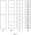
- a storage system converts a QLC for data storage into an SLC in a hard disk, or converts an SLC for data storage into a QLC in a hard disk.
- the SLC occupies less storage capacity.
- the SLC used for read/write acceleration in the hard disk completely disappears. As a result, read/write performance of the storage system is affected.
- This application provides a storage device, a data storage method, and a storage system, to resolve a problem that hardware acceleration cannot be performed in the storage device.
- the data storage method further includes: The control unit obtains a first read request used to request the target data, and reads the target data from a first-level storage unit indicated by a first identifier included in the first read request.
- the first identifier indicates that the target data is stored in the first-level storage unit of the data area.
- the storage device may read the first data from a QLC indicated by a QLC identifier (identifier, ID) included in the first read request.
- the QLC ID indicates that the first data is stored in a QLC of the data area.
- the control unit may parse the QLC ID to determine a physical chunk (chunk) in which the first data is stored.
- the data storage method further includes: The control unit obtains a second read request used to request the target data, and reads the target data from a second-level storage unit indicated by a second identifier included in the second read request.
- the second identifier indicates that the target data is stored in the second-level storage unit of the data area.
- the storage device may read the second data from an SLC indicated by an SLC ID included in the second read request.
- the SLC ID indicates that the first data is stored in an SLC of the data area.
- the control unit may parse the SLC ID to determine a physical chunk (chunk) in which the second data is stored.
- the storage device may determine a read location or a write location of the target data based on a storage unit ID (or referred to as a data flow ID) included in a read request or a write request. This improves a data read/write speed of the storage device, so that data access performance of the storage device is improved.
- a storage unit ID or referred to as a data flow ID
- the data storage method further includes: For each first-level storage unit included in the first storage unit set, the control unit collects statistics on a quantity of erase times of the first-level storage unit, and performs wear protection on a first-level storage unit whose quantity of erase times reaches a first threshold.
- control unit migrates data stored in the first-level storage unit whose quantity of erase times reaches the first threshold to a first-level storage unit whose quantity of erase times does not reach the first threshold.
- Data is migrated between storage units of a same type in the storage device, to balance service life of a plurality of storage units that are of a same type, so that load balancing of the storage units in the storage device is achieved, and overall service life of the storage device is extended.
- this application provides a storage system, including a controller and the storage device according to any one of the first aspect or the second aspect.
- the controller is configured to obtain target data, and send the target data to the storage device.
- the storage device is configured to temporarily store the target data in a hot spare area included in the storage device, and write, under a specific condition, the target data from the hot spare area into a data area included in the storage device.
- the storage system may further implement a function in any one of the implementations of the first aspect and the second aspect.
- a function in any one of the implementations of the first aspect and the second aspect.
- the data storage apparatus has a function of implementing behavior in the instance of any one of the first aspect and the second aspect.
- the function may be implemented by hardware, or may be implemented by hardware executing corresponding software.
- the hardware or the software includes one or more modules corresponding to the foregoing function.
- FIG. 1 is a schematic diagram of a data storage system according to this application.
- the data storage system includes a computing device 100 and a storage system 120.
- a user accesses data by using applications.
- a computer running these applications may be referred to as a "computing device".
- the computing device 100 may be a physical machine, or may be a virtual machine.
- the physical computing device includes but is not limited to a desktop computer, a server, a notebook computer, and a mobile device.
- the computing device 100 accesses the storage system 120 through a network to access data
- the network may include a switch 110.
- the processor 1212 sends, through the back-end port, the data stored in the memory 1213 to at least one of the hard disk drive 1211, a hard disk drive 1222, a solid state drive (solid state drive, SSD) 1223, or another hard disk 1224 for persistent storage.
- the hard disk drive 1211 a hard disk drive 1222
- a solid state drive solid state drive (solid state drive, SSD) 1223
- another hard disk 1224 for persistent storage.
- the memory 1213 is an internal memory that directly exchanges data with the processor.
- the memory 1213 can read and write the data at a fast speed at any time, and serves as a temporary data memory of an operating system or another running program.
- the memory includes at least two types of memories.
- the memory may be a random access memory, or may be a read-only memory (read-only memory, ROM).
- the random access memory is a DRAM or an SCM.
- the DRAM is a semiconductor memory, which is a volatile memory (volatile memory) device like most random access memories (random access memories, RAMs).
- the disk enclosure 122 includes a control unit 1225 and a plurality of hard disks.
- the control unit 1225 may have a plurality of forms.
- the disk enclosure 122 belongs to a smart disk enclosure.
- the control unit 1225 includes a CPU and a memory.
- the CPU is configured to perform operations such as address translation, data reading and writing, and the like.
- the memory is configured to temporarily store data that is to be written into the hard disk, or data this is read from the hard disk and that is to be sent to the controller.
- the control unit 1225 is a programmable electronic component, for example, a data processing unit (data processing unit, DPU).
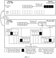
- the data area and the hot spare area use different logical address space.
- the hard disk in the storage device 300 provides first-level storage units for the first storage unit set and the second storage unit set simultaneously.
- the hard disk 321 is divided into four parts.
- a first-level storage unit of one part is configured to provide storage space for the hot spare area, and first-level storage units of the other three parts are configured to provide storage space for the data area.
- the first storage unit set includes a plurality of first storage units (small white squares shown in a physical disk in FIG. 3 ), and the plurality of first storage units may provide logical address space used for storage for the data area in the storage resource pool.
- the control unit 310 in the storage device 300 reports storage space information to the controller.
- the controller constructs a storage resource pool based on the storage space information, user setting information, and the like, and configures areas such as metadata space, a data area, hot spare space (or referred to as a hot spare area), and reserved space.
- the controller included in the storage system uses part of the hot spare area as a read cache area. For example, the controller uses one quarter of the hot spare area as the read cache area, and an SLC obtained by converting a QLC provides storage space for the read cache area.
- control unit 310 may convert the first-level storage units included in the second storage unit set into a plurality of second-level storage units.
- a data read/write speed of the second-level storage unit is greater than a data read/write speed of the first-level storage unit. That is, a data read/write speed of the storage device in an initialized state is consistent with that of the first-level storage unit.
- a data read/write speed of a data access service provided externally by the storage device is consistent with that of the second-level storage unit, so that the data read/write speed of the storage device is improved, and data access performance of the storage device is further improved.
- FIG. 4 is a flowchart of a data storage method according to this application.
- the storage device 300 provides a storage resource pool for a host or a computing device.
- the storage resource pool includes a data area and a hot spare area.
- the data storage method includes the following steps.
- the control unit 310 stores obtained target data in the hot spare area.
- a data read/write speed of the first-level storage unit is lower than a data read/write speed of the second-level storage unit.
- a storage function of the hot spare area is provided by the second-level storage unit, and a storage function of the data area is provided by the first-level storage unit. Therefore, a data read/write speed of the hot spare area is higher than a data read/write speed of the data area, and the hot spare area in the storage device 300 is used as a cache of the data area. This improves performance of reading/writing external data (for example, the foregoing target data) of the storage device 300.
- the control unit 310 writes the target data stored in the hot spare area into the data area under a specific condition.
- the specific condition may be that a data amount stored in the hot spare area reaches a threshold, for example, 100 megabytes (megabytes, MB) or 20 MB.
- a threshold for example, 100 megabytes (megabytes, MB) or 20 MB.
- the specific condition may be that an available capacity of the hot spare area is less than a capacity threshold, for example, 10 MB, 5 MB, or 2 MB.
- the hot spare area is used as the cache of the data area. Because a quantity of bits that can be stored in a second-level storage unit corresponding to the hot spare area is less than a quantity of bits that can be stored in a first-level storage unit corresponding to the data area, data read/write performance of the hot spare area is higher than data read/write performance of the data area.
- the storage device temporarily stores the target data in the hot spare area.
- the storage system preferentially accesses the hot spare area, so that when the storage device provides a data access service externally, the data read/write speed of the storage device is consistent with the data read/write speed of the hot spare area, and data access efficiency of the storage device is improved. Because the hot spare area always exists in the storage device, a data caching function provided by the hot spare area does not disappear. In this way, a problem that a data read/write speed decreases caused by disappearance of an SLC in a common technology is avoided.
- the storage device writes (or referred to as migrates) the target data stored in the hot spare area into the data area.
- the data area of the storage device performs persistent storage on the target data, so that the storage device may be divided into a cache (hot spare area) and persistent storage (data area), to implement hardware acceleration inside the storage device and improve data access performance of the storage device.
- the hot spare area is provided by the storage device, and the hot spare area may be used as the cache of the storage device. Therefore, in a hardware acceleration scenario, there is no need to add an additional high-performance storage medium used for caching to the storage device. This reduces costs of implementing hardware acceleration by the storage device.
- the storage device 300 may write the target data into different storage units based on cold and hot information of the target data.
- the cold and hot information is a quantity of times that the target data is accessed in a unit time, or is referred to as an access frequency of the target data. If the access frequency of the target data is higher than a frequency threshold, the target data is hot data.
- a write request may carry an identifier that indicates the cold and hot information of the target data, for example, the identifier is a data flow ID.
- the data flow ID not only indicates cold and hotness of the target data, but also indicates a type of a storage unit in which the target data is to be stored in the storage device 300.
- the storage device 300 may quickly access the target data based on the data flow ID. In this way, data access efficiency of the storage device is improved.
- the data flow ID may be a QLC ID.
- the storage device 300 may write the target data into a QLC in the storage device 300 based on the QLC ID included in the write request.
- the QLC may be a first-level storage unit that provides storage space for the data area.
- the data flow ID may be an SLC ID.
- the storage device 300 may write the target data into an SLC in the storage device 300 based on the SLC ID included in the write request.
- the SLC may be a second-level storage unit that provides storage space for the hot spare area.
- the QLC ID and the SLC ID are merely examples provided for describing the data flow ID.
- the data flow ID may be generated based on cold and hot information of the to-be-written data by a controller (the controller shown in FIG. 1 ) in a storage system in which the storage device is located, or may be specified by a client (for example, a host, or another computing device that communicates with the storage system or the storage device).
- a read request may carry the foregoing data flow ID.
- the storage device 300 may read the target data from a QLC indicated by a QLC ID included in the first read request.
- the QLC ID indicates that the target data is stored in a QLC of the data area.
- the control unit 310 may parse the QLC ID to determine a physical chunk (chunk) in which the target data is stored.
- the chunk is a first-level storage unit (a small white square in the physical disk 300B) that provides storage space for the data area in FIG. 4 .
- the storage device 300 may read the target data from an SLC indicated by an SLC ID included in the second read request.
- the SLC ID indicates that the target data is stored in an SLC of the data area.
- the control unit 310 may parse the SLC ID to determine a chunk in which the target data is stored.
- the chunk is a second-level storage unit (a small square filled with spots in the physical disk 300B) that provides storage space for the hot spare area in FIG. 4 .
- the storage device may determine a read location or a write location of the target data based on the data flow ID included in the read request or the write request. This improves the data read/write speed of the storage device, so that data access performance of the storage device is improved.
- the storage device 300 may further collects statistics on a quantity of erase times of the first-level storage unit, and performs wear protection on a first-level storage unit whose quantity of erase times reaches a first threshold.
- the wear protection is storage unit conversion.
- the control unit converts the first-level storage unit whose quantity of erase times reaches the first threshold into the second-level storage unit.
- the storage device converts the first-level storage unit into the second-level storage unit. This may improve a quantity of remaining P/E times of the second storage unit obtained through conversion in the storage device, so that service life of the storage device is extended and wear leveling of the storage device is implemented.
- control unit may further convert a plurality of second-level storage units into first-level storage units based on usage of each storage unit in the storage device.
- the control unit converts the second-level storage unit (for example, an SLC) that provides storage space for the hot spare area into the first-level storage unit (for example, a QLC), and uses the first-level storage unit to recover data in the faulty hard disk. This ensures data reliability of the storage device.
- the second-level storage unit for example, an SLC
- the first-level storage unit for example, a QLC
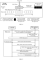
- the storage management process includes a data access process and a troubleshooting process.
- the data access process includes the following steps S510 to S530.
- the disk enclosure 122 performs storage unit conversion based on the data flow ID.
- the disk enclosure 122 may convert an SLC that provides storage space for the hot spare area into a QLC.
- the disk enclosure 122 may convert a QLC that provides storage space for the hot spare area into an SLC, to improve an overall read/write speed of the disk enclosure 122, so that data access performance of the storage system 120 is improved.
- the troubleshooting process provided in this embodiment includes the following steps S541 to S545.
- the fault information indicates that a faulty disk exists in the disk enclosure 122.
- the disk enclosure 122 clears read cache data in the hot spare area.
- the read cache data is the data stored in the SLC that provides storage space for the hot spare area. After S543, the disk enclosure 122 may return, to the controller, a response indicating that the read cache data is cleared.
- the storage system and the storage device include corresponding hardware structures and/or software modules for performing each function.
- a person skilled in the art should be easily aware that, in combination with the units and the method steps in the examples described in embodiments disclosed in this application, this application can be implemented by using hardware or a combination of hardware and computer software. Whether a function is performed by using hardware or hardware driven by computer software depends on particular application scenarios and design constraints of the technical solutions.
- the data storage method may be implemented by a data storage apparatus, for example, the data storage apparatus includes a communication module and a processing module.
- the communication module is configured to receive or send target data.
- the processing module is configured to determine a storage location of the target data, implement conversion of a storage module, and the like.
- the data storage method when the data storage method provided in this application is implemented by hardware, the data storage method may be performed by the disk enclosure 122 or the storage system 120 shown in FIG. 1 , or may be performed by another storage system in the content described in FIG. 1 .
- a processor in embodiments of this application may be a CPU, an NPU, or a GPU, or may be another general purpose processor, a digital signal processor (digital signal processor, DSP), an application-specific integrated circuit (application-specific integrated circuit, ASIC), a field programmable gate array (field programmable gate array, FPGA), or another programmable logic device, a transistor logic device, a hardware component, or any combination thereof.
- the general purpose processor may be a microprocessor or any regular processor.
- the method steps in embodiments of this application may be implemented in a hardware manner, or may be implemented in a manner of executing software instructions by the processor.
- the software instructions may include a corresponding software module.
- the software module may be stored in a RAM, a flash, a ROM, a PROM, an EPROM, an electrically erasable programmable read-only memory (electrically EPROM, EEPROM), a register, a hard disk, a removable hard disk, a CD-ROM, or a storage medium of any other form well-known in this field.
- a storage medium is coupled to a processor, so that the processor can read information from the storage medium and write information into the storage medium.
- the storage medium may be a component of the processor.
- the processor and the storage medium may be disposed in an ASIC.
- the ASIC may be located in a network device or a terminal device.
- the processor and the storage medium may alternatively exist as discrete components in the network device or the terminal device.
Landscapes
- Engineering & Computer Science (AREA)
- Theoretical Computer Science (AREA)
- Physics & Mathematics (AREA)
- General Engineering & Computer Science (AREA)
- General Physics & Mathematics (AREA)
- Human Computer Interaction (AREA)
- Computer Security & Cryptography (AREA)
- Quality & Reliability (AREA)
- Information Retrieval, Db Structures And Fs Structures Therefor (AREA)
- Techniques For Improving Reliability Of Storages (AREA)
Applications Claiming Priority (2)
| Application Number | Priority Date | Filing Date | Title |
|---|---|---|---|
| CN202111115207.XA CN115857790A (zh) | 2021-09-23 | 2021-09-23 | 一种存储设备、数据存储方法及存储系统 |
| PCT/CN2022/103741 WO2023045483A1 (fr) | 2021-09-23 | 2022-07-04 | Dispositif et système de stockage et procédé de stockage de données |
Publications (2)
| Publication Number | Publication Date |
|---|---|
| EP4394574A1 true EP4394574A1 (fr) | 2024-07-03 |
| EP4394574A4 EP4394574A4 (fr) | 2024-12-25 |
Family
ID=85652284
Family Applications (1)
| Application Number | Title | Priority Date | Filing Date |
|---|---|---|---|
| EP22871544.7A Pending EP4394574A4 (fr) | 2021-09-23 | 2022-07-04 | Dispositif et système de stockage et procédé de stockage de données |
Country Status (4)
| Country | Link |
|---|---|
| US (1) | US20240231645A1 (fr) |
| EP (1) | EP4394574A4 (fr) |
| CN (1) | CN115857790A (fr) |
| WO (1) | WO2023045483A1 (fr) |
Families Citing this family (4)
| Publication number | Priority date | Publication date | Assignee | Title |
|---|---|---|---|---|
| CN116069266B (zh) * | 2023-04-06 | 2023-06-20 | 苏州浪潮智能科技有限公司 | 磁盘漫游控制方法、装置、设备及计算机可读存储介质 |
| CN116149574B (zh) * | 2023-04-20 | 2023-07-14 | 苏州浪潮智能科技有限公司 | Raid阵列的管理方法、装置、raid卡及存储介质 |
| US12596650B2 (en) | 2023-09-29 | 2026-04-07 | Advanced Micro Devices, Inc. | Preemptive flushing of processing-in-memory data structures |
| CN119937896B (zh) * | 2023-11-02 | 2026-01-09 | 上海江波龙数字技术有限公司 | 一种存储设备的控制方法、存储设备及电子设备 |
Family Cites Families (13)
| Publication number | Priority date | Publication date | Assignee | Title |
|---|---|---|---|---|
| US20100017649A1 (en) * | 2008-07-19 | 2010-01-21 | Nanostar Corporation | Data storage system with wear-leveling algorithm |
| US8886990B2 (en) * | 2011-01-27 | 2014-11-11 | Apple Inc. | Block management schemes in hybrid SLC/MLC memory |
| US8694724B1 (en) * | 2011-09-06 | 2014-04-08 | Emc Corporation | Managing data storage by provisioning cache as a virtual device |
| US9146851B2 (en) * | 2012-03-26 | 2015-09-29 | Compellent Technologies | Single-level cell and multi-level cell hybrid solid state drive |
| US10854290B1 (en) * | 2015-06-26 | 2020-12-01 | EMC IP Holding Company LLC | Utilizing a flash memory drive which includes single-level cell flash memory and multi-level cell flash memory |
| US20170123915A1 (en) * | 2015-10-29 | 2017-05-04 | Nimble Storage, Inc. | Methods and systems for repurposing system-level over provisioned space into a temporary hot spare |
| CN106843762B (zh) * | 2017-01-17 | 2019-11-12 | 深圳忆联信息系统有限公司 | 管理存储区域的方法及固态硬盘 |
| CN107450858A (zh) * | 2017-08-11 | 2017-12-08 | 湖南国科微电子股份有限公司 | 一种固态硬盘分级存储方法及系统 |
| US10379782B2 (en) * | 2017-08-18 | 2019-08-13 | Intel Corporation | Host managed solid state drivecaching using dynamic write acceleration |
| WO2020186455A1 (fr) * | 2019-03-19 | 2020-09-24 | 华为技术有限公司 | Procédé de sauvegarde de données et puce de sauvegarde |
| CN111506262B (zh) * | 2020-03-25 | 2021-12-28 | 华为技术有限公司 | 一种存储系统、文件存储和读取方法及终端设备 |
| US11782624B2 (en) * | 2020-10-06 | 2023-10-10 | Samsung Electronics Co., Ltd. | Worflow-based partition allocation |
| CN112527695B (zh) * | 2020-12-17 | 2022-10-11 | 重庆邮电大学 | 一种基于效益感知的slc/mlc混合内存的页面转换方法 |
-
2021
- 2021-09-23 CN CN202111115207.XA patent/CN115857790A/zh active Pending
-
2022
- 2022-07-04 EP EP22871544.7A patent/EP4394574A4/fr active Pending
- 2022-07-04 WO PCT/CN2022/103741 patent/WO2023045483A1/fr not_active Ceased
-
2024
- 2024-03-22 US US18/613,617 patent/US20240231645A1/en active Pending
Also Published As
| Publication number | Publication date |
|---|---|
| EP4394574A4 (fr) | 2024-12-25 |
| WO2023045483A1 (fr) | 2023-03-30 |
| CN115857790A (zh) | 2023-03-28 |
| US20240231645A1 (en) | 2024-07-11 |
Similar Documents
| Publication | Publication Date | Title |
|---|---|---|
| EP4394574A1 (fr) | Dispositif et système de stockage et procédé de stockage de données | |
| US11029853B2 (en) | Dynamic segment allocation for write requests by a storage system | |
| US12216928B2 (en) | Fragment management method and fragment management apparatus | |
| US11842051B2 (en) | Intelligent defragmentation in a storage system | |
| US10031703B1 (en) | Extent-based tiering for virtual storage using full LUNs | |
| WO2022017002A1 (fr) | Procédé et dispositif de récupération d'espace de stockage | |
| US10146435B2 (en) | Storage system and data write method | |
| TWI782847B (zh) | 用來在儲存伺服器中進行基於管線的存取管理的方法及設備 | |
| US11620263B2 (en) | Data compression using dictionaries | |
| US20240264762A1 (en) | Data Write Method and Related Device | |
| US20250370963A1 (en) | Storage system, data access method and apparatus, and device | |
| KR20240170488A (ko) | 데이터 압축 방법 및 장치 | |
| US11561695B1 (en) | Using drive compression in uncompressed tier | |
| CN115079936A (zh) | 一种数据写入方法及装置 | |
| CN117348789A (zh) | 数据访问方法、存储设备、硬盘、存储系统及存储介质 | |
| US11275680B2 (en) | Profile and queue-based wear leveling of memory devices | |
| KR20220103340A (ko) | 데이터 저장 장치 및 그것의 동작 방법 | |
| US20240104014A1 (en) | Data management method, and storage space management method and apparatus | |
| US20240184783A1 (en) | Host System Failover via Data Storage Device Configured to Provide Memory Services | |
| CN119336249A (zh) | 一种数据存储方法及计算设备 | |
| CN119718165A (zh) | 一种数据访问方法、cxl存储设备及cxl控制器 | |
| CN115858237A (zh) | 一种数据处理方法以及存储设备 | |
| CN121050641A (zh) | 一种存储系统以及数据存储方法 | |
| CN119148923A (zh) | 一种数据管理的方法和装置 | |
| CN121008744A (zh) | 一种存储系统以及数据存储方法 |
Legal Events
| Date | Code | Title | Description |
|---|---|---|---|
| STAA | Information on the status of an ep patent application or granted ep patent |
Free format text: STATUS: THE INTERNATIONAL PUBLICATION HAS BEEN MADE |
|
| PUAI | Public reference made under article 153(3) epc to a published international application that has entered the european phase |
Free format text: ORIGINAL CODE: 0009012 |
|
| STAA | Information on the status of an ep patent application or granted ep patent |
Free format text: STATUS: REQUEST FOR EXAMINATION WAS MADE |
|
| 17P | Request for examination filed |
Effective date: 20240326 |
|
| AK | Designated contracting states |
Kind code of ref document: A1 Designated state(s): AL AT BE BG CH CY CZ DE DK EE ES FI FR GB GR HR HU IE IS IT LI LT LU LV MC MK MT NL NO PL PT RO RS SE SI SK SM TR |
|
| REG | Reference to a national code |
Ref country code: DE Ref legal event code: R079 Free format text: PREVIOUS MAIN CLASS: G06F0003060000 Ipc: G06F0012020000 |
|
| A4 | Supplementary search report drawn up and despatched |
Effective date: 20241122 |
|
| RIC1 | Information provided on ipc code assigned before grant |
Ipc: G06F 3/06 20060101ALI20241118BHEP Ipc: G06F 12/02 20060101AFI20241118BHEP |
|
| DAV | Request for validation of the european patent (deleted) | ||
| DAX | Request for extension of the european patent (deleted) | ||
| STAA | Information on the status of an ep patent application or granted ep patent |
Free format text: STATUS: EXAMINATION IS IN PROGRESS |
|
| 17Q | First examination report despatched |
Effective date: 20250807 |