EP4394732A2 - Systeme und verfahren zur identifizierung der haltung von kameras in einer szene - Google Patents
Systeme und verfahren zur identifizierung der haltung von kameras in einer szene Download PDFInfo
- Publication number
- EP4394732A2 EP4394732A2 EP24170475.8A EP24170475A EP4394732A2 EP 4394732 A2 EP4394732 A2 EP 4394732A2 EP 24170475 A EP24170475 A EP 24170475A EP 4394732 A2 EP4394732 A2 EP 4394732A2
- Authority
- EP
- European Patent Office
- Prior art keywords
- orientation
- camera
- vehicle
- scene
- image
- Prior art date
- Legal status (The legal status is an assumption and is not a legal conclusion. Google has not performed a legal analysis and makes no representation as to the accuracy of the status listed.)
- Pending
Links
Images




Classifications
-
- G—PHYSICS
- G06—COMPUTING OR CALCULATING; COUNTING
- G06T—IMAGE DATA PROCESSING OR GENERATION, IN GENERAL
- G06T7/00—Image analysis
- G06T7/80—Analysis of captured images to determine intrinsic or extrinsic camera parameters, i.e. camera calibration
-
- G—PHYSICS
- G06—COMPUTING OR CALCULATING; COUNTING
- G06T—IMAGE DATA PROCESSING OR GENERATION, IN GENERAL
- G06T7/00—Image analysis
- G06T7/60—Analysis of geometric attributes
-
- G—PHYSICS
- G06—COMPUTING OR CALCULATING; COUNTING
- G06T—IMAGE DATA PROCESSING OR GENERATION, IN GENERAL
- G06T7/00—Image analysis
- G06T7/70—Determining position or orientation of objects or cameras
- G06T7/73—Determining position or orientation of objects or cameras using feature-based methods
-
- G—PHYSICS
- G06—COMPUTING OR CALCULATING; COUNTING
- G06T—IMAGE DATA PROCESSING OR GENERATION, IN GENERAL
- G06T7/00—Image analysis
- G06T7/70—Determining position or orientation of objects or cameras
- G06T7/73—Determining position or orientation of objects or cameras using feature-based methods
- G06T7/74—Determining position or orientation of objects or cameras using feature-based methods involving reference images or patches
-
- G—PHYSICS
- G06—COMPUTING OR CALCULATING; COUNTING
- G06V—IMAGE OR VIDEO RECOGNITION OR UNDERSTANDING
- G06V20/00—Scenes; Scene-specific elements
- G06V20/50—Context or environment of the image
- G06V20/59—Context or environment of the image inside of a vehicle, e.g. relating to seat occupancy, driver state or inner lighting conditions
-
- G—PHYSICS
- G06—COMPUTING OR CALCULATING; COUNTING
- G06V—IMAGE OR VIDEO RECOGNITION OR UNDERSTANDING
- G06V20/00—Scenes; Scene-specific elements
- G06V20/50—Context or environment of the image
- G06V20/59—Context or environment of the image inside of a vehicle, e.g. relating to seat occupancy, driver state or inner lighting conditions
- G06V20/597—Recognising the driver's state or behaviour, e.g. attention or drowsiness
-
- G—PHYSICS
- G06—COMPUTING OR CALCULATING; COUNTING
- G06V—IMAGE OR VIDEO RECOGNITION OR UNDERSTANDING
- G06V40/00—Recognition of biometric, human-related or animal-related patterns in image or video data
- G06V40/10—Human or animal bodies, e.g. vehicle occupants or pedestrians; Body parts, e.g. hands
- G06V40/16—Human faces, e.g. facial parts, sketches or expressions
- G06V40/161—Detection; Localisation; Normalisation
-
- G—PHYSICS
- G06—COMPUTING OR CALCULATING; COUNTING
- G06V—IMAGE OR VIDEO RECOGNITION OR UNDERSTANDING
- G06V40/00—Recognition of biometric, human-related or animal-related patterns in image or video data
- G06V40/10—Human or animal bodies, e.g. vehicle occupants or pedestrians; Body parts, e.g. hands
- G06V40/18—Eye characteristics, e.g. of the iris
- G06V40/19—Sensors therefor
-
- H—ELECTRICITY
- H04—ELECTRIC COMMUNICATION TECHNIQUE
- H04N—PICTORIAL COMMUNICATION, e.g. TELEVISION
- H04N23/00—Cameras or camera modules comprising electronic image sensors; Control thereof
- H04N23/90—Arrangement of cameras or camera modules, e.g. multiple cameras in TV studios or sports stadiums
-
- G—PHYSICS
- G06—COMPUTING OR CALCULATING; COUNTING
- G06T—IMAGE DATA PROCESSING OR GENERATION, IN GENERAL
- G06T2207/00—Indexing scheme for image analysis or image enhancement
- G06T2207/20—Special algorithmic details
- G06T2207/20081—Training; Learning
-
- G—PHYSICS
- G06—COMPUTING OR CALCULATING; COUNTING
- G06T—IMAGE DATA PROCESSING OR GENERATION, IN GENERAL
- G06T2207/00—Indexing scheme for image analysis or image enhancement
- G06T2207/30—Subject of image; Context of image processing
- G06T2207/30196—Human being; Person
- G06T2207/30201—Face
-
- G—PHYSICS
- G06—COMPUTING OR CALCULATING; COUNTING
- G06T—IMAGE DATA PROCESSING OR GENERATION, IN GENERAL
- G06T2207/00—Indexing scheme for image analysis or image enhancement
- G06T2207/30—Subject of image; Context of image processing
- G06T2207/30244—Camera pose
-
- G—PHYSICS
- G06—COMPUTING OR CALCULATING; COUNTING
- G06T—IMAGE DATA PROCESSING OR GENERATION, IN GENERAL
- G06T2207/00—Indexing scheme for image analysis or image enhancement
- G06T2207/30—Subject of image; Context of image processing
- G06T2207/30248—Vehicle exterior or interior
- G06T2207/30252—Vehicle exterior; Vicinity of vehicle
-
- G—PHYSICS
- G06—COMPUTING OR CALCULATING; COUNTING
- G06T—IMAGE DATA PROCESSING OR GENERATION, IN GENERAL
- G06T2207/00—Indexing scheme for image analysis or image enhancement
- G06T2207/30—Subject of image; Context of image processing
- G06T2207/30248—Vehicle exterior or interior
- G06T2207/30252—Vehicle exterior; Vicinity of vehicle
- G06T2207/30256—Lane; Road marking
-
- G—PHYSICS
- G06—COMPUTING OR CALCULATING; COUNTING
- G06T—IMAGE DATA PROCESSING OR GENERATION, IN GENERAL
- G06T2207/00—Indexing scheme for image analysis or image enhancement
- G06T2207/30—Subject of image; Context of image processing
- G06T2207/30248—Vehicle exterior or interior
- G06T2207/30268—Vehicle interior
-
- G—PHYSICS
- G06—COMPUTING OR CALCULATING; COUNTING
- G06V—IMAGE OR VIDEO RECOGNITION OR UNDERSTANDING
- G06V10/00—Arrangements for image or video recognition or understanding
- G06V10/20—Image preprocessing
- G06V10/24—Aligning, centring, orientation detection or correction of the image
- G06V10/245—Aligning, centring, orientation detection or correction of the image by locating a pattern; Special marks for positioning
Definitions
- Cameras in vehicle monitoring systems are required to be installed with a high degree of accuracy in terms of both position and orientation for the system to function properly.
- Tracking the location of people within the vehicle, in particular their gaze direction (origin and orientation) typically requires registration of the gaze direction to the vehicle to within ⁇ 1.5 degrees of accuracy.
- the relationship between the icons on a heads-up display on the windscreen and the driver's gaze will need accuracy of gaze relative to the windscreen of about this amount.
- the system will not be able to detect if the driver is looking at an icon on the heads-up-display.
- the gaze vector must ultimately be calculated in a coordinate system tied to the vehicle frame of reference.
- the cameras are typically mounted to a surface or object by a fixed or adjustable mount.
- the inventors have identified that, during operation of the monitoring systems, particularly in vehicles, invariably the orientation of one or more cameras in their respective mounts shifts out of alignment and recalibration is required. This misalignment is more likely to occur in systems in motion such as vehicles and particularly in mining vehicles which are often impacted by rocks and other moving objects.
- Another example is when the camera is mounted on the steering column or steering wheel, the steering column may be a moving part creating a large uncertainty in the camera orientation.
- Vehicle cabins also change their shape slightly when forces are applied to them (e.g. parked on a curb), leading to the problem of continuous online calibration of the camera relative to the vehicle being required.
- the known features include a vehicle cabin. In other embodiments, the known features include definable cabin contours, edges, or objects within a vehicle cabin. In further embodiments, the known features include vehicle dashboard instruments.
- step c) includes performing an image matching technique to determine the two dimensional location of the known features in the image.
- step d) includes fitting the image onto the three dimensional model using a minimization of the location of the known features in the image with corresponding features in the model.
- Step d) may include minimizing the error between the feature locations in the image and the corresponding feature locations within the model as the model is varied to simulate different fixed camera poses.
- the minimizing may be performed by comparing two dimensional feature locations in the image with two dimensional feature locations in the model.
- the feature locations in the image may be projected into three dimensional coordinates and the minimizing is performed by comparing the three dimensional feature locations in the image and three dimensional locations in the model.
- step d) includes performing an error minimization to align the known features in the current image with the corresponding features in the earlier image and extracting the camera pose from the required alignment. In some embodiments step d) includes applying rules learned by a machine learning process to the geometric appearance of one or more of the known.
- a method of determining a pose of a camera positioned to image a vehicle scene, the camera having an orientation sensor for measuring the orientation of the camera including:
- the camera includes an actuator adapted to selectively adjust the orientation of the camera based on the error signal
- the camera is maintained within an adjustable mount and the actuator is operatively associated with the adjustable mount to selectively adjust the orientation of the camera by varying the adjustable mount.
- the orientation sensor includes an accelerometer. In another embodiment, the orientation sensor includes a gyroscope. In a further embodiment, the orientation sensor includes a magnetometer. In a still further embodiment the orientation sensor includes an inertial measurement unit.
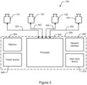
- Method 400 is performed for each camera in system 100 (provided those cameras can view part of the vehicle scene) and will be described for camera 102 only, noting that the operation for cameras 101, 103 and 104 is identical. It will be appreciated that this method can be performed for systems having other numbers of cameras, including a single camera.
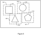
- the identified features are stored as subset regions or coordinates of pixels within the image. This is illustrated schematically in Figure 5 wherein four example reference features 501-504, illustrated as conventional geometric shapes, can be seen.
- the dashed boxes 505-508 around each feature illustrate the pixel regions within the image designated to correspond to those features.
- the pixels can be individually identifiable in two dimensional pixel coordinates of the sensor array. Although the pixel regions are illustrated as being rectilinear, in other embodiments the pixel regions may be defined by other shapes.
- the reference data includes camera orientation data received from an orientation sensor mounted to the camera. This scenario is described in more detail below.
- the orientation data from the sensor may also be compared to second orientation data received from an orientation sensor mounted to the vehicle frame, such as an on-board vehicle sensor.
- method 400 may be performed repeatedly to re-calibrate the camera pose if and when necessary.
- method 400 is performed each time the vehicle is started and system 100 is powered up.
- method 400 allows for automatically determining camera pose without the need for additional system hardware. This ongoing determination significantly improves the performance of monitoring systems such as driver gaze monitoring.
- the use of a three dimensional model is also advantageous in simplifying the installation process of the cameras.
- the cameras can be simply installed at the desired locations without the need to perform an initial determination of camera pose. Rather, the camera pose can be initially determined from method 400.
- Orientation sensors 317-320 may include simple inertial devices such as accelerometers and gyroscopes and other devices such as magnetometers and more advanced inertial measurement units, or combinations thereof. Orientation sensors 317-320 may be capable of measuring orientation in one, two or three dimensions relative to a reference orientation fixed with respect to the vehicle frame of reference.
- a suitable reference system is that described above using the vehicle drive shaft and front wheel axle.
- a reference orientation can be chosen arbitrarily based on the particular application. For example, if two or more cameras were aligned along a common axis, that axis may be preferred as the reference orientation.
- the orientations are preferably expressed in a three dimensional Cartesian coordinate system.
- orientations can be expressed in any arbitrary coordinate system such as a spherical coordinate system wherein an orientation vector is expressed in terms of a radial distance ( r ), a zenith angle ( ⁇ ) in a vertical plane and an azimuthal angle ( ⁇ ) in a horizontal plane.
- the electrical connections 322-325 also provide for transmission of orientation data from orientation sensors 317-320 to processor 302 and memory 304.
- Various types of camera mounts and actuators are able to be used in the present invention, including but not limited to C-type or T-type screw threaded mounts, hydraulic actuator mounts, thermal or magnetic actuator mounts and piezoelectric actuator mounts.
- the cameras are installed in their desired locations within the scene to be monitored and their respective positions and initial orientations are registered in memory 304 through user input device 310.
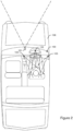
- the cameras are preferably mounted at locations in or around the vehicle such as those in Figures 1 and 2 so as to position the driver and the forward road scene within their respective fields of view.
- Step 1101 may be performed during manufacture of the vehicle or during a subsequent installation of system 100 in vehicle 106.
- the initial position/orientation registration of step 1101 may be performed manually or in a quasi-automated manner utilizing orientation sensors 317-320 and a depth imaging device 340 as described in Australian provisional patent application 2016902544, filed on 29 June 2016 .
- the contents of Australian provisional patent application 2016902544 are incorporated herein by way of cross reference.
- Depth imaging device 340 can include one or more of a scanning or pulsed time of flight camera, LIDAR system, stereoscopic camera arrangement, structured light 3D scanner, image sensor with phase detection or any other imaging system capable of capturing images of a scene in three dimensions.
- Depth imaging device 340 is operatively associated with processor 302 through a dedicated electrical connection to provide control to device 340 and receive raw three dimensional image data or pre-processed depth map data from device 340.
- depth imaging device 340 is connected to central processing unit 300 and processor 302 through network interface 308.
- each unit is electrically connected to central processing unit 300 through respective connections 322-325.
- a reference position and orientation within the scene is defined.
- the reference orientation is a world reference coordinate system defined by the scene geometry.
- the world coordinate system may be the coordinate system described above using the vehicle drive shaft and front wheel axle.
- an arbitrary reference orientation can be chosen by a user through user input device 310 based on the particular application. For example, if two or more cameras were aligned along a common axis, that axis may be a preferred axis for the reference orientation.
- the reference orientation is defined by the scene geometry such that it remains constant over time.
- orientation signals indicative of each camera orientation is received at processor 302 from the respective orientation sensors 317-320 through signals 322-325.
- the orientation signals include a camera orientation in two or three dimensions.
- the orientation sensors may only provide orientation in one dimension and the remaining dimensions may be measured manually or assumed to be unchanged.
- the orientations are defined relative to the reference orientation described above.
- processor 302 receives external input such as velocity or acceleration data of the vehicle, a GPS position of the vehicle, or a current orientation of the vehicle measured by an on-board sensor (e.g. to detect when the car is parked on a slope).
- system 100 may be connected to an onboard vehicle computer system through network interface 308 which provides a feed of vehicle data such as vehicle GPS position, velocity and acceleration.
- the external input data is used to augment the orientation data to aid in the calculation of camera orientations, particularly when the orientation sensor is only capable of measuring orientation in one or two dimensions.
- yaw orientation in the vertical axis
- Measuring a change in position, velocity or acceleration of the camera as the vehicle is in motion can help to determine an overall force vector from which the orientation of the camera in three dimensions can be extrapolated.
- processor 302 calculates a current orientation of each camera and stores the current orientations in memory 304 for subsequent use by monitoring algorithms.
- the orientation signals are monitored for a period of time such as 30 seconds to observe a window of data. This allows processor 302 to determine a steady state orientation and distinguish from small time varying changes in orientation of the cameras.
- the data obtained in step 403 may be incorporated here, particularly when the vehicle is in motion.
- the current camera orientation data is directly updated in the algorithms themselves, which are also stored in memory 304.
- Step 1104 may be performed in real-time, near real-time, or at predetermined time intervals.
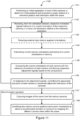
- processor 302 compares the current orientations of each camera with the reference orientations of each camera and derives respective adjustment signals based on the comparisons.
- controller 302 sends the adjustment signals along respective electrical connections 322-325 to control the associated actuators 330-333 of each camera module 312-315 to selectively adjust the orientation of the cameras.
- the adjustment signals represent control signals for controlling the actuator to bring the orientation of the associated camera back into close conformity with the reference orientation or another predefined orientation relative to the reference orientation (to within a margin of error).
- a reference orientation of camera 101 may be expressed as unit orientation vector ⁇ 0,0,1 ⁇ to indicate a direct forward-facing view. After a period of vehicle operation, the actual orientation vector may have shifted to ⁇ 0.2,0.1,1.2 ⁇ .
- the processor 302 performs a vector comparison to determine that a correction of ⁇ -0.2, -0.1, -0.2 ⁇ is required to reorient the camera to its reference position. By referencing an angle-to-voltage/current lookup table stored in memory 304, processor 302 converts this vector correction value to a corresponding electrical control signal to electrically control the corresponding actuator.
- the adjustment signals may include three individual control components or three separate signals.
- the orientation components not able to be adjusted are ignored and assumed to be zero.
- processor 302 may issue an alert to a user to indicate that orientation components unable to be automatically adjusted have drifted outside of a desired range.
- the camera may need to be manually reoriented or method 400 performed to automatically determine the current camera pose.
- a predefined threshold orientation error is defined wherein, if the difference between the current orientation and reference orientation of a camera is less than the threshold orientation error, no adjustment of the camera is performed.
- the threshold orientation error may represent an error limit of the orientation sensor or the minimum resolution of the associated actuator.
- Steps 1102 to 1106 represent the main calibration loop for automatically calibrating the orientation of the cameras within system 1100. Steps 1102 to 1106 may be performed at predetermined regular times during vehicle operation such as at vehicle startup and regular intervals thereafter. Alternatively, steps 1102 to 1106 may be performed in real or near-real time during vehicle operation.
- cameras 101-104 capture streams of images of the scene from the various camera positions/orientations to be processed by processor 302.
- Exemplary processing includes facial feature identification and tracking of a vehicle driver by cameras 102-104 to determine driver drowsiness, attention and eye gaze direction as described, for example, Edwards et al.
- a camera pose for each camera can be determined.
- processor 302 combines the three dimensional position data, orientation data and optionally the external input data for each camera to determine a camera pose for each camera.
- the camera pose includes a six dimensional vector indicating the three dimensional position of the camera sensor array and three dimensional orientation of an optical axis of the camera.
- Processor 302 combines the different camera poses to derive transformation functions for mapping the different camera views within the scene.
- the systems and methods described above provide for efficiently and accurately determining a current pose of cameras in a camera monitoring system.
- the determination is made through comparison to reference information without the need for any additional hardware.
- the system may refer to an accurate three dimensional model of the scene or a previous image captured by the camera at an accurately known camera pose. As described above, this information is sufficient to allow determination of a camera's current pose, even if it has shifted over time.
- the use of a three dimensional model is particularly advantageous as the camera can be easily installed without performing an initial arduous manual calibration procedure.
- the system may determine the camera pose actively using on-board orientation sensors mounted to the cameras.
- the cameras are fitted with actuators for actively adjusting the orientations of cameras. This automatic calibration allows the system to self-align during vehicle operation if the camera orientations are significantly varied by bumps etc. By accurately knowing the pose of the cameras, errors associated with tracking or projecting objects from one camera pose to another are greatly reduced.
- controller or “processor” may refer to any device or portion of a device that processes electronic data, e.g., from registers and/or memory to transform that electronic data into other electronic data that, e.g., may be stored in registers and/or memory.
- a "computer” or a “computing machine” or a “computing platform” may include one or more processors.
- the methodologies described herein are, in one embodiment, performable by one or more processors that accept computer-readable (also called machine-readable) code containing a set of instructions that when executed by one or more of the processors carry out at least one of the methods described herein.
- Any processor capable of executing a set of instructions (sequential or otherwise) that specify actions to be taken are included.
- a typical processing system that includes one or more processors.
- Each processor may include one or more of a CPU, a graphics processing unit, and a programmable DSP unit.
- the processing system further may include a memory subsystem including main RAM and/or a static RAM, and/or ROM.
- a bus subsystem may be included for communicating between the components.
- the processing system further may be a distributed processing system with processors coupled by a network. If the processing system requires a display, such a display may be included, e.g., a liquid crystal display (LCD) or a cathode ray tube (CRT) display. If manual data entry is required, the processing system also includes an input device such as one or more of an alphanumeric input unit such as a keyboard, a pointing control device such as a mouse, and so forth.
- the processing system in some configurations may include a sound output device, and a network interface device.
- the memory subsystem thus includes a computer-readable carrier medium that carries computer-readable code (e.g., software) including a set of instructions to cause performing, when executed by one or more processors, one of more of the methods described herein.
- computer-readable code e.g., software
- the software may reside in the hard disk, or may also reside, completely or at least partially, within the RAM and/or within the processor during execution thereof by the computer system.
- the memory and the processor also constitute computer-readable carrier medium carrying computer-readable code.
- a computer-readable carrier medium may form, or be included in a computer program product.
- the one or more processors operate as a standalone device or may be connected, e.g., networked to other processor(s), in a networked deployment, the one or more processors may operate in the capacity of a server or a user machine in server-user network environment, or as a peer machine in a peer-to-peer or distributed network environment.
- the one or more processors may form a personal computer (PC), a tablet PC, a set-top box (STB), a Personal Digital Assistant (PDA), a cellular telephone, a web appliance, a network router, switch or bridge, or any machine capable of executing a set of instructions (sequential or otherwise) that specify actions to be taken by that machine.
- PC personal computer
- PDA Personal Digital Assistant
- machine shall also be taken to include any collection of machines that individually or jointly execute a set (or multiple sets) of instructions to perform any one or more of the methodologies discussed herein.
- each of the methods described herein is in the form of a computer-readable carrier medium carrying a set of instructions, e.g., a computer program that is for execution on one or more processors, e.g., one or more processors that are part of web server arrangement.
- a computer-readable carrier medium carrying computer readable code including a set of instructions that when executed on one or more processors cause the processor or processors to implement a method.
- aspects of the present invention may take the form of a method, an entirely hardware embodiment, an entirely software embodiment or an embodiment combining software and hardware aspects.
- the present invention may take the form of carrier medium (e.g., a computer program product on a computer-readable storage medium) carrying computer-readable program code embodied in the medium.
- the software may further be transmitted or received over a network via a network interface device.
- the carrier medium is shown in an exemplary embodiment to be a single medium, the term “carrier medium” should be taken to include a single medium or multiple media (e.g., a centralized or distributed database, and/or associated caches and servers) that store the one or more sets of instructions.
- the term “carrier medium” shall also be taken to include any medium that is capable of storing, encoding or carrying a set of instructions for execution by one or more of the processors and that cause the one or more processors to perform any one or more of the methodologies of the present invention.
- a carrier medium may take many forms, including but not limited to, non-volatile media, volatile media, and transmission media.
- Non-volatile media includes, for example, optical, magnetic disks, and magneto-optical disks.
- Volatile media includes dynamic memory, such as main memory.
- Transmission media includes coaxial cables, copper wire and fiber optics, including the wires that comprise a bus subsystem. Transmission media also may also take the form of acoustic or light waves, such as those generated during radio wave and infrared data communications.
- carrier medium shall accordingly be taken to included, but not be limited to, solid-state memories, a computer product embodied in optical and magnetic media; a medium bearing a propagated signal detectable by at least one processor of one or more processors and representing a set of instructions that, when executed, implement a method; and a transmission medium in a network bearing a propagated signal detectable by at least one processor of the one or more processors and representing the set of instructions.
- Coupled when used in the claims, should not be interpreted as being limited to direct connections only.
- the terms “coupled” and “connected,” along with their derivatives, may be used. It should be understood that these terms are not intended as synonyms for each other.
- the scope of the expression a device A coupled to a device B should not be limited to devices or systems wherein an output of device A is directly connected to an input of device B. It means that there exists a path between an output of A and an input of B which may be a path including other devices or means.
- Coupled may mean that two or more elements are either in direct physical, electrical or optical contact, or that two or more elements are not in direct contact with each other but yet still co-operate or interact with each other.
Landscapes
- Engineering & Computer Science (AREA)
- Physics & Mathematics (AREA)
- General Physics & Mathematics (AREA)
- Theoretical Computer Science (AREA)
- Computer Vision & Pattern Recognition (AREA)
- Multimedia (AREA)
- Health & Medical Sciences (AREA)
- General Health & Medical Sciences (AREA)
- Human Computer Interaction (AREA)
- Geometry (AREA)
- Signal Processing (AREA)
- Oral & Maxillofacial Surgery (AREA)
- Ophthalmology & Optometry (AREA)
- Image Analysis (AREA)
- Traffic Control Systems (AREA)
- Length Measuring Devices By Optical Means (AREA)
- Image Processing (AREA)
- Studio Devices (AREA)
Applications Claiming Priority (3)
| Application Number | Priority Date | Filing Date | Title |
|---|---|---|---|
| AU2016902547A AU2016902547A0 (en) | 2016-06-29 | Method for automatic calibration of cameras in a multi-camera system and forward gaze projection | |
| PCT/AU2017/050667 WO2018000037A1 (en) | 2016-06-29 | 2017-06-29 | Systems and methods for identifying pose of cameras in a scene |
| EP17818743.1A EP3479353B1 (de) | 2016-06-29 | 2017-06-29 | Systeme und verfahren zur identifizierung der haltung von kameras in einer szene |
Related Parent Applications (1)
| Application Number | Title | Priority Date | Filing Date |
|---|---|---|---|
| EP17818743.1A Division EP3479353B1 (de) | 2016-06-29 | 2017-06-29 | Systeme und verfahren zur identifizierung der haltung von kameras in einer szene |
Publications (2)
| Publication Number | Publication Date |
|---|---|
| EP4394732A2 true EP4394732A2 (de) | 2024-07-03 |
| EP4394732A3 EP4394732A3 (de) | 2024-10-09 |
Family
ID=60784971
Family Applications (3)
| Application Number | Title | Priority Date | Filing Date |
|---|---|---|---|
| EP17818744.9A Active EP3479356B1 (de) | 2016-06-29 | 2017-06-29 | System und verfahren zur identifizierung einer kamerapose einer nach vorn gerichteten kamera in einem fahrzeug |
| EP17818743.1A Active EP3479353B1 (de) | 2016-06-29 | 2017-06-29 | Systeme und verfahren zur identifizierung der haltung von kameras in einer szene |
| EP24170475.8A Pending EP4394732A3 (de) | 2016-06-29 | 2017-06-29 | Systeme und verfahren zur identifizierung der haltung von kameras in einer szene |
Family Applications Before (2)
| Application Number | Title | Priority Date | Filing Date |
|---|---|---|---|
| EP17818744.9A Active EP3479356B1 (de) | 2016-06-29 | 2017-06-29 | System und verfahren zur identifizierung einer kamerapose einer nach vorn gerichteten kamera in einem fahrzeug |
| EP17818743.1A Active EP3479353B1 (de) | 2016-06-29 | 2017-06-29 | Systeme und verfahren zur identifizierung der haltung von kameras in einer szene |
Country Status (5)
| Country | Link |
|---|---|
| US (2) | US10909721B2 (de) |
| EP (3) | EP3479356B1 (de) |
| JP (1) | JP7161410B2 (de) |
| CN (1) | CN109690623B (de) |
| WO (2) | WO2018000038A1 (de) |
Families Citing this family (77)
| Publication number | Priority date | Publication date | Assignee | Title |
|---|---|---|---|---|
| JP6333871B2 (ja) * | 2016-02-25 | 2018-05-30 | ファナック株式会社 | 入力画像から検出した対象物を表示する画像処理装置 |
| AU2018228284B2 (en) | 2017-03-01 | 2023-08-31 | Synergie Medicale Brg Inc. | System for automatic filling of medication organizers |
| US10929987B2 (en) | 2017-08-16 | 2021-02-23 | Nvidia Corporation | Learning rigidity of dynamic scenes for three-dimensional scene flow estimation |
| US10948299B1 (en) * | 2017-09-28 | 2021-03-16 | Apple Inc. | Relative inertial measurement system with visual correction |
| DE102018203405A1 (de) * | 2018-03-07 | 2019-09-12 | Zf Friedrichshafen Ag | Visuelles Surround-View-System zur Überwachung des Fahrzeuginneren |
| DE112019001414T5 (de) * | 2018-03-19 | 2021-01-21 | Jaguar Land Rover Limited | Steuergerät für ein fahrzeug |
| US10977827B2 (en) * | 2018-03-27 | 2021-04-13 | J. William Mauchly | Multiview estimation of 6D pose |
| EP3803776A4 (de) * | 2018-05-25 | 2022-03-23 | Packsize, LLC | Systeme und verfahren zur mehrkamera-platzierung |
| US10849543B2 (en) | 2018-06-08 | 2020-12-01 | Ford Global Technologies, Llc | Focus-based tagging of sensor data |
| US10991121B2 (en) * | 2018-11-27 | 2021-04-27 | GM Global Technology Operations LLC | Movement tracking of operator-facing cameras |
| US11805390B2 (en) | 2018-12-05 | 2023-10-31 | Here Global B.V. | Method, apparatus, and computer program product for determining sensor orientation |
| EP3896960B1 (de) | 2018-12-11 | 2025-11-26 | Sony Group Corporation | Bildverarbeitungsvorrichtung, bildverarbeitungsverfahren und bildverarbeitungssystem |
| US11677930B2 (en) | 2018-12-20 | 2023-06-13 | Here Global B.V. | Method, apparatus, and system for aligning a vehicle-mounted device |
| US10657396B1 (en) * | 2019-01-30 | 2020-05-19 | StradVision, Inc. | Method and device for estimating passenger statuses in 2 dimension image shot by using 2 dimension camera with fisheye lens |
| US10728461B1 (en) * | 2019-01-31 | 2020-07-28 | StradVision, Inc. | Method for correcting misalignment of camera by selectively using information generated by itself and information generated by other entities and device using the same |
| DE102019201633A1 (de) | 2019-02-08 | 2020-08-13 | Zf Friedrichshafen Ag | Kalibrierung eines Sensors für ein Fahrzeug basierend auf objektseitigen und bildseitigen Identifikationsindizes eines Referenzobjektes |
| DE112020001897T5 (de) * | 2019-04-12 | 2021-12-30 | Nvidia Corporation | Trainieren neuronaler Netze unter Verwendung von Grundwahrheitsdaten, die mit Karteninformationen ergänzt wurden, für autonome Maschinenanwendungen |
| US11639234B2 (en) | 2019-04-24 | 2023-05-02 | The Boeing Company | Method, system and apparatus for aligning a removable sensor on a vehicle |
| CA3076342A1 (en) * | 2019-04-24 | 2020-10-24 | The Boeing Company | Aligning sensors on vehicles using sensor output |
| US12123983B2 (en) | 2019-04-24 | 2024-10-22 | The Boeing Company | Aligning sensors on vehicles using sensor output |
| US11003956B2 (en) * | 2019-05-16 | 2021-05-11 | Naver Corporation | System and method for training a neural network for visual localization based upon learning objects-of-interest dense match regression |
| US11144754B2 (en) * | 2019-08-19 | 2021-10-12 | Nvidia Corporation | Gaze detection using one or more neural networks |
| US11928789B2 (en) | 2019-12-19 | 2024-03-12 | Zf Friedrichshafen Ag | Vehicle vision system |
| WO2021121836A1 (en) * | 2019-12-19 | 2021-06-24 | Sony Semiconductor Solutions Corporation | A camera system for a mobile device, a method for localizing a camera and a method for localizing multiple cameras |
| JP7384043B2 (ja) * | 2020-01-10 | 2023-11-21 | 株式会社デンソー | 検出器の姿勢・位置検出システムおよび検出器の姿勢・位置検出方法 |
| EP3885237B1 (de) * | 2020-03-24 | 2025-06-11 | Aptiv Technologies AG | Fahrzeug, system und verfahren zur bestimmung einer position eine auf dem lenkrad montierte kamera in einem fahrzeug |
| US11568655B2 (en) * | 2020-03-26 | 2023-01-31 | Intel Corporation | Methods and devices for triggering vehicular actions based on passenger actions |
| US11582409B2 (en) * | 2020-06-29 | 2023-02-14 | Snap Inc. | Visual-inertial tracking using rolling shutter cameras |
| KR20220002800A (ko) * | 2020-06-30 | 2022-01-07 | 현대모비스 주식회사 | 운전자 부주의 경고 장치 및 방법 |
| US11232595B1 (en) | 2020-09-08 | 2022-01-25 | Weta Digital Limited | Three-dimensional assembly for motion capture calibration |
| US11282233B1 (en) * | 2020-09-08 | 2022-03-22 | Weta Digital Limited | Motion capture calibration |
| CN120411936A (zh) * | 2020-11-04 | 2025-08-01 | 深圳市卓驭科技有限公司 | 驾驶员数据处理系统及采集驾驶员数据的方法 |
| CN116829902A (zh) | 2020-12-14 | 2023-09-29 | 夏日机器人公司 | 基于感测表面和感测表面运动来感知物体 |
| WO2022140162A1 (en) * | 2020-12-23 | 2022-06-30 | Stoneridge Electronics Ab | Camera mirror system display camera calibration |
| DE112021006203T5 (de) * | 2021-02-12 | 2023-09-14 | Mitsubishi Electric Corporation | Insassenfahrgastzustands-Bestimmungsvorrichtung und Insassenfahrgastzustands-Bestimmungsverfahren |
| US11977150B2 (en) * | 2021-03-05 | 2024-05-07 | Black Sesame Technologies Inc. | Vehicle localization precision enhancement via multi-sensor fusion |
| EP4334884A4 (de) * | 2021-05-05 | 2024-08-21 | Seeing Machines Limited | Systeme und verfahren zur erkennung der verwendung einer mobilen vorrichtung durch einen fahrzeugfahrer |
| US20220363194A1 (en) * | 2021-05-11 | 2022-11-17 | Magna Electronics Inc. | Vehicular display system with a-pillar display |
| US11741661B2 (en) * | 2021-05-14 | 2023-08-29 | Zoox, Inc. | Sensor simulation with unified multi-sensor views |
| US11715257B2 (en) | 2021-05-14 | 2023-08-01 | Zoox, Inc. | Simulation view generation based on simulated sensor operations |
| US11544896B2 (en) | 2021-05-14 | 2023-01-03 | Zoox, Inc. | Spatial and temporal upsampling techniques for simulated sensor data |
| US12111180B2 (en) | 2021-07-01 | 2024-10-08 | Summer Robotics, Inc. | Calibration of sensor position offsets based on rotation and translation vectors for matched trajectories |
| CN113506346B (zh) * | 2021-07-06 | 2023-08-29 | 广东工业大学 | 一种应用于弱纹理大旋转场景下的相机的位姿求解方法 |
| WO2023288067A1 (en) | 2021-07-15 | 2023-01-19 | Summer Robotics, Inc. | Automatic parameter adjustment for scanning event cameras |
| US11704835B2 (en) | 2021-07-29 | 2023-07-18 | Summer Robotics, Inc. | Dynamic calibration of 3D acquisition systems |
| GB2609619A (en) * | 2021-08-05 | 2023-02-15 | Continental Automotive Gmbh | A method for determining deviation in alignment of a camera in a vehicle |
| US11538192B1 (en) * | 2021-08-10 | 2022-12-27 | Fotonation Limited | Method for calibrating a vehicle cabin camera |
| CN117916138A (zh) * | 2021-08-23 | 2024-04-19 | 金泰克斯公司 | 后视组件调整系统 |
| EP4393160A4 (de) | 2021-08-27 | 2025-07-16 | Summer Robotics Inc | Hochauflösendes multisensor-scan- und erfassungssystem |
| WO2023096873A1 (en) | 2021-11-28 | 2023-06-01 | Summer Robotics, Inc. | Association of concurrent tracks across multiple views |
| JP7582214B2 (ja) * | 2022-01-11 | 2024-11-13 | トヨタ自動車株式会社 | 路面標示検出装置及びこれを備える報知システム、並びに路面標示検出方法 |
| JP7134384B1 (ja) * | 2022-01-11 | 2022-09-09 | 三菱電機株式会社 | ずれ量検出装置、ずれ量検出方法及びドライバモニタリングシステム |
| CN114049404B (zh) * | 2022-01-12 | 2022-04-05 | 深圳佑驾创新科技有限公司 | 一种车内相机外参标定方法及装置 |
| US12479364B2 (en) | 2022-02-25 | 2025-11-25 | Gentex Corporation | Vehicle rearview display system with orientation sensing |
| US12511864B2 (en) | 2022-02-27 | 2025-12-30 | Summer Robotics, Inc. | Association of concurrent tracks using graph crossings |
| JP7505660B2 (ja) * | 2022-03-08 | 2024-06-25 | 三菱電機株式会社 | 乗員監視装置、乗員監視方法、及び乗員監視プログラム |
| US11785200B1 (en) | 2022-03-14 | 2023-10-10 | Summer Robotics, Inc. | Stage studio for immersive 3-D video capture |
| KR20230158335A (ko) * | 2022-05-11 | 2023-11-20 | 현대자동차주식회사 | 차량 및 그 제어 방법 |
| US12401905B2 (en) | 2022-07-14 | 2025-08-26 | Summer Robotics, Inc. | Foveated robotic vision system |
| US20240059220A1 (en) * | 2022-08-22 | 2024-02-22 | Seeing Machines Limited | Auto dimming mirror |
| KR20240030098A (ko) * | 2022-08-29 | 2024-03-07 | 현대자동차주식회사 | 차량 및 차량의 제어 방법 |
| US11974055B1 (en) | 2022-10-17 | 2024-04-30 | Summer Robotics, Inc. | Perceiving scene features using event sensors and image sensors |
| EP4365842A1 (de) | 2022-11-02 | 2024-05-08 | Smart Eye AB | Kalibrierung eines kamerakoordinatensystems |
| US12276730B2 (en) | 2022-11-08 | 2025-04-15 | Summer Robotics, Inc. | Virtual fences in air, water, and space |
| US20240249435A1 (en) * | 2023-01-20 | 2024-07-25 | Tusimple, Inc. | System and method for using dynamic objects to estimate camera pose |
| US12340594B2 (en) * | 2023-02-01 | 2025-06-24 | Verizon Patent And Licensing Inc. | Systems and methods for determining road object importance based on forward facing and driver facing video data |
| US12561839B2 (en) * | 2023-02-16 | 2026-02-24 | Ford Global Technologies, Llc | Systems and methods for calibrating image sensors of a vehicle |
| JP2024171980A (ja) * | 2023-05-31 | 2024-12-12 | 株式会社テクノクラフト | 自走式カートの監視システム及びプログラム |
| US12325414B2 (en) * | 2023-06-02 | 2025-06-10 | GM Global Technology Operations LLC | Methods and systems for tracking of attached objects |
| US20240430574A1 (en) * | 2023-06-20 | 2024-12-26 | Rivian Ip Holdings, Llc | Vehicle camera system |
| DE102023122452B3 (de) | 2023-08-22 | 2025-01-23 | Cariad Se | Verfahren zur Ausgabe eines Handlungssignals an einen Insassen in einem Kraftfahrzeug |
| DE102024100306B3 (de) * | 2024-01-08 | 2025-03-20 | Bayerische Motoren Werke Aktiengesellschaft | Vorrichtung und Verfahren zum Kalibrieren einer im Innenraum eines Fahrzeugs angeordneten Innenraumkamera |
| DE102024202949A1 (de) * | 2024-03-28 | 2025-10-02 | Siemens Mobility GmbH | Automatische Überprüfung und Re-Justierung einer statischen Bildaufnahmeeinheit |
| CN120833380A (zh) * | 2024-04-24 | 2025-10-24 | 光宝科技股份有限公司 | 套件装置及标定系统 |
| US20250342609A1 (en) * | 2024-05-06 | 2025-11-06 | DISTANCE TECHNOLOGIES Oy | On-the-fly recalibration of tracking camera |
| US12416804B1 (en) | 2024-05-08 | 2025-09-16 | Summer Robotics, Inc. | Kaleidoscopic laser beam projection system |
| US20250371732A1 (en) * | 2024-05-30 | 2025-12-04 | Nvidia Corporation | Neural network-based identification of poses of cameras |
Citations (1)
| Publication number | Priority date | Publication date | Assignee | Title |
|---|---|---|---|---|
| US7043056B2 (en) | 2000-07-24 | 2006-05-09 | Seeing Machines Pty Ltd | Facial image processing system |
Family Cites Families (61)
| Publication number | Priority date | Publication date | Assignee | Title |
|---|---|---|---|---|
| US8604932B2 (en) | 1992-05-05 | 2013-12-10 | American Vehicular Sciences, LLC | Driver fatigue monitoring system and method |
| JPH10326138A (ja) * | 1997-05-26 | 1998-12-08 | Toshiba Corp | キー入力装置 |
| JP3833786B2 (ja) * | 1997-08-04 | 2006-10-18 | 富士重工業株式会社 | 移動体の3次元自己位置認識装置 |
| US6535114B1 (en) * | 2000-03-22 | 2003-03-18 | Toyota Jidosha Kabushiki Kaisha | Method and apparatus for environment recognition |
| US6354894B1 (en) * | 2000-04-13 | 2002-03-12 | Robert B. Evans | Spear-blade swim fin |
| JP3620443B2 (ja) | 2000-12-05 | 2005-02-16 | 日産自動車株式会社 | 自動車用表示装置 |
| JP3790680B2 (ja) | 2001-05-25 | 2006-06-28 | 株式会社東芝 | 画像処理システム及びこれを用いた運転支援システム |
| DE10159658A1 (de) * | 2001-12-05 | 2003-06-26 | Daimler Chrysler Ag | System zur automatischen Folgeführung eines Kraftfahrzeugs |
| DE10218010A1 (de) * | 2002-04-23 | 2003-11-06 | Bosch Gmbh Robert | Verfahren und Vorrichtung zur Querführungsunterstützung bei Kraftfahrzeugen |
| ATE454849T1 (de) | 2002-10-15 | 2010-01-15 | Volvo Technology Corp | Verfahren für die auswertung der kopf- und augenaktivität einer person |
| US6859144B2 (en) | 2003-02-05 | 2005-02-22 | Delphi Technologies, Inc. | Vehicle situation alert system with eye gaze controlled alert signal generation |
| DE10318500A1 (de) * | 2003-04-24 | 2004-11-25 | Robert Bosch Gmbh | Vorrichtung und Verfahren zur Kalibrierung eines Bildsensors |
| EP1637836A1 (de) * | 2003-05-29 | 2006-03-22 | Olympus Corporation | Einrichtung und verfahren zur unterstützung einer stereokamera,einrichtung und verfahren zur kalibrationsdetektion und stereokamerasystem |
| JP2004354236A (ja) * | 2003-05-29 | 2004-12-16 | Olympus Corp | ステレオカメラ支持装置およびステレオカメラ支持方法ならびにステレオカメラシステム |
| JP4456855B2 (ja) * | 2003-12-08 | 2010-04-28 | 富士重工業株式会社 | 車両の走行制御装置 |
| JP3915776B2 (ja) * | 2003-12-09 | 2007-05-16 | 日産自動車株式会社 | 先行車両検出装置、自車両制御装置及び先行車両検出方法 |
| JP4765301B2 (ja) | 2004-11-25 | 2011-09-07 | 沖電気工業株式会社 | 半導体装置の製造方法 |
| JP4767578B2 (ja) * | 2005-02-14 | 2011-09-07 | 株式会社岩根研究所 | 高精度cv演算装置と、この高精度cv演算装置を備えたcv方式三次元地図生成装置及びcv方式航法装置 |
| JP4926437B2 (ja) * | 2005-09-28 | 2012-05-09 | 富士重工業株式会社 | 車両の運転支援装置 |
| JP4810953B2 (ja) * | 2005-10-07 | 2011-11-09 | 日産自動車株式会社 | 車両用死角映像表示装置 |
| US20090295921A1 (en) * | 2005-10-12 | 2009-12-03 | Pioneer Corporation | Vehicle-mounted photographing device and method of measuring photographable range of vehicle-mounted camera |
| WO2007145566A1 (en) | 2006-06-11 | 2007-12-21 | Volvo Technology Corporation | Method and apparatus for determining and analyzing a location of visual interest |
| US8059887B2 (en) * | 2006-09-25 | 2011-11-15 | Sri International | System and method for providing mobile range sensing |
| KR20090052413A (ko) | 2007-11-21 | 2009-05-26 | 주식회사 현대오토넷 | 운전자 시선 대응 전방 화면 디스플레이 장치 및 방법 |
| JP2009136551A (ja) | 2007-12-07 | 2009-06-25 | Denso Corp | 車両用顔特徴量検出装置及び顔特徴量検出方法 |
| US8392064B2 (en) * | 2008-05-27 | 2013-03-05 | The Board Of Trustees Of The Leland Stanford Junior University | Systems, methods and devices for adaptive steering control of automotive vehicles |
| US8478493B2 (en) * | 2008-09-11 | 2013-07-02 | Deere & Company | High integrity perception program |
| WO2010071928A1 (en) | 2008-12-22 | 2010-07-01 | Seeing Machines Limited | Automatic calibration of a gaze direction algorithm from user behaviour |
| DE102008063328A1 (de) * | 2008-12-30 | 2010-07-01 | Hella Kgaa Hueck & Co. | Verfahren und Vorrichtung zum Ermitteln einer Änderung des Nickwinkels einer Kamera eines Fahrzeugs |
| US8698875B2 (en) * | 2009-02-20 | 2014-04-15 | Google Inc. | Estimation of panoramic camera orientation relative to a vehicle coordinate frame |
| JP2010256878A (ja) * | 2009-03-30 | 2010-11-11 | Equos Research Co Ltd | 情報表示装置 |
| US8766808B2 (en) | 2010-03-09 | 2014-07-01 | Flir Systems, Inc. | Imager with multiple sensor arrays |
| EP2571003B1 (de) * | 2010-05-10 | 2017-07-12 | Toyota Jidosha Kabushiki Kaisha | Risikokalkulator |
| CN103124943A (zh) | 2010-06-10 | 2013-05-29 | 沃尔沃拉斯特瓦格纳公司 | 基于车辆的显示系统和用于操作其的方法 |
| FR2962581B1 (fr) | 2010-07-06 | 2013-07-05 | Imajing | Methode de calibration de l'orientation d'une camera video embarquee |
| US8957948B2 (en) | 2010-08-24 | 2015-02-17 | Siemens Corporation | Geometric calibration of head-worn multi-camera eye tracking system |
| JP5476264B2 (ja) * | 2010-09-22 | 2014-04-23 | 日本放送協会 | カメラトラッキング装置およびそのプログラム |
| JP5892309B2 (ja) | 2011-10-27 | 2016-03-23 | マツダ株式会社 | 車両用視線誘導装置 |
| US8941561B1 (en) | 2012-01-06 | 2015-01-27 | Google Inc. | Image capture |
| US8915738B2 (en) | 2012-01-24 | 2014-12-23 | Toyota Motor Engineering & Manufacturing North America, Inc. | Driver quality assessment for driver education |
| US8880272B1 (en) * | 2012-03-16 | 2014-11-04 | Google Inc. | Approach for estimating the geometry of roads and lanes by using vehicle trajectories |
| US8702250B2 (en) * | 2012-04-02 | 2014-04-22 | GM Global Technology Operations LLC | System and method for adjusting vehicle mirrors automatically based on driver head position |
| US9423870B2 (en) | 2012-05-08 | 2016-08-23 | Google Inc. | Input determination method |
| US9150238B2 (en) * | 2012-06-04 | 2015-10-06 | GM Global Technology Operations LLC | System and method for automatically adjusting a steering tilt position |
| JP5931646B2 (ja) * | 2012-08-20 | 2016-06-08 | Kddi株式会社 | 画像処理装置 |
| US9036865B2 (en) * | 2012-09-12 | 2015-05-19 | International Business Machines Corporation | Location determination for an object using visual data |
| US9405982B2 (en) * | 2013-01-18 | 2016-08-02 | GM Global Technology Operations LLC | Driver gaze detection system |
| KR102118438B1 (ko) | 2013-01-28 | 2020-06-04 | 한국전자통신연구원 | 차량용 헤드업 디스플레이 장치 및 그 방법 |
| US8885925B2 (en) * | 2013-03-12 | 2014-11-11 | Harris Corporation | Method for 3D object identification and pose detection using phase congruency and fractal analysis |
| EP2972478B1 (de) | 2013-03-15 | 2020-12-16 | Uatc, Llc | Verfahren, systeme und vorrichtungen für eine multisensorische stereovision für robotersysteme |
| US9280202B2 (en) | 2013-05-10 | 2016-03-08 | Magna Electronics Inc. | Vehicle vision system |
| US9483703B2 (en) * | 2013-05-14 | 2016-11-01 | University Of Southern California | Online coupled camera pose estimation and dense reconstruction from video |
| US9563951B2 (en) * | 2013-05-21 | 2017-02-07 | Magna Electronics Inc. | Vehicle vision system with targetless camera calibration |
| US9881221B2 (en) | 2013-10-24 | 2018-01-30 | Conduent Business Services, Llc | Method and system for estimating gaze direction of vehicle drivers |
| US9354073B2 (en) | 2013-12-09 | 2016-05-31 | Harman International Industries, Inc. | Eye gaze enabled navigation system |
| JP6264037B2 (ja) * | 2013-12-27 | 2018-01-24 | トヨタ自動車株式会社 | 車両用情報表示装置及び車両用情報表示方法 |
| CN103770733B (zh) * | 2014-01-15 | 2017-01-11 | 中国人民解放军国防科学技术大学 | 一种驾驶员安全驾驶状态检测方法及装置 |
| US9580081B2 (en) | 2014-01-24 | 2017-02-28 | Tobii Ab | Gaze driven interaction for a vehicle |
| GB2528446B (en) * | 2014-07-21 | 2021-08-04 | Tobii Tech Ab | Method and apparatus for detecting and following an eye and/or the gaze direction thereof |
| US9437055B2 (en) * | 2014-08-13 | 2016-09-06 | Bendix Commercial Vehicle Systems Llc | Cabin and trailer body movement determination with camera at the back of the cabin |
| WO2016029939A1 (en) * | 2014-08-27 | 2016-03-03 | Metaio Gmbh | Method and system for determining at least one image feature in at least one image |
-
2017
- 2017-06-29 US US16/311,471 patent/US10909721B2/en active Active
- 2017-06-29 EP EP17818744.9A patent/EP3479356B1/de active Active
- 2017-06-29 JP JP2018563670A patent/JP7161410B2/ja active Active
- 2017-06-29 EP EP17818743.1A patent/EP3479353B1/de active Active
- 2017-06-29 EP EP24170475.8A patent/EP4394732A3/de active Pending
- 2017-06-29 CN CN201780041110.4A patent/CN109690623B/zh active Active
- 2017-06-29 US US16/312,458 patent/US10726576B2/en active Active
- 2017-06-29 WO PCT/AU2017/050668 patent/WO2018000038A1/en not_active Ceased
- 2017-06-29 WO PCT/AU2017/050667 patent/WO2018000037A1/en not_active Ceased
Patent Citations (1)
| Publication number | Priority date | Publication date | Assignee | Title |
|---|---|---|---|---|
| US7043056B2 (en) | 2000-07-24 | 2006-05-09 | Seeing Machines Pty Ltd | Facial image processing system |
Non-Patent Citations (1)
| Title |
|---|
| EDWARDS ET AL.: "Facial Image Processing System", SEEING MACHINES PTY LTD |
Also Published As
| Publication number | Publication date |
|---|---|
| EP3479353A4 (de) | 2020-03-18 |
| EP3479353A1 (de) | 2019-05-08 |
| US10909721B2 (en) | 2021-02-02 |
| JP7161410B2 (ja) | 2022-10-26 |
| EP3479356A4 (de) | 2020-03-25 |
| CN109690623B (zh) | 2023-11-07 |
| EP3479356A1 (de) | 2019-05-08 |
| WO2018000037A1 (en) | 2018-01-04 |
| EP3479353B1 (de) | 2024-05-01 |
| EP4394732A3 (de) | 2024-10-09 |
| JP2019526101A (ja) | 2019-09-12 |
| US20190206084A1 (en) | 2019-07-04 |
| EP3479356B1 (de) | 2025-04-16 |
| US10726576B2 (en) | 2020-07-28 |
| US20190266751A1 (en) | 2019-08-29 |
| WO2018000038A1 (en) | 2018-01-04 |
| CN109690623A (zh) | 2019-04-26 |
Similar Documents
| Publication | Publication Date | Title |
|---|---|---|
| US10909721B2 (en) | Systems and methods for identifying pose of cameras in a scene | |
| US11017558B2 (en) | Camera registration in a multi-camera system | |
| US20210012520A1 (en) | Distance measuring method and device | |
| US11263761B2 (en) | Systems and methods for visual target tracking | |
| CN106529495B (zh) | 一种飞行器的障碍物检测方法和装置 | |
| WO2019140699A1 (en) | Methods and system for multi-target tracking | |
| KR101880185B1 (ko) | 이동체 포즈 추정을 위한 전자 장치 및 그의 이동체 포즈 추정 방법 | |
| US20200357141A1 (en) | Systems and methods for calibrating an optical system of a movable object | |
| EP3734394A1 (de) | Sensorfusion unter verwendung von trägheits- und bildsensoren | |
| CN110049921A (zh) | 用于红外跟踪的方法和系统 | |
| JP2014529727A (ja) | 自動シーン較正 | |
| WO2020061857A1 (en) | Autofocusing camera and systems | |
| EP3486871B1 (de) | Bildsystem und verfahren zum autonomen fahren und/oder zur fahrerassistenz in einem kraftfahrzeug | |
| US11415990B2 (en) | Optical object tracking on focal plane with dynamic focal length | |
| CN120182363A (zh) | 基于神经辐射场的相机对准 | |
| US12561837B2 (en) | Point of interest tracking and estimation | |
| Lee et al. | Wireless stereo vision system development for rotary-wing UAV guidance and control | |
| CN119417910A (zh) | 图像采集装置的外参标定方法、程序产品及设备 | |
| CN121904155A (zh) | 一种基于单目视觉的无人机对尺度不确定地面目标物的定位方法及系统 | |
| CN121330551A (zh) | 一种无人机航拍图像小目标实时检测方法及系统 |
Legal Events
| Date | Code | Title | Description |
|---|---|---|---|
| PUAI | Public reference made under article 153(3) epc to a published international application that has entered the european phase |
Free format text: ORIGINAL CODE: 0009012 |
|
| STAA | Information on the status of an ep patent application or granted ep patent |
Free format text: STATUS: THE APPLICATION HAS BEEN PUBLISHED |
|
| AC | Divisional application: reference to earlier application |
Ref document number: 3479353 Country of ref document: EP Kind code of ref document: P |
|
| AK | Designated contracting states |
Kind code of ref document: A2 Designated state(s): AL AT BE BG CH CY CZ DE DK EE ES FI FR GB GR HR HU IE IS IT LI LT LU LV MC MK MT NL NO PL PT RO RS SE SI SK SM TR |
|
| REG | Reference to a national code |
Ref country code: DE Ref legal event code: R079 Free format text: PREVIOUS MAIN CLASS: G06V0040190000 Ipc: G06T0007730000 |
|
| PUAL | Search report despatched |
Free format text: ORIGINAL CODE: 0009013 |
|
| AK | Designated contracting states |
Kind code of ref document: A3 Designated state(s): AL AT BE BG CH CY CZ DE DK EE ES FI FR GB GR HR HU IE IS IT LI LT LU LV MC MK MT NL NO PL PT RO RS SE SI SK SM TR |
|
| RIC1 | Information provided on ipc code assigned before grant |
Ipc: G06V 20/59 20220101ALI20240830BHEP Ipc: G06T 7/80 20170101ALI20240830BHEP Ipc: G06T 7/73 20170101AFI20240830BHEP |
|
| STAA | Information on the status of an ep patent application or granted ep patent |
Free format text: STATUS: REQUEST FOR EXAMINATION WAS MADE |
|
| 17P | Request for examination filed |
Effective date: 20241125 |
|
| RBV | Designated contracting states (corrected) |
Designated state(s): AL AT BE BG CH CY CZ DE DK EE ES FI FR GB GR HR HU IE IS IT LI LT LU LV MC MK MT NL NO PL PT RO RS SE SI SK SM TR |
|
| GRAP | Despatch of communication of intention to grant a patent |
Free format text: ORIGINAL CODE: EPIDOSNIGR1 |
|
| STAA | Information on the status of an ep patent application or granted ep patent |
Free format text: STATUS: GRANT OF PATENT IS INTENDED |
|
| INTG | Intention to grant announced |
Effective date: 20260122 |
|
| GRAS | Grant fee paid |
Free format text: ORIGINAL CODE: EPIDOSNIGR3 |