EP4394822A2 - Composant céramique électronique multicouche - Google Patents
Composant céramique électronique multicouche Download PDFInfo
- Publication number
- EP4394822A2 EP4394822A2 EP23190551.4A EP23190551A EP4394822A2 EP 4394822 A2 EP4394822 A2 EP 4394822A2 EP 23190551 A EP23190551 A EP 23190551A EP 4394822 A2 EP4394822 A2 EP 4394822A2
- Authority
- EP
- European Patent Office
- Prior art keywords
- electronic component
- central portion
- multilayer electronic
- internal electrodes
- electrode
- Prior art date
- Legal status (The legal status is an assumption and is not a legal conclusion. Google has not performed a legal analysis and makes no representation as to the accuracy of the status listed.)
- Granted
Links
Images


Classifications
-
- H—ELECTRICITY
- H01—ELECTRIC ELEMENTS
- H01G—CAPACITORS; CAPACITORS, RECTIFIERS, DETECTORS, SWITCHING DEVICES, LIGHT-SENSITIVE OR TEMPERATURE-SENSITIVE DEVICES OF THE ELECTROLYTIC TYPE
- H01G4/00—Fixed capacitors; Processes of their manufacture
- H01G4/002—Details
- H01G4/018—Dielectrics
- H01G4/06—Solid dielectrics
- H01G4/08—Inorganic dielectrics
- H01G4/12—Ceramic dielectrics
- H01G4/1209—Ceramic dielectrics characterised by the ceramic dielectric material
- H01G4/1218—Ceramic dielectrics characterised by the ceramic dielectric material based on titanium oxides or titanates
- H01G4/1227—Ceramic dielectrics characterised by the ceramic dielectric material based on titanium oxides or titanates based on alkaline earth titanates
-
- H—ELECTRICITY
- H01—ELECTRIC ELEMENTS
- H01G—CAPACITORS; CAPACITORS, RECTIFIERS, DETECTORS, SWITCHING DEVICES, LIGHT-SENSITIVE OR TEMPERATURE-SENSITIVE DEVICES OF THE ELECTROLYTIC TYPE
- H01G4/00—Fixed capacitors; Processes of their manufacture
- H01G4/30—Stacked capacitors
-
- H—ELECTRICITY
- H01—ELECTRIC ELEMENTS
- H01G—CAPACITORS; CAPACITORS, RECTIFIERS, DETECTORS, SWITCHING DEVICES, LIGHT-SENSITIVE OR TEMPERATURE-SENSITIVE DEVICES OF THE ELECTROLYTIC TYPE
- H01G4/00—Fixed capacitors; Processes of their manufacture
- H01G4/002—Details
- H01G4/005—Electrodes
- H01G4/008—Selection of materials
-
- H—ELECTRICITY
- H01—ELECTRIC ELEMENTS
- H01G—CAPACITORS; CAPACITORS, RECTIFIERS, DETECTORS, SWITCHING DEVICES, LIGHT-SENSITIVE OR TEMPERATURE-SENSITIVE DEVICES OF THE ELECTROLYTIC TYPE
- H01G4/00—Fixed capacitors; Processes of their manufacture
- H01G4/002—Details
- H01G4/005—Electrodes
- H01G4/008—Selection of materials
- H01G4/0085—Fried electrodes
-
- H—ELECTRICITY
- H01—ELECTRIC ELEMENTS
- H01G—CAPACITORS; CAPACITORS, RECTIFIERS, DETECTORS, SWITCHING DEVICES, LIGHT-SENSITIVE OR TEMPERATURE-SENSITIVE DEVICES OF THE ELECTROLYTIC TYPE
- H01G4/00—Fixed capacitors; Processes of their manufacture
- H01G4/002—Details
- H01G4/005—Electrodes
- H01G4/012—Form of non-self-supporting electrodes
-
- H—ELECTRICITY
- H01—ELECTRIC ELEMENTS
- H01G—CAPACITORS; CAPACITORS, RECTIFIERS, DETECTORS, SWITCHING DEVICES, LIGHT-SENSITIVE OR TEMPERATURE-SENSITIVE DEVICES OF THE ELECTROLYTIC TYPE
- H01G4/00—Fixed capacitors; Processes of their manufacture
- H01G4/002—Details
- H01G4/018—Dielectrics
- H01G4/06—Solid dielectrics
- H01G4/08—Inorganic dielectrics
- H01G4/12—Ceramic dielectrics
- H01G4/1209—Ceramic dielectrics characterised by the ceramic dielectric material
-
- H—ELECTRICITY
- H01—ELECTRIC ELEMENTS
- H01G—CAPACITORS; CAPACITORS, RECTIFIERS, DETECTORS, SWITCHING DEVICES, LIGHT-SENSITIVE OR TEMPERATURE-SENSITIVE DEVICES OF THE ELECTROLYTIC TYPE
- H01G4/00—Fixed capacitors; Processes of their manufacture
- H01G4/002—Details
- H01G4/224—Housing; Encapsulation
-
- H—ELECTRICITY
- H01—ELECTRIC ELEMENTS
- H01G—CAPACITORS; CAPACITORS, RECTIFIERS, DETECTORS, SWITCHING DEVICES, LIGHT-SENSITIVE OR TEMPERATURE-SENSITIVE DEVICES OF THE ELECTROLYTIC TYPE
- H01G4/00—Fixed capacitors; Processes of their manufacture
- H01G4/002—Details
- H01G4/228—Terminals
- H01G4/232—Terminals electrically connecting two or more layers of a stacked or rolled capacitor
-
- H—ELECTRICITY
- H01—ELECTRIC ELEMENTS
- H01G—CAPACITORS; CAPACITORS, RECTIFIERS, DETECTORS, SWITCHING DEVICES, LIGHT-SENSITIVE OR TEMPERATURE-SENSITIVE DEVICES OF THE ELECTROLYTIC TYPE
- H01G4/00—Fixed capacitors; Processes of their manufacture
- H01G4/002—Details
- H01G4/228—Terminals
- H01G4/232—Terminals electrically connecting two or more layers of a stacked or rolled capacitor
- H01G4/2325—Terminals electrically connecting two or more layers of a stacked or rolled capacitor characterised by the material of the terminals
-
- H—ELECTRICITY
- H01—ELECTRIC ELEMENTS
- H01G—CAPACITORS; CAPACITORS, RECTIFIERS, DETECTORS, SWITCHING DEVICES, LIGHT-SENSITIVE OR TEMPERATURE-SENSITIVE DEVICES OF THE ELECTROLYTIC TYPE
- H01G4/00—Fixed capacitors; Processes of their manufacture
- H01G4/002—Details
- H01G4/018—Dielectrics
- H01G4/06—Solid dielectrics
- H01G4/08—Inorganic dielectrics
- H01G4/12—Ceramic dielectrics
Definitions
- the present disclosure relates to a multilayer electronic component.
- a multilayer ceramic capacitor (MLCC), a multilayer electronic component may be a chip-type condenser mounted on the printed circuit boards of any of various electronic products, such as an image display device, including a liquid crystal display (LCD), a plasma display panel (PDP), or the like, a computer, a smartphone, or a mobile phone, serving to charge or discharge electricity therein or therefrom.
- an image display device including a liquid crystal display (LCD), a plasma display panel (PDP), or the like, a computer, a smartphone, or a mobile phone, serving to charge or discharge electricity therein or therefrom.
- LCD liquid crystal display
- PDP plasma display panel
- the multilayer ceramic capacitor has a small size, implements high capacitance, and is easily mounted, and may thus be used as a component of various electronic devices.
- leakage current may increase, as an electric field applied at the same voltage increases.
- a central portion of a body may have a higher amount of residual carbon and a higher amount of residual sulfur, compared to an edge of the body, and the carbon and the sulfur may be rapidly oxidized at a high temperature, to destabilize a surface of an internal electrode, thereby reducing connectivity of the internal electrode.
- An aspect of the present disclosure is to provide a multilayer electronic component having improved connectivity of an internal electrode.
- a multilayer electronic component includes a body including a capacitance formation portion in which a plurality of dielectric layers and a plurality of internal electrodes are alternately disposed in a first direction, a first cover portion disposed on one surface of the capacitance formation portion in the first direction and including a dielectric layer, and a second cover portion disposed on the other surface of the capacitance formation portion in the first direction and including a dielectric layer; and an external electrode disposed on the body.
- FIG. 2 is a cross-sectional view schematically illustrating the multilayer electronic component of FIG. 1 , taken along line I-I'.
- FIG. 5 is a graph illustrating a decrease in capacitance according to an Sn amount included in an internal electrode.
- FIG. 7 is an enlarged view of portion P of FIG. 2 .
- Sn is added, rapid shrinkage may occur in length and width directions during a sintering process due to an increase in dielectric sinterability, and accordingly, a thickness of the dielectric layer may increase, resulting in a decrease in capacitance.
- the internal electrodes may be cut to be exposed from the fifth and sixth surfaces 5 and 6 of the body, and, when margin portions 114 and 115 are formed by stacking a single dielectric layer or two or more dielectric layers on both side surfaces of the capacitance formation portion Ac in the third direction (width direction), a portion connecting the first surface and the fifth and sixth surfaces and a portion connecting the second surface and the fifth and sixth surfaces may not have a contracted shape.
- a plurality of dielectric layers 111 forming the body 110 may be in a sintered state, and a boundary between adjacent dielectric layers 111 may be integrated to such an extent that it is difficult to identify the same without using a scanning electron microscope (SEM).
- SEM scanning electron microscope
- the barium titanate-based material may include a BaTiO 3 -based ceramic powder, and examples of the ceramic powder may include BaTiO 3 , or (Ba 1-x Ca x ) TiO 3 (0 ⁇ x ⁇ 1), Ba(Ti 1-y Ca y )O 3 (0 ⁇ y ⁇ 1), (Ba 1-x Ca x ) (Ti 1 - y Zr y )O 3 (0 ⁇ x ⁇ 1, 0 ⁇ y ⁇ 1), Ba(Ti 1-y Zr y )O 3 (0 ⁇ y ⁇ 1), or the like, in which calcium (Ca), zirconium (Zr), or the like is partially dissolved into BaTiO 3 , or the like.
- the ceramic powder may include BaTiO 3 , or (Ba 1-x Ca x ) TiO 3 (0 ⁇ x ⁇ 1), Ba(Ti 1-y Ca y )O 3 (0 ⁇ y ⁇ 1), (Ba 1-x Ca x ) (Ti 1 - y Zr y )O 3 (0 ⁇
- various ceramic additives, organic solvents, binders, dispersants, or the like may be added to powders such as barium titanate (BaTiO 3 ) or the like according to the purpose of the present disclosure.
- the average thickness td of the dielectric layer 111 may mean an average thickness of the dielectric layer 111 disposed between the first and second internal electrodes 121 and 122.
- the average thickness of the dielectric layer 111 may be measured by scanning an image of a cross-section of the body 110 in length and thickness directions (an L-T plane) with a scanning electron microscope (SEM) at a magnification of 10,000. More specifically, an average value thereof may be determined by measuring a thickness of one (1) dielectric layer at thirty (30) equally spaced points in the length direction in the scanned image. The thirty (30) equally spaced points may be designated in the capacitance formation portion Ac. In addition, when such an average value is determined by extensively using measurements of average values to ten (10) dielectric layers, the average thickness of the dielectric layer may be more generalized.
- the body 110 may include a capacitance formation portion Ac in which a plurality of dielectric layers 111 and a plurality of internal electrodes 121 and 122 are alternately disposed in a first direction, a first cover portion C1 disposed on one surface of the capacitance formation portion in the first direction and including a dielectric layer, and a second cover portion C2 disposed on the other surface of the capacitance formation portion in the first direction and including a dielectric layer.
- the first internal electrode 121 may be connected to the first external electrode 131 without being connected to the second external electrode 132, and the second internal electrode 122 may be connected to the second external electrode 132 without being connected to the first external electrode 131. Therefore, the first internal electrode 121 may be formed to be spaced apart from the fourth surface 4 by a predetermined distance, and the second internal electrode 122 may be formed to be spaced apart from the third surface 3 by a predetermined distance.
- first and second internal electrodes 121 and 122 may be electrically separated from each other by the dielectric layer 111 interposed therebetween.
- FIG. 5 is a graph illustrating a decrease in capacitance according to an Sn amount included in an internal electrode.
- FIG. 6 is a graph illustrating a change in thickness of a dielectric layer according to an Sn amount.
- FIGS. 5 and 6 illustrate cases in which all internal electrodes included in a body have the same amount of Sn, and an X-axis is a molar ratio of Sn/(Ni+Sn) measured in a central portion of each of the internal electrodes. It can be seen that, as the molar ratio of Sn/(Ni+Sn) increases, capacitance gradually decreases and a thickness of a dielectric layer gradually increases.
- the central portions of the internal electrodes 121 and 122 may be regions separated by 20 nm or more from an interface with the dielectric layer 111. Referring to FIG. 7 , a molar ratio of Sn/(Ni+Sn) may be measured in a portion ⁇ PP' spaced at least 20 nm from an interface with the dielectric layer.
- an Sn amount in a region adjacent to the interface with the dielectric layer 111 may be twice larger or more than an Sn amount in the central portion.
- a ratio of the number of internal electrodes of which a molar ratio of Sn/(Ni+Sn) measured in a central portion is 0.00066 or less may be 90% or more. Also, among the plurality of internal electrodes 121 and 122, a ratio of the number of internal electrodes of which a molar ratio of Sn/(Ni+Sn) measured in a central portion is 0.00010 or more to 0.00066 or less may be 90% or more. Therefore, a decrease in capacitance and an increase in thickness of a dielectric layer due to addition of Sn may be more effectively suppressed, and connectivity of the internal electrode may be improved.
- a molar ratio of Sn/(Ni+Sn) measured in a central portion of an internal electrode included in K1 and K2 may be 0.00160 or more and 0.0230 or less, and a molar ratio of Sn/(Ni+Sn) measured in a central portion of an internal electrode included in Kc may be 0.00066 or less.
- a ratio of a maximum size of Kc in the first direction relative to a maximum size of the capacitance formation portion Ac in the first direction may be 0.9 or more.
- the average thickness of each of the internal electrodes 121 and 122 may be measured by scanning an image of a cross-section of the body 110 in length and thickness directions (an L-T plane) with a scanning electron microscope (SEM) at a magnification of 10,000. More specifically, an average value thereof may be determined by measuring a thickness of one (1) internal electrode at thirty (30) equally spaced points in the length direction in the scanned image. The thirty (30) equally spaced points may be designated in the capacitance formation portion Ac. In addition, when such an average value is determined by extensively using measurements of average values to ten (10) internal electrodes, the average thickness of each of the internal electrodes may be further generalized.
- a method for controlling an Sn amount of the internal electrode for each position does not need to be particularly limited.
- an Sn amount included in a ceramic green sheet may be adjusted differently for each position, or an Sn amount included in an internal electrode paste may be adjusted differently for each position, or both methods may be applied simultaneously.
- FIG. 8 is a view illustrating a method of manufacturing a multilayer electronic component according to an embodiment of the present disclosure.
- cover portions C1 and C2 may be formed by stacking one or more ceramic green sheets GS to which no paste for internal electrodes is applied in upper and lower portions in the first direction, respectively.
- Ceramic green sheets 11 coated with paste P1 for internal electrodes having a high Sn amount may be disposed below a first cover portion C1 in the first direction and on a second cover portion C2 in the first direction, ceramic green sheets 12 coated with the internal electrode paste P2 for internal electrodes having a low or no Sn amount may be disposed therebetween, and a capacitance formation portion Ac may be stacked, to form a stack body.
- the stack body may be cut to fit a size of a multilayer electronic component, and may be sintered to form a body, and external electrodes may be formed on the body, to prepare the multilayer electronic component.
- An external electrode may be disposed on the third and fourth surfaces 3 and 4 of the body 110.
- External electrodes 131 and 132 may be disposed on the third and fourth surfaces 3 and 4 of the body 110, respectively, and may include first and second external electrodes 131 and 132 respectively connected 121 and 122.
- the external electrodes 131 and 132 may include a band portion extending to one or more of the first, second, fifth, and sixth surfaces of the body 110.
- the multilayer electronic component 100 has two external electrodes 131 and 132
- the number, shapes, and the like of the external electrodes 131 and 132 may depend on shapes of the internal electrodes 121 and 122, and may be changed for other purposes.
- the electrode layers 131a and 132a may have a form in which a sintered electrode and a resin-based electrode are sequentially formed on the body.
- the electrode layers 131a and 132a may be formed by transferring a sheet containing a conductive metal onto a body or by transferring a sheet containing a conductive metal onto the sintered electrode.
- the plating layers 131b and 132b serve to improve mounting characteristics.
- Types of the plating layers 131b and 132b are not particularly limited, and may be plating layers containing at least one of Ni, Sn, Pd, or an alloy thereof, and may be formed as a plurality of layers.
- the plating layers 131b and 132b may be Ni plating layers or Sn plating layers, and an Ni plating layer and an Sn plating layer may be sequentially formed on the electrode layers 131a and 132a. There may be a form in which an Sn plating layer, an Ni plating layer, and an Sn plating layer are sequentially formed.
- the plating layers 131b and 132b may include a plurality of Ni plating layers and/or a plurality of Sn plating layers.
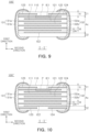
- At least one of a first cover portion C1 or a second cover portion C2 may include dummy electrodes 123 and 124, and a molar ratio of Sn/(Ni+Sn) measured in a central portion of each of the dummy electrodes 123 and 124 may be 0.00160 or more and 0.0230 or less. Since the dummy electrodes 123 and 124 do not affect capacitance formation, reliability of a multilayer electronic component may be further improved without a decrease in capacitance.
- a first cover portion C1 and a second cover portion C2 may include dummy electrodes 123 and 124, respectively, and a molar ratio of Sn/(Ni+Sn) measured in a central portion of each of the dummy electrodes 123 and 124 may be 0.00160 or more and 0.0230 or less.
- both the first cover portion C1 and the second cover portion C2 include the dummy electrodes 123 and 124, reliability may be further improved.
- a multilayer electronic component 100" may include a body 110 including a capacitance formation portion Ac in which a plurality of dielectric layers 111 and a plurality of internal electrodes 121 and 122 are alternately disposed in a first direction, a first cover portion C1 disposed on one surface of the capacitance formation portion in the first direction and including a dielectric layer, and a second cover portion C2 disposed on the other surface of the capacitance formation portion in the first direction and including a dielectric layer; and an external electrode (131 and 132) disposed on the body.
- the first cover portion C1 and the second cover portion C2 may include dummy electrodes 123 and 124, a molar ratio of Sn/(Ni+Sn) measured in a central portion of each of the dummy electrodes 123 and 124 may be 0.00160 or more and 0.0230 or less, a molar ratio of Sn/(Ni+Sn) measured in a central portion of each of the internal electrodes may be 0.00066 or less.
- the present disclosure is not limited thereto, and may include IE1 and IE2, as described above.
- cover portions C1 and C2 were formed by stacking one or more ceramic green sheets GS to which no paste for internal electrodes is applied in upper and lower portions in the first direction, respectively. Ceramic green sheets 11 coated with paste P1 for internal electrodes were disposed below a first cover portion C1 in the first direction and on a second cover portion C2 in the first direction, ceramic green sheets 12 coated with the internal electrode paste P2 for internal electrodes were disposed therebetween, and a capacitance formation portion Ac was stacked, to form a stack body. Thereafter, the stack body was cut to fit a size of a multilayer electronic component, and may be sintered to form a body, and external electrodes were formed on the body, to prepare a sample chip.
- the paste P1 for internal electrodes was adjusted such that a molar ratio of Sn/(Ni+Sn) measured in a central portion of IE1 satisfies Table 1 below
- the paste P2 for internal electrodes was adjusted such that a molar ratio of Sn/(Ni+Sn) measured in a central portion of an internal electrode, except for IE1 and IE2, satisfies 0.00066.
- Capacitance was measured for ten (10) sample chips per each test number, and an average value for each test number was obtained by measuring capacitance using an LCR meter under conditions of an AC voltage of 1 Vrms, and 1 kHz. Capacitance of Test No. 1 was set as a reference value of '100%,' and relative values for the capacitance of Test No. 1 were described for Test Nos. 2 to 9.
- a mean-time-to-failure (MTTF) was measured for the ten (10) sample chips per each test number, a high-temperature load test was conducted under conditions of 165°C and 7.5V, and a time point at which insulation resistance became 10 K ⁇ or less was determined as a failure time, to calcultate an average value thereof.
- a molar ratio of Sn/ (Ni+Sn) of IE1 and IE2 and connectivity of the internal electrode were determined by polishing the sample chips to central portions thereof in the third direction to expose cross-sections in the first and second directions, and measuring in IE1. As illustrated in FIG. 7 , a molar ratio of Sn/(Ni+Sn) was measured in a central portion of IE1 in the length direction, and was measured by performing quantitative analysis of Ni and Sn with STEM-EDS in a 'PP' region, a region spaced at least 20 nm from an interface with a dielectric layer.
- an embodiment presented above is not excluded from being implemented in combination with features of another embodiment. For example, even if a matter described in one detailed embodiment is not described in another embodiment, and it can be understood as a description related to another embodiment, unless there is a description contradicting or contradicting the matter in another embodiment.
- One of various effects of the present disclosure is to adjust Sn amounts of internal electrodes according to positions in which internal electrodes are disposed, to improve reliability of a multilayer electronic component
- One of various effects of the present disclosure is to adjust Sn amounts of internal electrodes according to positions in which internal electrodes are disposed, to improve connectivity of the internal electrode.
- One of various effects of the present disclosure is is to adjust Sn amounts of internal electrodes according to positions in which internal electrodes are disposed, to suppress a decrease in capacitance due to addition of Sn.
Landscapes
- Engineering & Computer Science (AREA)
- Power Engineering (AREA)
- Manufacturing & Machinery (AREA)
- Microelectronics & Electronic Packaging (AREA)
- Chemical & Material Sciences (AREA)
- Ceramic Engineering (AREA)
- Inorganic Chemistry (AREA)
- Materials Engineering (AREA)
- Fixed Capacitors And Capacitor Manufacturing Machines (AREA)
- Ceramic Capacitors (AREA)
Applications Claiming Priority (1)
| Application Number | Priority Date | Filing Date | Title |
|---|---|---|---|
| KR1020220189483A KR20240106561A (ko) | 2022-12-29 | 2022-12-29 | 적층형 전자 부품 |
Publications (3)
| Publication Number | Publication Date |
|---|---|
| EP4394822A2 true EP4394822A2 (fr) | 2024-07-03 |
| EP4394822A3 EP4394822A3 (fr) | 2024-08-21 |
| EP4394822B1 EP4394822B1 (fr) | 2026-01-14 |
Family
ID=87567369
Family Applications (1)
| Application Number | Title | Priority Date | Filing Date |
|---|---|---|---|
| EP23190551.4A Active EP4394822B1 (fr) | 2022-12-29 | 2023-08-09 | Composant électronique céramique multicouche dans lequel les couchettes d'électrodes internes comprennent du nickel (ni) et de l'étain (sn) et une plus grande concentration d'étain (sn) plus proche du couvercle que du centre du corps |
Country Status (5)
| Country | Link |
|---|---|
| US (1) | US12476050B2 (fr) |
| EP (1) | EP4394822B1 (fr) |
| JP (1) | JP2024095953A (fr) |
| KR (1) | KR20240106561A (fr) |
| CN (1) | CN118280729A (fr) |
Families Citing this family (2)
| Publication number | Priority date | Publication date | Assignee | Title |
|---|---|---|---|---|
| KR20240106561A (ko) * | 2022-12-29 | 2024-07-08 | 삼성전기주식회사 | 적층형 전자 부품 |
| JP7723872B1 (ja) | 2024-12-10 | 2025-08-14 | 京セラ株式会社 | 電子部品 |
Citations (1)
| Publication number | Priority date | Publication date | Assignee | Title |
|---|---|---|---|---|
| US20220238280A1 (en) * | 2021-01-27 | 2022-07-28 | Taiyo Yuden Co., Ltd. | Ceramic electronic device and manufacturing method of the same |
Family Cites Families (8)
| Publication number | Priority date | Publication date | Assignee | Title |
|---|---|---|---|---|
| DE112012000798B4 (de) | 2011-02-14 | 2024-05-29 | Murata Manufacturing Co., Ltd. | Verfahren zum Herstellen eines mehrschichtigen Keramikkondensators |
| WO2014024538A1 (fr) * | 2012-08-07 | 2014-02-13 | 株式会社村田製作所 | Condensateur céramique stratifié et procédé de production d'un condensateur céramique stratifié |
| TWI530973B (zh) | 2013-08-02 | 2016-04-21 | Murata Manufacturing Co | Laminated ceramic capacitor and laminated ceramic capacitor manufacturing method |
| KR102105057B1 (ko) * | 2018-08-16 | 2020-04-27 | 삼성전기주식회사 | 적층 세라믹 전자부품 |
| KR102762893B1 (ko) * | 2018-12-12 | 2025-02-07 | 삼성전기주식회사 | 적층 세라믹 전자부품 |
| KR102776268B1 (ko) * | 2020-11-16 | 2025-03-07 | 삼성전기주식회사 | 내부 전극용 도전성 분말, 전자 부품 및 그 제조 방법 |
| JP7459858B2 (ja) * | 2021-12-23 | 2024-04-02 | 株式会社村田製作所 | 積層セラミックコンデンサおよび積層セラミックコンデンサの実装構造 |
| KR20240106561A (ko) * | 2022-12-29 | 2024-07-08 | 삼성전기주식회사 | 적층형 전자 부품 |
-
2022
- 2022-12-29 KR KR1020220189483A patent/KR20240106561A/ko active Pending
-
2023
- 2023-08-08 US US18/231,324 patent/US12476050B2/en active Active
- 2023-08-09 EP EP23190551.4A patent/EP4394822B1/fr active Active
- 2023-08-18 JP JP2023133477A patent/JP2024095953A/ja active Pending
- 2023-11-14 CN CN202311517612.3A patent/CN118280729A/zh active Pending
Patent Citations (1)
| Publication number | Priority date | Publication date | Assignee | Title |
|---|---|---|---|---|
| US20220238280A1 (en) * | 2021-01-27 | 2022-07-28 | Taiyo Yuden Co., Ltd. | Ceramic electronic device and manufacturing method of the same |
Also Published As
| Publication number | Publication date |
|---|---|
| JP2024095953A (ja) | 2024-07-11 |
| EP4394822A3 (fr) | 2024-08-21 |
| US20240222029A1 (en) | 2024-07-04 |
| US12476050B2 (en) | 2025-11-18 |
| EP4394822B1 (fr) | 2026-01-14 |
| CN118280729A (zh) | 2024-07-02 |
| KR20240106561A (ko) | 2024-07-08 |
Similar Documents
| Publication | Publication Date | Title |
|---|---|---|
| JP6632808B2 (ja) | 積層セラミックコンデンサ | |
| US20180061571A1 (en) | Multilayer ceramic electronic component and method of manufacturing the same | |
| US20130235508A1 (en) | Multilayer ceramic electronic component | |
| US20130258546A1 (en) | Multilayer ceramic electronic component and fabrication method thereof | |
| US11657971B2 (en) | Multilayer capacitor | |
| KR20130107799A (ko) | 전자 부품 및 그 제조 방법 | |
| KR102724891B1 (ko) | 적층형 전자 부품 | |
| US20140376150A1 (en) | Multilayer ceramic electronic component | |
| KR20140081568A (ko) | 적층 세라믹 전자 부품 | |
| EP4531065A1 (fr) | Composant électronique multicouche | |
| CN112309718B (zh) | 多层电子组件 | |
| EP4394822A2 (fr) | Composant céramique électronique multicouche | |
| KR20170077542A (ko) | 적층 세라믹 전자부품 및 이의 제조방법 | |
| KR20190121138A (ko) | 적층 세라믹 전자부품의 제조방법 | |
| US20250118490A1 (en) | Multilayer electronic component | |
| EP4418288A2 (fr) | Courbure de l'extrémité des électrodes internes dans la zone d'interface avec les électrodes externes d'un composant électronique multicouche en céramique | |
| US12278057B2 (en) | Ceramic electronic component including barium calcium titanate | |
| KR102881364B1 (ko) | 적층 세라믹 커패시터 | |
| JP2024096025A (ja) | 積層型電子部品 | |
| US20250201480A1 (en) | Multilayer electronic component | |
| US20250218689A1 (en) | Multilayer electronic component | |
| US20250104922A1 (en) | Multilayer electronic component and method for manufacturing the same | |
| US20240387114A1 (en) | Multilayer electronic component | |
| US20250210262A1 (en) | Multilayer electronic component | |
| EP4425513A1 (fr) | Répartition molaire de ba ti et si dans les couches dielectriques pour des composants céramiques multicouches |
Legal Events
| Date | Code | Title | Description |
|---|---|---|---|
| PUAI | Public reference made under article 153(3) epc to a published international application that has entered the european phase |
Free format text: ORIGINAL CODE: 0009012 |
|
| STAA | Information on the status of an ep patent application or granted ep patent |
Free format text: STATUS: THE APPLICATION HAS BEEN PUBLISHED |
|
| AK | Designated contracting states |
Kind code of ref document: A2 Designated state(s): AL AT BE BG CH CY CZ DE DK EE ES FI FR GB GR HR HU IE IS IT LI LT LU LV MC ME MK MT NL NO PL PT RO RS SE SI SK SM TR |
|
| PUAL | Search report despatched |
Free format text: ORIGINAL CODE: 0009013 |
|
| AK | Designated contracting states |
Kind code of ref document: A3 Designated state(s): AL AT BE BG CH CY CZ DE DK EE ES FI FR GB GR HR HU IE IS IT LI LT LU LV MC ME MK MT NL NO PL PT RO RS SE SI SK SM TR |
|
| RIC1 | Information provided on ipc code assigned before grant |
Ipc: H01G 4/008 20060101ALI20240715BHEP Ipc: H01G 4/30 20060101ALI20240715BHEP Ipc: H01G 4/224 20060101ALI20240715BHEP Ipc: H01G 4/232 20060101ALI20240715BHEP Ipc: H01G 4/12 20060101ALI20240715BHEP Ipc: H01G 4/012 20060101ALI20240715BHEP Ipc: H01G 4/00 20060101AFI20240715BHEP |
|
| STAA | Information on the status of an ep patent application or granted ep patent |
Free format text: STATUS: REQUEST FOR EXAMINATION WAS MADE |
|
| 17P | Request for examination filed |
Effective date: 20250212 |
|
| STAA | Information on the status of an ep patent application or granted ep patent |
Free format text: STATUS: EXAMINATION IS IN PROGRESS |
|
| 17Q | First examination report despatched |
Effective date: 20250402 |
|
| GRAP | Despatch of communication of intention to grant a patent |
Free format text: ORIGINAL CODE: EPIDOSNIGR1 |
|
| STAA | Information on the status of an ep patent application or granted ep patent |
Free format text: STATUS: GRANT OF PATENT IS INTENDED |
|
| INTG | Intention to grant announced |
Effective date: 20250813 |
|
| GRAS | Grant fee paid |
Free format text: ORIGINAL CODE: EPIDOSNIGR3 |
|
| GRAA | (expected) grant |
Free format text: ORIGINAL CODE: 0009210 |
|
| STAA | Information on the status of an ep patent application or granted ep patent |
Free format text: STATUS: THE PATENT HAS BEEN GRANTED |
|
| P01 | Opt-out of the competence of the unified patent court (upc) registered |
Free format text: CASE NUMBER: UPC_APP_0013819_4394822/2025 Effective date: 20251119 |
|
| AK | Designated contracting states |
Kind code of ref document: B1 Designated state(s): AL AT BE BG CH CY CZ DE DK EE ES FI FR GB GR HR HU IE IS IT LI LT LU LV MC ME MK MT NL NO PL PT RO RS SE SI SK SM TR |
|
| REG | Reference to a national code |
Ref country code: CH Ref legal event code: F10 Free format text: ST27 STATUS EVENT CODE: U-0-0-F10-F00 (AS PROVIDED BY THE NATIONAL OFFICE) Effective date: 20260114 Ref country code: GB Ref legal event code: FG4D |
|
| REG | Reference to a national code |
Ref country code: DE Ref legal event code: R096 Ref document number: 602023010664 Country of ref document: DE |
|
| REG | Reference to a national code |
Ref country code: IE Ref legal event code: FG4D |