EP4394834A1 - Appareil de technique d'installation domestique - Google Patents
Appareil de technique d'installation domestique Download PDFInfo
- Publication number
- EP4394834A1 EP4394834A1 EP23219296.3A EP23219296A EP4394834A1 EP 4394834 A1 EP4394834 A1 EP 4394834A1 EP 23219296 A EP23219296 A EP 23219296A EP 4394834 A1 EP4394834 A1 EP 4394834A1
- Authority
- EP
- European Patent Office
- Prior art keywords
- light
- rotary knob
- component
- conducting
- domestic installation
- Prior art date
- Legal status (The legal status is an assumption and is not a legal conclusion. Google has not performed a legal analysis and makes no representation as to the accuracy of the status listed.)
- Pending
Links
Images

Classifications
-
- G—PHYSICS
- G05—CONTROLLING; REGULATING
- G05G—CONTROL DEVICES OR SYSTEMS INSOFAR AS CHARACTERISED BY MECHANICAL FEATURES ONLY
- G05G1/00—Controlling members, e.g. knobs or handles; Assemblies or arrangements thereof; Indicating position of controlling members
- G05G1/08—Controlling members for hand actuation by rotary movement, e.g. hand wheels
- G05G1/10—Details, e.g. of discs, knobs, wheels or handles
- G05G1/105—Details, e.g. of discs, knobs, wheels or handles comprising arrangements for illumination
-
- H—ELECTRICITY
- H01—ELECTRIC ELEMENTS
- H01H—ELECTRIC SWITCHES; RELAYS; SELECTORS; EMERGENCY PROTECTIVE DEVICES
- H01H19/00—Switches operated by an operating part which is rotatable about a longitudinal axis thereof and which is acted upon directly by a solid body external to the switch, e.g. by a hand
- H01H19/02—Details
- H01H19/025—Light-emitting indicators
-
- H—ELECTRICITY
- H01—ELECTRIC ELEMENTS
- H01H—ELECTRIC SWITCHES; RELAYS; SELECTORS; EMERGENCY PROTECTIVE DEVICES
- H01H2219/00—Legends
- H01H2219/054—Optical elements
- H01H2219/062—Light conductor
Definitions
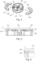
- the invention is in the field of domestic installation technology and relates to a domestic installation technology device, in particular a domestic installation technology device with a mounting insert which has a frame, a lighting insert and a central disk, as well as a rotary knob.
- Devices used in home installation technology include rotary switches, room temperature controllers, volume controls and dimmers. These devices are usually flush-mounted devices that are installed in a wall of a house and are operated by rotating a rotary knob via a shaft protruding from a flush-mounted insert. If this device is a dimmer, for example, then in addition to rotating the rotary knob, an on and off process can be carried out by moving the rotary knob.
- the domestic installation technology device according to the embodiments described here can be manufactured using a simple injection molding process.
- the device described here can simplify the geometries to be produced in such a way that the injection molding tools can also have a simple and cost-effective structure. This reduces production costs and increases process efficiency.
- the domestic installation technology device according to the embodiments described here can dispense with a two-component injection molding process. These process simplifications and reductions brought about by the device described here mean that the manufacture of a domestic installation technology device according to the embodiments described here can also be implemented for smaller quantities.
- the device can be a light dimmer, a room temperature controller, rotary switch, and/or a volume controller.
- the advantages of the device according to the invention come to the fore in particular.
- the better visibility of these everyday objects due to the light-conducting element is accompanied by simplified assembly and thus also reduced costs. This is particularly beneficial to users who benefit from the reduced costs of a light dimmer, room temperature controller, rotary switch, and/or volume controller.
- the light-conducting component and the light-tight component can be designed to be held together when inserted into one another by means of a locking mechanism, a plug connection and/or an anti-twist device in the light-tight component.
- the locking mechanism, the plug connection and the anti-twist device form a reliable and robust way of fastening the light-conducting component in the light-tight component.
- an anti-twist device can be designed by means of protrusions in one component (e.g. the light-conducting component) and depressions in another component (e.g. the light-tight component or in the mounting insert), or vice versa.
- the anti-twist device can be designed in particular in such a way that the components of the rotary knob are prevented from moving relative to one another.
- locking elements, pins, a locking device and/or other elements may be available, which can be attached in particular to the light-tight component, the light-conducting component, the mounting insert and/or other parts of the domestic installation technology device.
- the rotary knob recess can be formed in the form of a slot that extends over part of the circumference of the rotary knob.
- the rotary knob recess/slot can extend in segments over the circumference of the rotary knob.
- the rotary knob recess can consist of two slots that extend almost semicircularly around the rotary knob circumference.
- the rotary knob recess can be produced in a simple manner and is robust, not least due to the simple geometry.
- the light-tight component has an upper part and a lower part.
- the lower part is a part of the light-tight component that faces the mounting insert and/or the central disk.
- the upper part of the light-tight component is typically a part that faces away from the mounting insert and/or the central disk.
- the rotary knob recess can be arranged in the upper part of the light-tight component. Compared to existing devices in domestic installation technology, the position of the light-conducting component is thereby shifted from the lower part (in particular the lower edge) to the upper part (in particular the upper edge) of the rotary knob.
- assembly can be simplified, since in particular assembly of the light-conducting components is possible in almost any orientation of the rotary knob.
Landscapes
- Physics & Mathematics (AREA)
- General Physics & Mathematics (AREA)
- Engineering & Computer Science (AREA)
- Automation & Control Theory (AREA)
- Non-Portable Lighting Devices Or Systems Thereof (AREA)
- Rotary Switch, Piano Key Switch, And Lever Switch (AREA)
Applications Claiming Priority (1)
| Application Number | Priority Date | Filing Date | Title |
|---|---|---|---|
| DE202022107293.0U DE202022107293U1 (de) | 2022-12-29 | 2022-12-29 | Gerät der Hausinstallationstechnik |
Publications (1)
| Publication Number | Publication Date |
|---|---|
| EP4394834A1 true EP4394834A1 (fr) | 2024-07-03 |
Family
ID=86693447
Family Applications (1)
| Application Number | Title | Priority Date | Filing Date |
|---|---|---|---|
| EP23219296.3A Pending EP4394834A1 (fr) | 2022-12-29 | 2023-12-21 | Appareil de technique d'installation domestique |
Country Status (2)
| Country | Link |
|---|---|
| EP (1) | EP4394834A1 (fr) |
| DE (1) | DE202022107293U1 (fr) |
Citations (3)
| Publication number | Priority date | Publication date | Assignee | Title |
|---|---|---|---|---|
| DE112005001091T5 (de) * | 2004-06-30 | 2007-05-16 | Lg Electronics Inc | Wählknopf für eine Waschmaschine und Herstellverfahren für diesen |
| EP2050113B1 (fr) * | 2006-07-26 | 2017-09-06 | BSH Hausgeräte GmbH | Dispositif de reglage tournant |
| EP3748234A1 (fr) * | 2019-06-03 | 2020-12-09 | E.G.O. Elektro-Gerätebau GmbH | Dispositif de commande pour un appareil électrique et procédé de fonctionnement d'un appareil électrique |
-
2022
- 2022-12-29 DE DE202022107293.0U patent/DE202022107293U1/de active Active
-
2023
- 2023-12-21 EP EP23219296.3A patent/EP4394834A1/fr active Pending
Patent Citations (3)
| Publication number | Priority date | Publication date | Assignee | Title |
|---|---|---|---|---|
| DE112005001091T5 (de) * | 2004-06-30 | 2007-05-16 | Lg Electronics Inc | Wählknopf für eine Waschmaschine und Herstellverfahren für diesen |
| EP2050113B1 (fr) * | 2006-07-26 | 2017-09-06 | BSH Hausgeräte GmbH | Dispositif de reglage tournant |
| EP3748234A1 (fr) * | 2019-06-03 | 2020-12-09 | E.G.O. Elektro-Gerätebau GmbH | Dispositif de commande pour un appareil électrique et procédé de fonctionnement d'un appareil électrique |
Also Published As
| Publication number | Publication date |
|---|---|
| DE202022107293U1 (de) | 2023-05-22 |
Similar Documents
| Publication | Publication Date | Title |
|---|---|---|
| DE2810441A1 (de) | Kosmetik-etui | |
| WO2021185902A1 (fr) | Meuble et élément de tiroir pour meuble | |
| EP0700134A2 (fr) | Lampe à faible consommation | |
| CH642479A5 (en) | Push-button switch having a small lamp for visual switch marking | |
| DE20007687U1 (de) | Beleuchtungsvorrichtung | |
| DE202006002583U1 (de) | LED-Leuchte | |
| EP4394834A1 (fr) | Appareil de technique d'installation domestique | |
| DE2322717A1 (de) | Behaelter zur aufnahme und zum verdunsten von fluechtigen substanzen | |
| DE19542913C2 (de) | Beleuchtbare Bedienelementanordnung | |
| EP2381163A2 (fr) | Dispositif d'abat-jour, lampe et ensemble de lampe pour la création d'une telle lampe | |
| DE3935731C1 (en) | Double rosette lining for pipe - made of plastic, esp. polypropylene | |
| EP1248039B1 (fr) | Luminaire avec boîtier étanche à l'eau | |
| DE20019046U1 (de) | Gemusterter Lampenaufbau | |
| EP2466573B1 (fr) | Eclairage | |
| DE1298422B (de) | Signalleuchte | |
| EP4287907B1 (fr) | Élément coulissant avec un dispositif d'éclairage et meuble | |
| EP1013987B1 (fr) | Lampe | |
| DE20312326U1 (de) | Rosetten- oder schildförmiges Beschlagteil mit integrierter Beleuchtungseinrichtung | |
| DE10315771A1 (de) | Leuchte mit geschlossener Lichtabstrahlfläche | |
| DE102023130094A1 (de) | Schubkasten und Verfahren zur Herstellung eines Schubkastens | |
| DE102017130023A1 (de) | Leuchtengehäuse und Leuchte | |
| DE202018106946U1 (de) | Leuchte, insbesondere Wand-, Decken- oder Pendelleuchte | |
| DE2234928A1 (de) | Vorrichtung zur beleuchtung mit glitzereffekten fuer reklame- und/oder dekorationszwecke | |
| DE2203163B2 (de) | Beleuchtungseinrichtung für Zigarrenanzünder, insbesondere für Kraftfahrzeuge | |
| DE20105896U1 (de) | Rahmen mit Montageplatte für elektrische Einrichtungen |
Legal Events
| Date | Code | Title | Description |
|---|---|---|---|
| PUAI | Public reference made under article 153(3) epc to a published international application that has entered the european phase |
Free format text: ORIGINAL CODE: 0009012 |
|
| STAA | Information on the status of an ep patent application or granted ep patent |
Free format text: STATUS: REQUEST FOR EXAMINATION WAS MADE |
|
| 17P | Request for examination filed |
Effective date: 20231221 |
|
| AK | Designated contracting states |
Kind code of ref document: A1 Designated state(s): AL AT BE BG CH CY CZ DE DK EE ES FI FR GB GR HR HU IE IS IT LI LT LU LV MC ME MK MT NL NO PL PT RO RS SE SI SK SM TR |
|
| STAA | Information on the status of an ep patent application or granted ep patent |
Free format text: STATUS: EXAMINATION IS IN PROGRESS |