EP4394957A1 - Brennstoffzelleneinheit - Google Patents
Brennstoffzelleneinheit Download PDFInfo
- Publication number
- EP4394957A1 EP4394957A1 EP22883402.4A EP22883402A EP4394957A1 EP 4394957 A1 EP4394957 A1 EP 4394957A1 EP 22883402 A EP22883402 A EP 22883402A EP 4394957 A1 EP4394957 A1 EP 4394957A1
- Authority
- EP
- European Patent Office
- Prior art keywords
- hydrogen
- air
- fuel cell
- supply
- channel
- Prior art date
- Legal status (The legal status is an assumption and is not a legal conclusion. Google has not performed a legal analysis and makes no representation as to the accuracy of the status listed.)
- Pending
Links
- 239000000446 fuel Substances 0.000 title claims abstract description 172
- 239000001257 hydrogen Substances 0.000 claims abstract description 200
- 229910052739 hydrogen Inorganic materials 0.000 claims abstract description 200
- UFHFLCQGNIYNRP-UHFFFAOYSA-N Hydrogen Chemical compound [H][H] UFHFLCQGNIYNRP-UHFFFAOYSA-N 0.000 claims abstract description 147
- 150000002431 hydrogen Chemical class 0.000 claims abstract description 42
- 239000003054 catalyst Substances 0.000 claims description 62
- 230000004044 response Effects 0.000 claims description 10
- 238000007599 discharging Methods 0.000 claims description 4
- 230000015556 catabolic process Effects 0.000 abstract description 7
- 238000006731 degradation reaction Methods 0.000 abstract description 7
- 238000000034 method Methods 0.000 description 53
- 230000008569 process Effects 0.000 description 48
- 238000010248 power generation Methods 0.000 description 32
- 238000006243 chemical reaction Methods 0.000 description 12
- -1 hydrogen ions Chemical class 0.000 description 10
- 230000008859 change Effects 0.000 description 8
- 239000003792 electrolyte Substances 0.000 description 7
- 238000007254 oxidation reaction Methods 0.000 description 7
- QVGXLLKOCUKJST-UHFFFAOYSA-N atomic oxygen Chemical compound [O] QVGXLLKOCUKJST-UHFFFAOYSA-N 0.000 description 5
- 239000012535 impurity Substances 0.000 description 5
- 230000003647 oxidation Effects 0.000 description 5
- 239000001301 oxygen Substances 0.000 description 5
- 229910052760 oxygen Inorganic materials 0.000 description 5
- 230000004913 activation Effects 0.000 description 4
- 230000009467 reduction Effects 0.000 description 4
- XLYOFNOQVPJJNP-UHFFFAOYSA-N water Substances O XLYOFNOQVPJJNP-UHFFFAOYSA-N 0.000 description 4
- 230000003213 activating effect Effects 0.000 description 3
- 238000004519 manufacturing process Methods 0.000 description 3
- 239000000463 material Substances 0.000 description 3
- 239000007800 oxidant agent Substances 0.000 description 3
- 230000001590 oxidative effect Effects 0.000 description 3
- IJGRMHOSHXDMSA-UHFFFAOYSA-N Atomic nitrogen Chemical compound N#N IJGRMHOSHXDMSA-UHFFFAOYSA-N 0.000 description 2
- 230000007423 decrease Effects 0.000 description 2
- 230000006866 deterioration Effects 0.000 description 2
- 238000010586 diagram Methods 0.000 description 2
- 238000005868 electrolysis reaction Methods 0.000 description 2
- 230000004048 modification Effects 0.000 description 2
- 238000012986 modification Methods 0.000 description 2
- 239000012466 permeate Substances 0.000 description 2
- BASFCYQUMIYNBI-UHFFFAOYSA-N platinum Chemical compound [Pt] BASFCYQUMIYNBI-UHFFFAOYSA-N 0.000 description 2
- 230000000630 rising effect Effects 0.000 description 2
- 238000007789 sealing Methods 0.000 description 2
- OKTJSMMVPCPJKN-UHFFFAOYSA-N Carbon Chemical compound [C] OKTJSMMVPCPJKN-UHFFFAOYSA-N 0.000 description 1
- 230000002159 abnormal effect Effects 0.000 description 1
- 239000006230 acetylene black Substances 0.000 description 1
- 238000000354 decomposition reaction Methods 0.000 description 1
- 230000000694 effects Effects 0.000 description 1
- 125000004435 hydrogen atom Chemical group [H]* 0.000 description 1
- 230000007246 mechanism Effects 0.000 description 1
- 239000012528 membrane Substances 0.000 description 1
- 229910052757 nitrogen Inorganic materials 0.000 description 1
- 229910052697 platinum Inorganic materials 0.000 description 1
- 239000005518 polymer electrolyte Substances 0.000 description 1
- 230000007420 reactivation Effects 0.000 description 1
- 239000007787 solid Substances 0.000 description 1
Images



Classifications
-
- H—ELECTRICITY
- H01—ELECTRIC ELEMENTS
- H01M—PROCESSES OR MEANS, e.g. BATTERIES, FOR THE DIRECT CONVERSION OF CHEMICAL ENERGY INTO ELECTRICAL ENERGY
- H01M8/00—Fuel cells; Manufacture thereof
- H01M8/04—Auxiliary arrangements, e.g. for control of pressure or for circulation of fluids
- H01M8/04298—Processes for controlling fuel cells or fuel cell systems
- H01M8/04694—Processes for controlling fuel cells or fuel cell systems characterised by variables to be controlled
- H01M8/04746—Pressure; Flow
- H01M8/04753—Pressure; Flow of fuel cell reactants
-
- H—ELECTRICITY
- H01—ELECTRIC ELEMENTS
- H01M—PROCESSES OR MEANS, e.g. BATTERIES, FOR THE DIRECT CONVERSION OF CHEMICAL ENERGY INTO ELECTRICAL ENERGY
- H01M8/00—Fuel cells; Manufacture thereof
- H01M8/04—Auxiliary arrangements, e.g. for control of pressure or for circulation of fluids
- H01M8/04082—Arrangements for control of reactant parameters, e.g. pressure or concentration
- H01M8/04089—Arrangements for control of reactant parameters, e.g. pressure or concentration of gaseous reactants
-
- H—ELECTRICITY
- H01—ELECTRIC ELEMENTS
- H01M—PROCESSES OR MEANS, e.g. BATTERIES, FOR THE DIRECT CONVERSION OF CHEMICAL ENERGY INTO ELECTRICAL ENERGY
- H01M8/00—Fuel cells; Manufacture thereof
- H01M8/04—Auxiliary arrangements, e.g. for control of pressure or for circulation of fluids
- H01M8/04082—Arrangements for control of reactant parameters, e.g. pressure or concentration
- H01M8/04201—Reactant storage and supply, e.g. means for feeding, pipes
-
- H—ELECTRICITY
- H01—ELECTRIC ELEMENTS
- H01M—PROCESSES OR MEANS, e.g. BATTERIES, FOR THE DIRECT CONVERSION OF CHEMICAL ENERGY INTO ELECTRICAL ENERGY
- H01M8/00—Fuel cells; Manufacture thereof
- H01M8/04—Auxiliary arrangements, e.g. for control of pressure or for circulation of fluids
- H01M8/04223—Auxiliary arrangements, e.g. for control of pressure or for circulation of fluids during start-up or shut-down; Depolarisation or activation, e.g. purging; Means for short-circuiting defective fuel cells
- H01M8/04238—Depolarisation
-
- H—ELECTRICITY
- H01—ELECTRIC ELEMENTS
- H01M—PROCESSES OR MEANS, e.g. BATTERIES, FOR THE DIRECT CONVERSION OF CHEMICAL ENERGY INTO ELECTRICAL ENERGY
- H01M8/00—Fuel cells; Manufacture thereof
- H01M8/04—Auxiliary arrangements, e.g. for control of pressure or for circulation of fluids
- H01M8/04298—Processes for controlling fuel cells or fuel cell systems
- H01M8/043—Processes for controlling fuel cells or fuel cell systems applied during specific periods
-
- H—ELECTRICITY
- H01—ELECTRIC ELEMENTS
- H01M—PROCESSES OR MEANS, e.g. BATTERIES, FOR THE DIRECT CONVERSION OF CHEMICAL ENERGY INTO ELECTRICAL ENERGY
- H01M8/00—Fuel cells; Manufacture thereof
- H01M8/04—Auxiliary arrangements, e.g. for control of pressure or for circulation of fluids
- H01M8/04298—Processes for controlling fuel cells or fuel cell systems
- H01M8/04313—Processes for controlling fuel cells or fuel cell systems characterised by the detection or assessment of variables; characterised by the detection or assessment of failure or abnormal function
- H01M8/04537—Electric variables
- H01M8/04544—Voltage
- H01M8/04552—Voltage of the individual fuel cell
-
- H—ELECTRICITY
- H01—ELECTRIC ELEMENTS
- H01M—PROCESSES OR MEANS, e.g. BATTERIES, FOR THE DIRECT CONVERSION OF CHEMICAL ENERGY INTO ELECTRICAL ENERGY
- H01M8/00—Fuel cells; Manufacture thereof
- H01M8/04—Auxiliary arrangements, e.g. for control of pressure or for circulation of fluids
- H01M8/04298—Processes for controlling fuel cells or fuel cell systems
- H01M8/04313—Processes for controlling fuel cells or fuel cell systems characterised by the detection or assessment of variables; characterised by the detection or assessment of failure or abnormal function
- H01M8/04537—Electric variables
- H01M8/04544—Voltage
- H01M8/04559—Voltage of fuel cell stacks
-
- H—ELECTRICITY
- H01—ELECTRIC ELEMENTS
- H01M—PROCESSES OR MEANS, e.g. BATTERIES, FOR THE DIRECT CONVERSION OF CHEMICAL ENERGY INTO ELECTRICAL ENERGY
- H01M8/00—Fuel cells; Manufacture thereof
- H01M8/06—Combination of fuel cells with means for production of reactants or for treatment of residues
- H01M8/0662—Treatment of gaseous reactants or gaseous residues, e.g. cleaning
- H01M8/0687—Reactant purification by the use of membranes or filters
-
- H—ELECTRICITY
- H01—ELECTRIC ELEMENTS
- H01M—PROCESSES OR MEANS, e.g. BATTERIES, FOR THE DIRECT CONVERSION OF CHEMICAL ENERGY INTO ELECTRICAL ENERGY
- H01M8/00—Fuel cells; Manufacture thereof
- H01M8/10—Fuel cells with solid electrolytes
- H01M2008/1095—Fuel cells with polymeric electrolytes
-
- H—ELECTRICITY
- H01—ELECTRIC ELEMENTS
- H01M—PROCESSES OR MEANS, e.g. BATTERIES, FOR THE DIRECT CONVERSION OF CHEMICAL ENERGY INTO ELECTRICAL ENERGY
- H01M2250/00—Fuel cells for particular applications; Specific features of fuel cell system
- H01M2250/20—Fuel cells in motive systems, e.g. vehicle, ship, plane
-
- Y—GENERAL TAGGING OF NEW TECHNOLOGICAL DEVELOPMENTS; GENERAL TAGGING OF CROSS-SECTIONAL TECHNOLOGIES SPANNING OVER SEVERAL SECTIONS OF THE IPC; TECHNICAL SUBJECTS COVERED BY FORMER USPC CROSS-REFERENCE ART COLLECTIONS [XRACs] AND DIGESTS
- Y02—TECHNOLOGIES OR APPLICATIONS FOR MITIGATION OR ADAPTATION AGAINST CLIMATE CHANGE
- Y02E—REDUCTION OF GREENHOUSE GAS [GHG] EMISSIONS, RELATED TO ENERGY GENERATION, TRANSMISSION OR DISTRIBUTION
- Y02E60/00—Enabling technologies; Technologies with a potential or indirect contribution to GHG emissions mitigation
- Y02E60/30—Hydrogen technology
- Y02E60/50—Fuel cells
Definitions
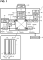
- the hydrogen supply source 41 is a hydrogen inlet and functions as a supply source of hydrogen to be consumed in the fuel cell 1A.
- the hydrogen supply source 41 is connected to a hydrogen tank (not illustrated) to admit hydrogen from the hydrogen tank.
- the hydrogen supply source 41 may be connected to a water electrolysis device instead of the hydrogen tank.
- the air supply source 42 is an air inlet and functions as a supply source of air to be consumed in the fuel cell 1A.
- the air supply source 42 admits air in the atmosphere.
- the air supply source 42 may be connected to an air tank or a water electrolysis device instead. Pressure of hydrogen that is discharged from the hydrogen supply source 41 is set to be higher than pressure of air that is discharged from the air supply source 42.
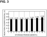
- the changes in the indicators (the maximum stack power and the reaction overpotential) shown in FIGS. 2 and 3 are presumed to be caused by oxidation of the cathode catalyst 12B. From this result, it is understood that the cathode catalyst 12B deteriorates significantly after storage period of at least three months for the fuel cell 1A.
- the fuel cell unit 1 executes a main process (refer to FIG. 5 ) and an electric power generation process (refer to FIG. 8 ), which will be described later, in order to prevent degradation in the performance of the fuel cell 1A that is stored without the external load Ld being not connected to the output terminals 100.
- the CPU 61 controls the fuel cell unit 1 including the controller 6.
- the storage device 62 stores programs for the CPU 61 to execute the main process (refer to FIG. 5 ) and the electric power generation process (refer to FIG. 8 ), which will be described later.
- the storage device 62 stores a flag to be used in the main process and the electric power generation process.
- the flag indicates whether the fuel cell 1A is in a state in which the fuel cell 1A can supply electric power to the external load Ld.
- a state where "a value of the flag is 1 (one)" is referred to as "the flag is ON”.
- a state where "the value of the flag is 0 (zero)" is referred to as "the flag is OFF”.
- the storage device 62 stores a certain period Td as a period specified in advance.
- a value for the certain period Td is not particularly limited, but is specified as, for example, three months that is equal to the storage period of the fuel cell 1A in which the cathode catalyst 12B is significantly degraded.
- the CPU 61 receives digital data output from the AD converter of the voltage measuring unit 5.
- the CPU 61 identifies the voltage between the ends of the voltage dividing resistor of the voltage measuring unit 5 based on the received digital data, thereby identifying a stack voltage of the fuel cell 1A based on the identified voltage.
- the main process starts in response to the CPU 61 executing the program read from the storage device 62 while the fuel cell 1A is in a storage state in which the fuel cell 1A has been stored after manufacturing and the fuel cell 1A has not yet supplied electric power to the external load Ld or in another storage state in which the fuel cell 1A is stored with the external load Ld being not connected to the output terminals 100 after electric power generation is finished.
- the hydrogen supply channel 21 is closed by the hydrogen supply valve 21A
- the hydrogen discharge channel 22 is closed by the hydrogen discharge valve 22A
- the air supply channel 23 is closed by the air supply valve 23A
- the air discharge channel 24 is closed by the air discharge valve 24A.
- the CPU 61 turns the flag ON stored in the storage device 62 to indicate that the fuel cell 1A is in the state in which the fuel cell 1A can supply electric power to the external load Ld (S11).
- the CPU 61 determines whether the certain period Td has elapsed since the CPU 61 turns the flag ON in S11 (S13). If the CPU 61 determines that the certain period Td has not elapsed (S13:NO), the CPU 61 moves the process to S14.
- the CPU 61 determines whether electric power generation has been started by S45 of the electric power generation process (refer to FIG. 8 ) described later (S14). If the CPU 61 determines that the electric power generation has been started (S14:YES), the CPU 61 ends the main process.
- the main process is started in the storage state in which the fuel cell 1A is stored with the external load Ld being not connected to the output terminals 100 after the electric power generation is finished by S49 of the electric power generation process (refer to FIG. 8 ) described later.
- the CPU 61 determines that the electric power generation has not been started (S14:NO)
- the CPU 61 returns the process to S13.
- the CPU 61 waits while repeating the determination in S 14 until the certain period Td elapses since the flag is turned ON.
- the fuel cell 1A is maintained in the state in which the fuel cell 1A can supply electric power to the external load Ld.
- the CPU 61 executes S17 to S27 in order to reduce and activate the oxidized cathode catalyst 12B.
- the CPU 61 controls the air supply value 23A to open the air supply channel 23 once and then close the air supply channel 23 (S17).
- the CPU 61 controls the air discharge valve 24A to open the air discharge channel 24 once and then close the air discharge channel 24 (S19). With such a valve control, the air to the cathode electrodes 12A is interrupted.
- the CPU 61 controls the hydrogen discharge valve 22A to open the hydrogen discharge channel 22 once and then close the hydrogen discharge channel 22 (S21). Next, the CPU 61 controls the hydrogen supply valve 21A to open the hydrogen supply channel 21 (S23). With such a valve control, the hydrogen is supplied to the anode electrodes 11A while the air supply channel 23 and the air discharge channel 24 are closed.
- the hydrogen supply source 41 stores therein hydrogen whose pressure is higher than at least the pressure of the air in the cathode electrodes 12A.
- the anode electrodes 11A are supplied with the hydrogen whose pressure is higher than the pressure of the air in the cathode electrodes 12A.
- the cathode catalyst 12B is activated.
- the anode electrode 11A is supplied with the hydrogen whose pressure is higher than the pressure of the air in the cathode electrode 12A.
- the cathode electrode 12A is filled with the hydrogen that has permeated from the anode electrode 11A as well as the hydrogen in the air. This keeps the cathode catalyst 12B activated and thus the stack voltage lowers.
- the CPU 61 determines that the oxidized cathode catalyst 12B have been sufficiently reduced.
- FIG. 6 shows a relationship between the stack voltage and an elapsed time after the hydrogen is supplied to the anode electrode 11A during S23 to S25.
- FIG. 6 shows a change over time in stack voltage for respective cases where the pressure of the hydrogen supplied to the anode electrode 11A is at 45 KPaG, at 40 KPaG, at 30 KPaG, at 20 KPaG, and at 10 KPaG.
- the stack voltage temporarily rises to about 15 V and then lowers to below the voltage threshold Vh.
- the pressure of the hydrogen is at 45 KPaG, at 40 KPaG, at 30 KPaG, and at 20 KPaG
- the time required for the stack voltage to start rising and the time required for the stack voltage to lower to below the voltage threshold Vh are longer than those when the pressure of the hydrogen is at 10 KPaG.
- the pressure of the hydrogen to be supplied to the anode electrode 11A during S23 to S25 is preferably 20 KPaG or greater.
- the CPU 61 determines that the identified stack voltage is lower than the voltage threshold Vh (S27:YES), the CPU 61 determines that the oxidized cathode catalyst 12B is sufficiently reduced. In response to this, the CPU 61 turns the flag ON to indicate that the fuel cell 1A is in the state in which the fuel cell 1A can supply electric power to the external load Ld (S29).
- the CPU 61 determines whether the certain period Td has elapsed since the CPU 61 turns the flag ON in S11 (S31). If the CPU 61 determines that the certain period Td has not elapsed (S31:NO), the CPU 61 moves the process to S32. The CPU 61 determines whether electric power generation has been started by S45 of the electric power generation process (refer to FIG. 8 ) described later (S32). If the CPU 61 determines that the electric power generation has been started (S32:YES), the CPU 61 ends the main process.
- the main process is started in the storage state in which the fuel cell 1A is stored with the external load Ld being not connected to the output terminals 100 after the electric power generation is finished by S49 of the electric power generation process (refer to FIG. 8 ) described later.
- the CPU 61 determines that the electric power generation has not been started (S32:NO)
- the CPU 61 returns the process to S31.
- the CPU 61 waits while repeating the determination in S32 until the certain period Td elapses since the flag is turned ON.
- the fuel cell 1A is maintained in the state in which the fuel cell 1A can supply electric power to the external load Ld.
- the hydrogen supply channel 21, the hydrogen discharge channel 22, the air supply channel 23, and the air discharge channel 24 are maintained in the closed state.
- the CPU 61 determines that the certain period Td has elapsed since the CPU 61 turns the flag ON (S31:YES), the CPU 61 returns the process to S15.
- the CPU 61 repeats S15 to S29 again.
- the process for reducing the oxidized cathode catalyst 12B is repeatedly executed at the cycle of the certain period Td.
- FIG. 7 shows a change over time in stack power of the fuel cell 1A.
- the horizontal axis of FIG. 7 represents an elapsed time from the start of electric power generation by the fuel cell 1A.
- the stack power of the fuel cell 1A that has not yet supplied electric power to the external load Ld and whose storage period is zero months is about 1600 W at the maximum.
- the stack power of the fuel cell 1A that has been stored for three months without supplying electric power to the external load Ld is about 1250 W at the maximum, which is about 22% less than that in the case where the storage period of the fuel cell 1A is zero months.
- the stack power of the fuel cell 1A that has been stored for three months without supplying electric power to the external load Ld is about 1600 W at the maximum, which is substantially equal to that in the case where the storage period of the fuel cell 1A is zero months.
- the electric power generation process starts at the same timing as the timing at which the main process (refer to FIG. 5 ) starts.
- the electric power generation process is executed in parallel with the main process.
- the CPU 61 determines whether a start instruction for starting electric power supply from the fuel cell 1A to the external load Ld has been received via the input device 63 (S41). If the CPU 61 determines that the start instruction has not been received (S41:NO), the CPU 61 returns the process to S41. The CPU 61 then waits until the start instruction is received.
- the CPU 61 determines whether the flag is ON (S43). If the CPU 61 determines that the flag is OFF (S43:NO), the fuel cell 1A is in the state in which the fuel cell 1A cannot supply electric power to the external load Ld. The CPU 61 thus returns the process to S41. In this case, electric power generation is not performed by the fuel cell 1A, and electric power is not supplied to the external load Ld. If the CPU 61 determines that the flag is ON (S43:YES), the fuel cell 1A is in the state in which the fuel cell 1A can supply electric power to the external load Ld. The CPU 61 thus moves the process to S45.
- the external load Ld is connected to the output terminals 100.
- the CPU 61 executes the following processing to start electric power generation (S45).
- the hydrogen supplied to the anode electrode 11A is decomposed into hydrogen ions and electrons by the anode catalyst 11B.
- the electrons flow toward the cathode electrode 12A through the output terminals 100 and the external load Ld.
- electric power is supplied to the external load Ld.
- the electrons that have come from the anode 11 via the output terminals 100, and oxygen molecules in the air are combined at the cathode catalyst 12B of the cathode 12, thereby generating water.
- the CPU 61 determines whether an end instruction for ending the electric power supply to the external load Ld has been received via the input device 63 (S47). If the CPU 61 determines that the end instruction has not been received (S47:NO), the CPU 61 returns the process to S47. The CPU 61 continues the electric power generation until the CPU 61 determines that the end instruction has been received.
- the CPU 61 determines that the end command has been received via the input device 63 (S47:YES)
- the CPU 61 controls the air supply valve 23A to close the air supply channel 23.
- the CPU 61 controls the air discharge value 24A to close the air discharge channel 24.
- the supply of air to the cathode electrode 12A is interrupted.
- the CPU 61 controls the hydrogen supply valve 21A to close the hydrogen supply channel 21.
- the CPU 61 controls the hydrogen discharge valve 22A to close the hydrogen discharge channel 22.
- the supply of hydrogen to the anode electrode 11A is interrupted.
- the CPU 61 thus ends the electric power generation (S49). Then, the CPU 61 returns the process to S41.
- the anode electrode 11A is supplied with hydrogen that is at a pressure higher than that of air in the cathode electrode 12A by S23.
- the anode electrode 11A is appropriately supplied with the hydrogen and backflow of the hydrogen can be prevented.
- the hydrogen that is at a pressure higher than that of the air in the cathode electrode 12A is supplied to the anode electrode 11A.
- the hydrogen molecules permeate the cathode 12 and can react with the oxidized cathode catalyst 12B.
- the CPU 61 executes the processing for reducing the oxidized cathode catalyst 12B (S15 to S29).
- the cathode catalyst 12B is repeatedly activated at the cycle of the certain period Td. Consequently, in the fuel cell unit 1, degradation in performance of the fuel cell 1A can be prevented although the fuel cell unit 1 is stored for a long time.
- the present invention is not limited to the above-described embodiment, and various modifications are possible.
- the number of cells 10 included in the fuel cell 1A is not limited to that disclosed in the above embodiment.
- the fuel cell 1A may include 1 to 15, 17, or more cells 10.
- the plurality of valves 20A are not limited to the electromagnetic valves, but may be other mechanisms that can open and close the plurality of channels 20.
- the controller 6 of the fuel cell unit 1 is not limited to a personal computer.
- the controller 6 may be a control box that controls the entire fuel cell unit 1.
- the CPU 61 may identify the voltage between the anode electrode 11A and the cathode electrode 12A of any one of the sixteen cells 10 of the fuel cell 1A based on the digital data output by the voltage measuring unit 5. The CPU 61 may wait in S27 until the identified voltage reaches a level lower than 0.1 V that is the voltage lower limit of a single cell 10.
- the certain period Td is not limited to three months, but may be, for example, one, two, or four months.
- the CPU 61 may set a different certain period Td depending on to the elapse of the storage period of the fuel cell 1A. In one example, the CPU 61 may set a longer certain period Td as the storage period of the fuel cell 1A in the state in which the fuel cell 1A has been stored after manufacturing and the fuel cell 1A has not yet supplied electric power to the external load Ld becomes longer.
- the certain period Td used as the determination reference in S13 may be set to be longer than the certain period Td used as the determination reference in S31. In still another example, the certain period Td used as the determination reference in S13 may be set to be shorter than the certain period Td used as the determination reference in S31.
- a filter suitable for impurities to be removed such as a screen filter or a depth filter, may be used as appropriate.
- the CPU 61 may start electric power generation to supply the generated electric power to the external load Ld regardless of whether the start command has been received via the input device 63.
Landscapes
- Life Sciences & Earth Sciences (AREA)
- Engineering & Computer Science (AREA)
- Manufacturing & Machinery (AREA)
- Sustainable Development (AREA)
- Sustainable Energy (AREA)
- Chemical & Material Sciences (AREA)
- Chemical Kinetics & Catalysis (AREA)
- Electrochemistry (AREA)
- General Chemical & Material Sciences (AREA)
- Fuel Cell (AREA)
Applications Claiming Priority (2)
| Application Number | Priority Date | Filing Date | Title |
|---|---|---|---|
| JP2021172124A JP7793929B2 (ja) | 2021-10-21 | 2021-10-21 | 燃料電池ユニット |
| PCT/JP2022/037804 WO2023068098A1 (ja) | 2021-10-21 | 2022-10-11 | 燃料電池ユニット |
Publications (2)
| Publication Number | Publication Date |
|---|---|
| EP4394957A1 true EP4394957A1 (de) | 2024-07-03 |
| EP4394957A4 EP4394957A4 (de) | 2025-04-23 |
Family
ID=86058235
Family Applications (1)
| Application Number | Title | Priority Date | Filing Date |
|---|---|---|---|
| EP22883402.4A Pending EP4394957A4 (de) | 2021-10-21 | 2022-10-11 | Brennstoffzelleneinheit |
Country Status (4)
| Country | Link |
|---|---|
| US (1) | US20240234767A1 (de) |
| EP (1) | EP4394957A4 (de) |
| JP (1) | JP7793929B2 (de) |
| WO (1) | WO2023068098A1 (de) |
Families Citing this family (1)
| Publication number | Priority date | Publication date | Assignee | Title |
|---|---|---|---|---|
| WO2025142047A1 (ja) * | 2023-12-26 | 2025-07-03 | 株式会社クボタ | 作業車両 |
Family Cites Families (10)
| Publication number | Priority date | Publication date | Assignee | Title |
|---|---|---|---|---|
| US6635370B2 (en) | 2001-06-01 | 2003-10-21 | Utc Fuel Cells, Llc | Shut-down procedure for hydrogen-air fuel cell system |
| JP4742501B2 (ja) | 2004-02-17 | 2011-08-10 | 日産自動車株式会社 | 燃料電池システム |
| JP2006134741A (ja) | 2004-11-08 | 2006-05-25 | Nissan Motor Co Ltd | 燃料電池 |
| KR100645690B1 (ko) | 2005-04-12 | 2006-11-14 | 삼성에스디아이 주식회사 | 연료전지 운전중지 방법 및 이를 이용한 연료전지 장치 |
| JP5023374B2 (ja) | 2007-02-05 | 2012-09-12 | トヨタ自動車株式会社 | 燃料電池システム |
| JP5169056B2 (ja) * | 2007-07-31 | 2013-03-27 | 日産自動車株式会社 | 燃料電池システム及びその運転停止方法 |
| JP6792818B2 (ja) * | 2016-09-27 | 2020-12-02 | ブラザー工業株式会社 | 燃料電池システム、燃料電池システムの制御方法、及びコンピュータプログラム |
| JP6614120B2 (ja) | 2016-12-13 | 2019-12-04 | トヨタ自動車株式会社 | 燃料電池セルの触媒活性化方法 |
| JP2019029350A (ja) * | 2017-07-28 | 2019-02-21 | トヨタ自動車株式会社 | 燃料電池システム |
| US20190036132A1 (en) * | 2017-07-28 | 2019-01-31 | Toyota Jidosha Kabushiki Kaisha | Fuel cell system |
-
2021
- 2021-10-21 JP JP2021172124A patent/JP7793929B2/ja active Active
-
2022
- 2022-10-11 EP EP22883402.4A patent/EP4394957A4/de active Pending
- 2022-10-11 WO PCT/JP2022/037804 patent/WO2023068098A1/ja not_active Ceased
-
2024
- 2024-03-25 US US18/615,300 patent/US20240234767A1/en active Pending
Also Published As
| Publication number | Publication date |
|---|---|
| JP2023062256A (ja) | 2023-05-08 |
| EP4394957A4 (de) | 2025-04-23 |
| JP7793929B2 (ja) | 2026-01-06 |
| WO2023068098A1 (ja) | 2023-04-27 |
| US20240234767A1 (en) | 2024-07-11 |
Similar Documents
| Publication | Publication Date | Title |
|---|---|---|
| RU2402841C1 (ru) | Система топливных элементов | |
| USRE38156E1 (en) | Process for operating a PEM fuel cell installation | |
| CN102165637B (zh) | 燃料电池系统和燃料电池系统的异常检测方法 | |
| EP3506407B1 (de) | Brennstoffzellensystem, steuerungsverfahren für brennstoffzellensystem und computerprogramm | |
| JP4495111B2 (ja) | 燃料電池システムにおけるコンタクタ故障検知装置 | |
| KR20070085778A (ko) | 연료 전지 발전 시스템과 그 정지 상태 유지 방법, 정지상태 유지 프로그램 | |
| JP5391226B2 (ja) | 燃料電池システム及びその制御方法 | |
| JPWO2005078844A1 (ja) | 燃料電池システム及び残留燃料ガスの除去方法 | |
| CN106663825B (zh) | 用于启动燃料电池的方法以及燃料电池系统 | |
| CN104733750A (zh) | 燃料电池管理方法 | |
| US7201980B2 (en) | Fuel cell apparatus and method for feeding a fuel for fuel cell | |
| EP4394957A1 (de) | Brennstoffzelleneinheit | |
| CN101467295B (zh) | 燃料电池系统 | |
| EP2475038B1 (de) | Brennstoffzellen-stromerzeugungssystem und betriebsverfahren dafür | |
| JP2007103115A (ja) | 燃料電池システム | |
| JP2012129069A (ja) | 燃料電池システムおよび燃料電池システムの制御方法 | |
| JP2008218051A (ja) | 燃料電池の制御方法 | |
| JP2007059120A (ja) | 燃料電池システム | |
| US20190140292A1 (en) | System and method for controlling performance of fuel cell stack | |
| JP2006156040A (ja) | 燃料電池システム | |
| JP2021009832A (ja) | 燃料電池システム | |
| JP5502955B2 (ja) | 燃料電池システムおよびその制御方法 | |
| JP4559754B2 (ja) | 燃料電池システム | |
| JP4904719B2 (ja) | 燃料電池システム、その制御方法及びそれを搭載した車両 | |
| JP2006140065A (ja) | 燃料電池システム |
Legal Events
| Date | Code | Title | Description |
|---|---|---|---|
| STAA | Information on the status of an ep patent application or granted ep patent |
Free format text: STATUS: THE INTERNATIONAL PUBLICATION HAS BEEN MADE |
|
| PUAI | Public reference made under article 153(3) epc to a published international application that has entered the european phase |
Free format text: ORIGINAL CODE: 0009012 |
|
| STAA | Information on the status of an ep patent application or granted ep patent |
Free format text: STATUS: REQUEST FOR EXAMINATION WAS MADE |
|
| 17P | Request for examination filed |
Effective date: 20240325 |
|
| AK | Designated contracting states |
Kind code of ref document: A1 Designated state(s): AL AT BE BG CH CY CZ DE DK EE ES FI FR GB GR HR HU IE IS IT LI LT LU LV MC ME MK MT NL NO PL PT RO RS SE SI SK SM TR |
|
| P01 | Opt-out of the competence of the unified patent court (upc) registered |
Free format text: CASE NUMBER: APP_44062/2024 Effective date: 20240729 |
|
| DAV | Request for validation of the european patent (deleted) | ||
| DAX | Request for extension of the european patent (deleted) | ||
| A4 | Supplementary search report drawn up and despatched |
Effective date: 20250325 |
|
| RIC1 | Information provided on ipc code assigned before grant |
Ipc: H01M 8/0662 20160101ALN20250319BHEP Ipc: H01M 8/04082 20160101ALN20250319BHEP Ipc: H01M 8/04089 20160101ALN20250319BHEP Ipc: H01M 8/04223 20160101ALI20250319BHEP Ipc: H01M 8/043 20160101ALI20250319BHEP Ipc: H01M 8/10 20160101ALI20250319BHEP Ipc: H01M 8/04746 20160101ALI20250319BHEP Ipc: H01M 8/04537 20160101ALI20250319BHEP Ipc: H01M 8/04303 20160101ALI20250319BHEP Ipc: H01M 8/04228 20160101AFI20250319BHEP |