EP4395077A2 - Mit linsen versehene basisstationsantennen - Google Patents
Mit linsen versehene basisstationsantennen Download PDFInfo
- Publication number
- EP4395077A2 EP4395077A2 EP23202835.7A EP23202835A EP4395077A2 EP 4395077 A2 EP4395077 A2 EP 4395077A2 EP 23202835 A EP23202835 A EP 23202835A EP 4395077 A2 EP4395077 A2 EP 4395077A2
- Authority
- EP
- European Patent Office
- Prior art keywords
- antenna system
- beam antenna
- lens
- radiating elements
- array
- Prior art date
- Legal status (The legal status is an assumption and is not a legal conclusion. Google has not performed a legal analysis and makes no representation as to the accuracy of the status listed.)
- Pending
Links
Images




Classifications
-
- H—ELECTRICITY
- H01—ELECTRIC ELEMENTS
- H01Q—ANTENNAS, i.e. RADIO AERIALS
- H01Q19/00—Combinations of primary active antenna elements and units with secondary devices, e.g. with quasi-optical devices, for giving the antenna a desired directional characteristic
- H01Q19/06—Combinations of primary active antenna elements and units with secondary devices, e.g. with quasi-optical devices, for giving the antenna a desired directional characteristic using refracting or diffracting devices, e.g. lens
- H01Q19/062—Combinations of primary active antenna elements and units with secondary devices, e.g. with quasi-optical devices, for giving the antenna a desired directional characteristic using refracting or diffracting devices, e.g. lens for focusing
-
- H—ELECTRICITY
- H01—ELECTRIC ELEMENTS
- H01Q—ANTENNAS, i.e. RADIO AERIALS
- H01Q1/00—Details of, or arrangements associated with, antennas
- H01Q1/12—Supports; Mounting means
- H01Q1/22—Supports; Mounting means by structural association with other equipment or articles
- H01Q1/24—Supports; Mounting means by structural association with other equipment or articles with receiving set
-
- H—ELECTRICITY
- H01—ELECTRIC ELEMENTS
- H01Q—ANTENNAS, i.e. RADIO AERIALS
- H01Q1/00—Details of, or arrangements associated with, antennas
- H01Q1/12—Supports; Mounting means
- H01Q1/22—Supports; Mounting means by structural association with other equipment or articles
- H01Q1/24—Supports; Mounting means by structural association with other equipment or articles with receiving set
- H01Q1/241—Supports; Mounting means by structural association with other equipment or articles with receiving set used in mobile communications, e.g. GSM
- H01Q1/246—Supports; Mounting means by structural association with other equipment or articles with receiving set used in mobile communications, e.g. GSM specially adapted for base stations
-
- H—ELECTRICITY
- H01—ELECTRIC ELEMENTS
- H01Q—ANTENNAS, i.e. RADIO AERIALS
- H01Q1/00—Details of, or arrangements associated with, antennas
- H01Q1/42—Housings not intimately mechanically associated with radiating elements, e.g. radome
-
- H—ELECTRICITY
- H01—ELECTRIC ELEMENTS
- H01Q—ANTENNAS, i.e. RADIO AERIALS
- H01Q15/00—Devices for reflection, refraction, diffraction or polarisation of waves radiated from an antenna, e.g. quasi-optical devices
- H01Q15/02—Refracting or diffracting devices, e.g. lens, prism
- H01Q15/08—Refracting or diffracting devices, e.g. lens, prism formed of solid dielectric material
-
- H—ELECTRICITY
- H01—ELECTRIC ELEMENTS
- H01Q—ANTENNAS, i.e. RADIO AERIALS
- H01Q19/00—Combinations of primary active antenna elements and units with secondary devices, e.g. with quasi-optical devices, for giving the antenna a desired directional characteristic
- H01Q19/06—Combinations of primary active antenna elements and units with secondary devices, e.g. with quasi-optical devices, for giving the antenna a desired directional characteristic using refracting or diffracting devices, e.g. lens
-
- H—ELECTRICITY
- H01—ELECTRIC ELEMENTS
- H01Q—ANTENNAS, i.e. RADIO AERIALS
- H01Q21/00—Antenna arrays or systems
- H01Q21/06—Arrays of individually energised antenna units similarly polarised and spaced apart
-
- H—ELECTRICITY
- H01—ELECTRIC ELEMENTS
- H01Q—ANTENNAS, i.e. RADIO AERIALS
- H01Q21/00—Antenna arrays or systems
- H01Q21/06—Arrays of individually energised antenna units similarly polarised and spaced apart
- H01Q21/061—Two dimensional planar arrays
- H01Q21/062—Two dimensional planar arrays using dipole aerials
-
- H—ELECTRICITY
- H01—ELECTRIC ELEMENTS
- H01Q—ANTENNAS, i.e. RADIO AERIALS
- H01Q21/00—Antenna arrays or systems
- H01Q21/06—Arrays of individually energised antenna units similarly polarised and spaced apart
- H01Q21/08—Arrays of individually energised antenna units similarly polarised and spaced apart the units being spaced along or adjacent to a rectilinear path
-
- H—ELECTRICITY
- H01—ELECTRIC ELEMENTS
- H01Q—ANTENNAS, i.e. RADIO AERIALS
- H01Q21/00—Antenna arrays or systems
- H01Q21/24—Combinations of antenna units polarised in different directions for transmitting or receiving circularly and elliptically polarised waves or waves linearly polarised in any direction
Definitions
- a multiple beam antenna system in one example of the present invention, includes a first column of radiating elements having a first longitudinal axis and a first azimuth angle, a second column of radiating elements having a second longitudinal axis and a second azimuth angle, and a radio frequency lens.
- the radio frequency lens has a third longitudinal axis.
- the radio frequency lens is disposed such that the longitudinal axes of the first and second columns of radiating elements are aligned with the longitudinal axis of the radio frequency lens, and such that the azimuth angles of the beams produced by the columns of radiating elements are directed at the radio frequency lens.
- One or more columns of radiating elements may be slightly tilted in elevation plane against the axis of radio frequency lens.
- the multiple beam antenna system further includes a radome housing the columns of radiating elements and the radio frequency lens.
- the high band radiating elements include directors to narrow the beamwidth.
- the high band elements are located in two lines in parallel to line of low band elements to narrow the beamwidth produced by the high band elements.
- an antenna system may include at least one column of radiating elements having a first longitudinal axis and an azimuth angle; a radio frequency lens comprising a plurality of dielectric particles and having a second longitudinal axis, the radio frequency lens disposed such that the second longitudinal axis is substantially aligned with the first longitudinal axis and the azimuth angle is directed at the second longitudinal axis; and a radome housing the column of radiating elements and the radio frequency lens.
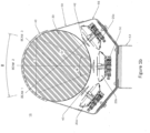
- the radio frequency lens 30 focuses azimuth beams of arrays 20a, 20b, and 20c, changing, for example, their 3dB beam widths from 65° to 23°.
- three linear antenna arrays 20a, 20b, and 20c are shown, but any number and/or shape of arrays 20 may be used.
- the number of beams of a multi-beam base station antenna system 10 is the same as number of ports 70 of arrays 20a, 20b, and 20c.
- each of arrays 20 has 2 ports, one for +45° and another for -45° polarization.
- the lens 30 narrows the HPBW of the antennas arrays 20a, 20b, and 20c while increasing their gain (by 4 - 5 dB for 3-beam antenna shown in Figure 1 ).
- the longitudinal axes of columns of radiating elements of the antenna arrays 20a, 20b, and 20c can be parallel with the longitudinal axis of lens 30.
- axis of antenna arrays 20 can be slightly tilted (2 - 10°) to axis of lens 30 (for example, for better return loss or port-to-port isolation tuning), but axis of an array and axis of lens are still located in the same plane. All antenna arrays 20 share the single lens 30 so each antenna array 20a, 20b, and 20c has their HPBW altered in the same manner.
- lens 30 One difference of lens 30 compared to known Luneberg lenses is its internal structure. As shown in Figure 1b , the dielectric constant ("Dk") of lens 30 is homogenous, in the contrast with known Luneberg lenses which have multiple layers with different Dk. A lens 30 having a homogenous Dk is generally easier and less expensive to manufacture. Also, it can be more compact, having 20 -30% less diameter. In one embodiment, a lens having a Dk of approximately 1.8 and diameter of about 2 wavelengths ⁇ focuses beams and provides azimuth patterns with low sidelobes (less than -17dB), as shown in Figures 10 and 11 .
- Dk dielectric constant
- the array 200 includes a plurality of radiating elements 210, reflector 220, phase shifter /divider 230, and two input connectors 70.
- the phase shifter /divider 230 may be used for beam scanning (beam tilting) in the elevation plane.
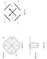
- Each radiating element 210 includes two linear orthogonal polarization (slant +/-45° 311, 312), as shown in more detail in Figure 3c , where 4 equivalent dipoles 313 - 316 are shown forming two orthogonal polarization vectors 311, 312.
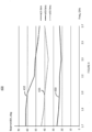
- radiating element 210 and reflector 220 provide a special shape of antenna pattern in the azimuth plane with a close to linear dependence of Azimuth beamwidth with frequency. For example, for a three beam antenna shown in Figure 1 , measured -3dB beamwidth of radiating element 210 is plotted against frequency in Figure 4 (plot 410) and vary from 62° (1.7GHz) to 46° (2.7GHz).
- This simplified analysis illustrates the importance of the frequency dependence of azimuth beam width of linear antennas 20.
- a low band element may have, for example, a HPBW of 65 - 50°,and a high band element may have a HPBW of 45 - 35°, and in the result, the lensed antenna will have stable HPBW of about 23° (and beam width about 40° by -10dB level) across both bands.
- the multi-beam base station antenna system may include one or more secondary lenses. These secondary lenses 43 can be placed between array 20a, 20b, and 20c and lens 30 for further azimuth beamwidth stabilization, as shown in Figure 1B .
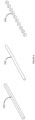
- the secondary lenses may comprise dielectric objects, such as rods 510 and 520 or cubes 530 as shown in Figure 5 . Other shapes may also be used.
- a stable pattern in the very wide frequency band can be provided (e.g. greater than 50%).
- a -10dB beamwidth for a three-beam antenna 420 is 40+/-4° in 1.7 -2.7GHz band (40° is optimal for sector coverage).
- this beamwidth can vary from 28-45°, which is not acceptable for cell sectors because too narrow beams can lead to drop signals in beam-crossing directions, and wide beams (>45°) can lead to undesirable interference between sectors due to overlapping.
- the use of a cylindrical lens significantly reduces grating lobes (and other far sidelobes) in the elevation plane (compare plot 810 is for antenna without lens, and plot 820 for the same antenna with lens).
- plot 810 is for antenna without lens, and plot 820 for the same antenna with lens.
- 5dB grating lobe reduction was observed for 3-beam antenna shown in Figure 1 .
- the 5dB grating lobe reduction is correlated with 5dB gain advantage of lensed antenna Figure 1 against original linear arrays 20.
- the grating lobe's improvement is due to the lens focusing the main beam only and defocusing the far sidelobes. This allows increasing spacing between antenna elements.
- the spacing between array elements depends on grating lobe and is selected by criterion: d max / ⁇ ⁇ 1 / (sin ⁇ 0 +1), where d max is maximum allowed spacing, ⁇ -wavelength and ⁇ 0 is scan angle (see Eli Brookner, Practical Phased Array Antenna Systems, Artech House, 1991, p. 4-5 ).
- compensators 40 and 42 are, in the simplest case, dielectric sheets with certain dielectric constant and thickness.
- the Dk and thickness of the compensator 40 and 42 can be selected for wideband return loss tuning (>15dB at ports 70) and providing desirable port-to-port isolation between all ports 70 (usually need > 30dB).
- second compensator 42 may also compensate reflection from the outer boundary of lens 30, for further improvement of port-to-port isolation.
- Compensators 40 and 42 can have a variety of shapes, such as shapes 710, 720, 730, 740, 750, and 760 shown in Figure 7a , 7b .
- short conductive dipoles may also be used on the surface of compensators 40 and 42 to compensate depolarization of isotropic dielectric cylinder.
- maximum phase delay will occur when vector E is parallel to the dipoles and minimum when perpendicular. So, the process of depolarization can be controlled by placing different orientations of wires on compensators 40 and 42. For example, depolarization of linear polarization can be decreased (axial ratio >20dB), or, if needed, can be converted to circular (axial ratio close to 0dB).
- End caps 64a and 64b, radome 60, and tray 66 provide antenna protection.
- Radome 60 and tray 66 may be made as one extruded plastic piece. Other materials and manufacturing processes may also be used.
- tray 66 is made from metal and acts as an additional reflector to improve antenna back lobes and front-to-back ratio.
- an RF absorber (not shown) can be placed between tray 66 and arrays 20a, 20b, and 20c for additional back lobes' improvement.
- the lens 30 is spaced such that the apertures of the antennas arrays 20a, 20b, and 20c point at a center axis of the lens 30.
- Mounting brackets 53 are used for placing antenna on the tower.
- a radiation pattern without a radio frequency lens 30 is shown (plot 810) which has 5dB higher grating lobe.
- FIG 9 , 10 and 11 radiation patterns of the multi-beam base station antenna system 10 of Figure 1 are shown, measured in azimuth plane.
- co-polar (910) and cross-polar (920) azimuth patterns are shown for central beam.
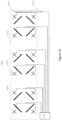
- radio frequency lens 30 has flat top and bottom areas, as it is convenient from mechanical/ assembling point of view (simple flat end cups 64a, 64b can be used). But in some cases, as shown in Figure 12 , a radio frequency lens 1200 with rounded (hemispherical) ends 1210, 1220 may be used. For simplicity, only one linear array 20 is shown in Figure 12 , which can be analogous to linear array 20 presented in Figure 2 . Hemispherical lens ends 1210, 1220 provide additional focusing in elevation plane for edge radiating elements 1230, 1240 resulting in advantage of obtaining of additional gain ⁇ G ⁇ 10log (1 + D/L), [dB], where D is lens diameter. For a three beam antenna as shown in Figure 1 , ⁇ G ⁇ 1dB. Configuration of Figure 12 can be an economically effective way for improving antenna gain, because the additional gain ⁇ G is obtained without increasing lengths of arrays 20 and number of their radiating elements.
- the dual and/or multiband antennas are in demand.
- Such antennas may include, for example antennas providing ports for transmission and reception in the, 698 - 960 MHz + 1.7-2.7GHz bands, or, for example, 1.7-2.7GHz + 3.4-3.8GHz.
- Use of cylindrical lenses gives good opportunity for creating dual-band multi-beam BSA.
- a challenge is providing the same the azimuth beamwidth for all bands and all beams. To get this, azimuth beam width of a low band antenna array (before passing through a radio frequency lens) should be wider compare to a high band antenna array, approximately in proportion of central frequency ratio between the two bands.
Landscapes
- Engineering & Computer Science (AREA)
- Computer Networks & Wireless Communication (AREA)
- Aerials With Secondary Devices (AREA)
- Variable-Direction Aerials And Aerial Arrays (AREA)
Applications Claiming Priority (4)
| Application Number | Priority Date | Filing Date | Title |
|---|---|---|---|
| US201361875491P | 2013-09-09 | 2013-09-09 | |
| US14/244,369 US9780457B2 (en) | 2013-09-09 | 2014-04-03 | Multi-beam antenna with modular luneburg lens and method of lens manufacture |
| PCT/US2014/054814 WO2015035400A2 (en) | 2013-09-09 | 2014-09-09 | Lensed based station antennas |
| EP14767265.3A EP3044831B8 (de) | 2013-09-09 | 2014-09-09 | Linsenbasierte stationsantennen |
Related Parent Applications (2)
| Application Number | Title | Priority Date | Filing Date |
|---|---|---|---|
| EP14767265.3A Division EP3044831B8 (de) | 2013-09-09 | 2014-09-09 | Linsenbasierte stationsantennen |
| EP14767265.3A Division-Into EP3044831B8 (de) | 2013-09-09 | 2014-09-09 | Linsenbasierte stationsantennen |
Publications (2)
| Publication Number | Publication Date |
|---|---|
| EP4395077A2 true EP4395077A2 (de) | 2024-07-03 |
| EP4395077A3 EP4395077A3 (de) | 2025-01-01 |
Family
ID=52625086
Family Applications (2)
| Application Number | Title | Priority Date | Filing Date |
|---|---|---|---|
| EP23202835.7A Pending EP4395077A3 (de) | 2013-09-09 | 2014-09-09 | Mit linsen versehene basisstationsantennen |
| EP14767265.3A Active EP3044831B8 (de) | 2013-09-09 | 2014-09-09 | Linsenbasierte stationsantennen |
Family Applications After (1)
| Application Number | Title | Priority Date | Filing Date |
|---|---|---|---|
| EP14767265.3A Active EP3044831B8 (de) | 2013-09-09 | 2014-09-09 | Linsenbasierte stationsantennen |
Country Status (9)
| Country | Link |
|---|---|
| US (5) | US9780457B2 (de) |
| EP (2) | EP4395077A3 (de) |
| CN (2) | CN105659434B (de) |
| ES (1) | ES2994167T3 (de) |
| HR (1) | HRP20241573T1 (de) |
| HU (1) | HUE069282T2 (de) |
| PL (1) | PL3044831T3 (de) |
| RS (1) | RS66183B1 (de) |
| WO (1) | WO2015035400A2 (de) |
Families Citing this family (103)
| Publication number | Priority date | Publication date | Assignee | Title |
|---|---|---|---|---|
| US9780457B2 (en) | 2013-09-09 | 2017-10-03 | Commscope Technologies Llc | Multi-beam antenna with modular luneburg lens and method of lens manufacture |
| WO2016061825A1 (zh) * | 2014-10-24 | 2016-04-28 | 华为技术有限公司 | 天线系统和处理方法 |
| WO2016081515A1 (en) | 2014-11-18 | 2016-05-26 | Commscope Technologies Llc | Antenna having dielectric sheet loading to control beam width |
| TW201626638A (zh) * | 2015-01-08 | 2016-07-16 | 國立交通大學 | 聚焦天線 |
| US9660323B2 (en) * | 2015-03-27 | 2017-05-23 | T-Mobile Usa, Inc. | Independent adjustable azimuth multi-band antenna fixture |
| US10559982B2 (en) * | 2015-06-10 | 2020-02-11 | Ossia Inc. | Efficient antennas configurations for use in wireless communications and wireless power transmission systems |
| SG10201505215SA (en) * | 2015-06-30 | 2017-01-27 | Matsing Pte Ltd | Dual Polarized Radiator For Lens Antennas |
| US11394124B2 (en) | 2015-08-05 | 2022-07-19 | Matsing, Inc. | Antenna lens switched beam array for tracking satellites |
| US10559886B2 (en) | 2015-08-05 | 2020-02-11 | Matsing, Inc. | Antenna lens array for tracking multiple devices |
| US11431099B2 (en) | 2015-08-05 | 2022-08-30 | Matsing, Inc. | Antenna lens array for azimuth side lobe level reduction |
| US11509057B2 (en) | 2015-08-05 | 2022-11-22 | Matsing, Inc. | RF lens antenna array with reduced grating lobes |
| US11509056B2 (en) | 2015-08-05 | 2022-11-22 | Matsing, Inc. | RF lens antenna array with reduced grating lobes |
| US11909113B2 (en) | 2015-08-05 | 2024-02-20 | Matsing, Inc. | Squinted feeds in lens-based array antennas |
| US11050157B2 (en) | 2015-08-05 | 2021-06-29 | Matsing, Inc. | Antenna lens array for tracking multiple devices |
| US9666943B2 (en) | 2015-08-05 | 2017-05-30 | Matsing Inc. | Lens based antenna for super high capacity wireless communications systems |
| US12586920B2 (en) | 2015-08-05 | 2026-03-24 | Matsing, Inc. | Antenna lens switched beam array for tracking satellites |
| US9728860B2 (en) | 2015-08-05 | 2017-08-08 | Matsing Inc. | Spherical lens array based multi-beam antennae |
| US10418716B2 (en) | 2015-08-27 | 2019-09-17 | Commscope Technologies Llc | Lensed antennas for use in cellular and other communications systems |
| EP3382800B1 (de) * | 2015-11-24 | 2021-08-04 | Murata Manufacturing Co., Ltd. | Antennenvorrichtung mit lüneburg-linse |
| EP3401999B1 (de) * | 2016-01-07 | 2020-10-07 | Murata Manufacturing Co., Ltd. | Antennenvorrichtung mit lüneburg-linse |
| KR102482836B1 (ko) | 2016-01-07 | 2022-12-29 | 삼성전자주식회사 | 안테나 장치를 구비하는 전자 장치 |
| WO2017127378A1 (en) * | 2016-01-19 | 2017-07-27 | Commscope Technologies Llc | Multi-beam antennas having lenses formed of a lightweight dielectric material |
| US11283186B2 (en) | 2016-03-25 | 2022-03-22 | Commscope Technologies Llc | Antennas having lenses formed of lightweight dielectric materials and related dielectric materials |
| US11431100B2 (en) * | 2016-03-25 | 2022-08-30 | Commscope Technologies Llc | Antennas having lenses formed of lightweight dielectric materials and related dielectric materials |
| WO2017173208A1 (en) * | 2016-03-31 | 2017-10-05 | Commscope Technologies Llc | Lensed antennas for use in wireless communications systems |
| CN105846043A (zh) * | 2016-04-05 | 2016-08-10 | 国鹰航空科技有限公司 | 用于无人机平台的平面馈源介质透镜天线 |
| CN107275808B (zh) | 2016-04-08 | 2021-05-25 | 康普技术有限责任公司 | 超宽频带辐射器和相关的天线阵列 |
| EP3242358B1 (de) | 2016-05-06 | 2020-06-17 | Amphenol Antenna Solutions, Inc. | Mehrstrahlantenne für 5g-drahtloskommunikation mit hoher verstärkung |
| CN107623174B (zh) | 2016-07-14 | 2021-02-12 | 华为技术有限公司 | 介质透镜以及劈裂天线 |
| US10165398B2 (en) | 2016-08-23 | 2018-12-25 | General Electric Company | Geofencing for wireless communications |
| CN109643839B (zh) | 2016-09-07 | 2021-02-19 | 康普技术有限责任公司 | 适合用于蜂窝和其它通信系统的多频带多波束透镜式天线 |
| US10069211B2 (en) * | 2016-09-16 | 2018-09-04 | The United States Of America As Represented By The Secretary Of The Navy | Broadband circularly polarized patch antenna and method |
| WO2018089340A1 (en) | 2016-11-10 | 2018-05-17 | Commscope Technologies Llc | Lensed base station antennas having azimuth beam width stabilization |
| US20180159246A1 (en) * | 2016-12-05 | 2018-06-07 | GM Global Technology Operations LLC | Modular architecture of the mimo radar |
| US10381716B2 (en) | 2017-01-13 | 2019-08-13 | Matsing, Inc. | Multi-beam MIMO antenna systems and methods |
| CN114171934B (zh) * | 2017-01-24 | 2025-10-17 | 户外无线网络有限公司 | 基站天线单元及用于安装基站天线单元的方法 |
| US10356632B2 (en) * | 2017-01-27 | 2019-07-16 | Cohere Technologies, Inc. | Variable beamwidth multiband antenna |
| CN110402499B (zh) | 2017-02-03 | 2023-11-03 | 康普技术有限责任公司 | 适于mimo操作的小小区天线 |
| KR102570123B1 (ko) * | 2017-02-21 | 2023-08-23 | 삼성전자 주식회사 | 위상 보상 렌즈 안테나 장치 |
| US11283189B2 (en) | 2017-05-02 | 2022-03-22 | Rogers Corporation | Connected dielectric resonator antenna array and method of making the same |
| US10431877B2 (en) | 2017-05-12 | 2019-10-01 | Commscope Technologies Llc | Base station antennas having parasitic coupling units |
| KR102312067B1 (ko) * | 2017-06-07 | 2021-10-13 | 로저스코포레이션 | 유전체 공진기 안테나 시스템 |
| US10985454B2 (en) | 2017-06-15 | 2021-04-20 | Commscope Technologies Llc | Base station antennas having bottom end caps with angled connector ports |
| KR101926986B1 (ko) * | 2017-06-30 | 2018-12-07 | 한국과학기술원 | 렌즈를 포함하는 안테나 장치 및 렌즈 안테나를 이용한 통신 방법 |
| US10530440B2 (en) * | 2017-07-18 | 2020-01-07 | Commscope Technologies Llc | Small cell antennas suitable for MIMO operation |
| CN107946774B (zh) * | 2017-08-18 | 2018-11-13 | 西安肖氏天线科技有限公司 | 基于人工介质圆柱透镜全向多波束天线 |
| CN107959122B (zh) * | 2017-08-18 | 2019-03-12 | 西安肖氏天线科技有限公司 | 一种超轻人工介质多层圆柱透镜 |
| US11527835B2 (en) | 2017-09-15 | 2022-12-13 | Commscope Technologies Llc | Methods of preparing a composite dielectric material |
| US10587034B2 (en) | 2017-09-29 | 2020-03-10 | Commscope Technologies Llc | Base station antennas with lenses for reducing upwardly-directed radiation |
| US11133586B2 (en) * | 2017-10-31 | 2021-09-28 | Communication Components Antenna Inc. | Antenna array with ABFN circuitry |
| US11616302B2 (en) | 2018-01-15 | 2023-03-28 | Rogers Corporation | Dielectric resonator antenna having first and second dielectric portions |
| US11336023B2 (en) | 2018-01-19 | 2022-05-17 | Matsing, Inc. | 360 degree communications lenses and systems |
| CN111684653B (zh) | 2018-02-06 | 2022-04-22 | 康普技术有限责任公司 | 产生具有全向方位角图案的天线波束的带透镜的基站天线 |
| CN108539430B (zh) * | 2018-02-09 | 2020-10-13 | 曲阜师范大学 | 具有单通带和双侧吸收频带的超材料 |
| DE102018120612A1 (de) * | 2018-02-23 | 2019-08-29 | Kathrein Se | Multibandantennenanordnung für Mobilfunkanwendungen |
| US10700420B2 (en) | 2018-03-05 | 2020-06-30 | Commscope Technologies Llc | Compact multiband feed for small cell base station antennas |
| CN111989824B (zh) * | 2018-07-05 | 2023-04-18 | 康普技术有限责任公司 | 具有天线罩影响消除特征的多带基站天线 |
| WO2020028363A1 (en) * | 2018-07-31 | 2020-02-06 | Quintel Cayman Limited | Split diamond antenna element for controlling azimuth pattern in different array configurations |
| WO2020040996A1 (en) * | 2018-08-24 | 2020-02-27 | Commscope Technologies Llc | Sidelobe suppression in multi-beam base station antennas |
| WO2020041467A1 (en) * | 2018-08-24 | 2020-02-27 | Commscope Technologies Llc | Lensed base station antennas having staggered vertical arrays for azimuth beam width stabilization |
| US11552390B2 (en) | 2018-09-11 | 2023-01-10 | Rogers Corporation | Dielectric resonator antenna system |
| WO2020076814A1 (en) * | 2018-10-12 | 2020-04-16 | Commscope Technologies Llc | Lensed base station antennas having heat dissipation elements |
| US11855349B2 (en) * | 2018-11-07 | 2023-12-26 | Commscope Technologies Llc | Lensed base station antennas having functional structures that provide a step approximation of a Luneberg lens |
| CN111200191B (zh) * | 2018-11-16 | 2022-02-18 | 荷兰移动驱动器公司 | 天线结构及具有该天线结构的无线通信装置 |
| CN111224224B (zh) | 2018-11-27 | 2021-12-21 | 华为技术有限公司 | 天线和阵列天线 |
| CN111262044B (zh) * | 2018-11-30 | 2021-08-13 | 华为技术有限公司 | 一种柱形龙伯透镜天线和柱形龙伯透镜天线阵列 |
| CN113169455A (zh) | 2018-12-04 | 2021-07-23 | 罗杰斯公司 | 电介质电磁结构及其制造方法 |
| WO2020124490A1 (zh) * | 2018-12-20 | 2020-06-25 | 华为技术有限公司 | 多入多出天线、基站及通信系统 |
| WO2020133997A1 (en) * | 2018-12-28 | 2020-07-02 | Huawei Technologies Co., Ltd. | Selectively driven ultra-wideband antenna arrays |
| CN109546333A (zh) * | 2018-12-29 | 2019-03-29 | 广州司南天线设计研究所有限公司 | 一种介质透镜多波束天线装置 |
| DE102019102142A1 (de) * | 2019-01-29 | 2020-07-30 | Endress+Hauser SE+Co. KG | Messgerät |
| US11677139B2 (en) | 2019-02-19 | 2023-06-13 | Commscope Technologies Llc | Base station antennas having arrays of radiating elements with 4 ports without usage of diplexers |
| CA3136606A1 (en) | 2019-04-11 | 2020-10-15 | John Mezzalingua Associates, Llc D/B/A Jma Wireless | Luneburg lens formed of assembled molded components |
| WO2020218927A1 (en) | 2019-04-26 | 2020-10-29 | Vasant Limited | Artificial dielectric material and focusing lenses made of it |
| CN113841298B (zh) * | 2019-05-09 | 2023-04-14 | 康普技术有限责任公司 | 具有骨架射频透镜的基站天线 |
| CN112186367A (zh) * | 2019-07-03 | 2021-01-05 | 康普技术有限责任公司 | 基站天线 |
| CN110233324B (zh) * | 2019-07-19 | 2021-01-05 | 深圳大学 | 一种应用于5g通信的双极化大规模mimo天线 |
| CN110601731A (zh) * | 2019-09-19 | 2019-12-20 | 中国电子科技集团公司第五十四研究所 | 一种用于车载平台的mimo折角共形阵列天线 |
| AU2020367815B2 (en) * | 2019-10-15 | 2024-03-07 | Matsing, Inc. | Anisotropic lenses for remote parameter adjustment |
| EP4091214B1 (de) | 2020-01-17 | 2025-10-15 | Vasant Limited | Künstliches dielektrisches material und daraus hergestellte fokussierungslinsen |
| US11482790B2 (en) | 2020-04-08 | 2022-10-25 | Rogers Corporation | Dielectric lens and electromagnetic device with same |
| CN111613903B (zh) * | 2020-06-16 | 2021-12-24 | 江苏泰科微通讯科技有限公司 | 一种三低四高多端口基站天线 |
| CN111710989B (zh) * | 2020-06-24 | 2021-08-13 | 西安海天天线科技股份有限公司 | 一种可大规模减少5g基站的新型人工介质透镜天线 |
| CN111900553B (zh) * | 2020-07-14 | 2021-04-16 | 苏州海天新天线科技有限公司 | 双垂直极化人工介质圆柱多波束天线 |
| CN112087823B (zh) * | 2020-07-23 | 2023-10-13 | 广东通宇通讯股份有限公司 | 一种一体化小基站 |
| AU2021368986B2 (en) | 2020-10-27 | 2024-02-15 | Guangzhou Sigtenna Technology Co., Ltd. | Artificial dielectric material and focusing lenses made of it |
| CN112701482B (zh) * | 2020-12-08 | 2024-06-25 | 合肥若森智能科技有限公司 | 一种相控阵天线收发子阵及天线 |
| CN112886276A (zh) * | 2021-01-14 | 2021-06-01 | 广州司南技术有限公司 | 多波束透镜天线和有源透镜天线系统 |
| US12160036B1 (en) | 2021-03-19 | 2024-12-03 | Allfasteners USA, LLC | Antenna concealment housing |
| CN115249899A (zh) | 2021-04-28 | 2022-10-28 | 康普技术有限责任公司 | 多频带天线 |
| US12362460B2 (en) * | 2021-05-28 | 2025-07-15 | Matsing, Inc. | Lensed multiple band multiple beam multiple column dual-polarized antenna |
| US11936105B2 (en) | 2021-06-16 | 2024-03-19 | Vasant Limited | Artificial dielectric material and focusing lenses made of it |
| CN113285219B (zh) * | 2021-07-23 | 2021-10-26 | 华南理工大学 | 一种三频共口径融合天线、融合方法及通信设备 |
| CN114421176B (zh) | 2021-11-08 | 2025-01-28 | 广州司南技术有限公司 | 基于人造介电材料的电磁透镜 |
| CN114094351B (zh) * | 2021-11-11 | 2023-04-28 | 佛山市粤海信通讯有限公司 | 一种4tr天线 |
| US11824271B1 (en) * | 2022-05-06 | 2023-11-21 | Qualcomm Incorporated | Transmit and receive antenna array configuration for radio frequency beamforming |
| CN114759367B (zh) * | 2022-06-14 | 2022-10-04 | 西安海天天线科技股份有限公司 | 一种多频人工介质多波束透镜天线及使用方法 |
| CN114937864A (zh) * | 2022-06-20 | 2022-08-23 | 广州司南技术有限公司 | 一种新型透镜天线外罩及天线装置 |
| WO2024168039A1 (en) * | 2023-02-08 | 2024-08-15 | Matsing, Inc. | Array fed rf lens antenna |
| CN116613540A (zh) * | 2023-05-24 | 2023-08-18 | 广州司南技术有限公司 | 一种具有匹配层的聚焦透镜 |
| US20250219284A1 (en) * | 2023-12-27 | 2025-07-03 | Serguei Matitsine | Multi-Beam Mimo Antenna Systems And Methods |
| CN117855866B (zh) * | 2024-03-06 | 2024-05-24 | 西安海天天线科技股份有限公司 | 基于超材料透镜技术的高增益全向天线 |
| CN118472616A (zh) * | 2024-05-14 | 2024-08-09 | 中电信智能网络科技有限公司 | 基站天线及具有其的基站 |
Citations (4)
| Publication number | Priority date | Publication date | Assignee | Title |
|---|---|---|---|---|
| US6333720B1 (en) | 1998-05-27 | 2001-12-25 | Kathrein-Werke Ag | Dual polarized multi-range antenna |
| US7405710B2 (en) | 2002-03-26 | 2008-07-29 | Andrew Corporation | Multiband dual polarized adjustable beamtilt base station antenna |
| US20110205119A1 (en) | 2008-11-20 | 2011-08-25 | Igor Timofeev | Dual-Beam Sector Antenna and Array |
| US8518537B2 (en) | 2007-12-17 | 2013-08-27 | Matsing Pte. Ltd. | Artificial dielectric material and method of manufacturing the same |
Family Cites Families (46)
| Publication number | Priority date | Publication date | Assignee | Title |
|---|---|---|---|---|
| US3781900A (en) * | 1972-08-23 | 1973-12-25 | Philips Corp | Luneberg lens |
| AU1162992A (en) * | 1991-01-28 | 1992-08-27 | Thomson Consumer Electronics S.A. | Antenna system |
| EP0623247A1 (de) * | 1991-11-19 | 1994-11-09 | THOMSON multimedia | Dielektrisches material für antennen |
| SE510565C2 (sv) * | 1992-11-10 | 1999-06-07 | Stig Anders Petersson | Vågledarlins |
| DE4430832A1 (de) * | 1994-05-23 | 1995-11-30 | Horn Wolfgang | Mehrstrahlantenne, Sende-/Empfangseinrichtung und Betriebsverfahren dazu |
| US5966102A (en) * | 1995-12-14 | 1999-10-12 | Ems Technologies, Inc. | Dual polarized array antenna with central polarization control |
| US6101385A (en) | 1997-10-09 | 2000-08-08 | Globalstar L.P. | Satellite communication service with non-congruent sub-beam coverage |
| US6590544B1 (en) * | 1998-09-01 | 2003-07-08 | Qualcomm, Inc. | Dielectric lens assembly for a feed antenna |
| US6295035B1 (en) * | 1998-11-30 | 2001-09-25 | Raytheon Company | Circular direction finding antenna |
| US6426814B1 (en) * | 1999-10-13 | 2002-07-30 | Caly Corporation | Spatially switched router for wireless data packets |
| EP1098455B1 (de) * | 1999-11-03 | 2007-01-03 | Intel Corporation | Router met raumvielfach-Schaltung für drahtlosen Datenpaketen |
| US7994996B2 (en) * | 1999-11-18 | 2011-08-09 | TK Holding Inc., Electronics | Multi-beam antenna |
| US6606077B2 (en) * | 1999-11-18 | 2003-08-12 | Automotive Systems Laboratory, Inc. | Multi-beam antenna |
| US6323817B1 (en) | 2000-01-19 | 2001-11-27 | Hughes Electronics Corporation | Antenna cluster configuration for wide-angle coverage |
| JP3664094B2 (ja) * | 2000-10-18 | 2005-06-22 | 株式会社村田製作所 | 複合誘電体成形物、その製造方法、およびそれを用いたレンズアンテナ |
| DE10064129B4 (de) * | 2000-12-21 | 2006-04-20 | Kathrein-Werke Kg | Antenne, insbesondere Mobilfunkantenne |
| US6433936B1 (en) * | 2001-08-15 | 2002-08-13 | Emerson & Cuming Microwave Products | Lens of gradient dielectric constant and methods of production |
| US6703982B2 (en) * | 2001-08-22 | 2004-03-09 | Raytheon Company | Conformal two dimensional electronic scan antenna with butler matrix and lens ESA |
| DE60228123D1 (de) * | 2001-11-09 | 2008-09-18 | Ems Technologies Inc | Antennenarray für bewegte fahrzeuge |
| JP4125984B2 (ja) * | 2003-03-31 | 2008-07-30 | アーベル・システムズ株式会社 | 複数の一次放射器を有するアンテナ |
| TWI228845B (en) * | 2004-03-16 | 2005-03-01 | Arcadyan Technology Corp | Cable antenna apparatus |
| DE102004016158B4 (de) * | 2004-04-01 | 2010-06-24 | Kathrein-Werke Kg | Antenne nach planarer Bauart |
| CA2505433A1 (en) * | 2004-04-27 | 2005-10-27 | Intelwaves Technologies Ltd. | Low profile hybrid phased array antenna system configuration and element |
| WO2006028272A1 (en) * | 2004-09-10 | 2006-03-16 | Jsp Corporation | Luneberg dielectric lens and method of producing same |
| US20070008236A1 (en) | 2005-07-06 | 2007-01-11 | Ems Technologies, Inc. | Compact dual-band antenna system |
| WO2007136289A1 (en) * | 2006-05-23 | 2007-11-29 | Intel Corporation | Millimeter-wave chip-lens array antenna systems for wireless networks |
| KR100883408B1 (ko) * | 2006-09-11 | 2009-03-03 | 주식회사 케이엠더블유 | 이동통신 기지국용 이중대역 이중편파 안테나 |
| US8134511B2 (en) | 2007-04-30 | 2012-03-13 | Millitech Inc. | Low profile quasi-optic phased array antenna |
| JP5061810B2 (ja) * | 2007-09-20 | 2012-10-31 | 株式会社セガ | 電子機器および電子機器制御プログラム |
| CN101425626B (zh) * | 2007-10-30 | 2013-10-16 | 京信通信系统(中国)有限公司 | 宽频带环状双极化辐射单元及线阵天线 |
| JP2009178537A (ja) * | 2008-01-29 | 2009-08-13 | Aruze Corp | ゲーミングマシン |
| US8699140B2 (en) | 2008-05-30 | 2014-04-15 | The Penn State Research Foundation | Flat transformational electromagnetic lenses |
| US8130160B2 (en) * | 2008-07-03 | 2012-03-06 | The Boeing Company | Composite dipole array assembly |
| WO2010033004A2 (ko) * | 2008-09-22 | 2010-03-25 | 주식회사 케이엠더블유 | 이동통신 기지국용 이중대역 이중편파 안테나 |
| KR101266698B1 (ko) * | 2008-11-28 | 2013-05-28 | 히타치가세이가부시끼가이샤 | 멀티빔 안테나 장치 |
| CN201430217Y (zh) * | 2009-05-16 | 2010-03-24 | 广东通宇通讯设备有限公司 | 一种共轴双频双极化基站天线 |
| US8558747B2 (en) | 2010-10-22 | 2013-10-15 | Dielectric, Llc | Broadband clover leaf dipole panel antenna |
| GB2492081B (en) * | 2011-06-20 | 2014-11-19 | Canon Kk | Antenna lens including holes and different permittivity layers |
| US9293809B2 (en) * | 2011-06-30 | 2016-03-22 | Intel Corporation | Forty-five degree dual broad band base station antenna |
| US20140111396A1 (en) * | 2012-10-19 | 2014-04-24 | Futurewei Technologies, Inc. | Dual Band Interleaved Phased Array Antenna |
| US9397407B2 (en) * | 2012-12-20 | 2016-07-19 | Canon Kabushiki Kaisha | Antenna system |
| RU2626559C2 (ru) * | 2013-05-27 | 2017-07-28 | Общество с ограниченной ответственностью "Радио Гигабит" | Линзовая антенна |
| US9780457B2 (en) | 2013-09-09 | 2017-10-03 | Commscope Technologies Llc | Multi-beam antenna with modular luneburg lens and method of lens manufacture |
| US10490893B2 (en) * | 2015-08-19 | 2019-11-26 | Phase Sensitive Innovations, Inc. | Optically fed antenna and optically fed antenna array |
| EP3401999B1 (de) * | 2016-01-07 | 2020-10-07 | Murata Manufacturing Co., Ltd. | Antennenvorrichtung mit lüneburg-linse |
| CN109643839B (zh) * | 2016-09-07 | 2021-02-19 | 康普技术有限责任公司 | 适合用于蜂窝和其它通信系统的多频带多波束透镜式天线 |
-
2014
- 2014-04-03 US US14/244,369 patent/US9780457B2/en not_active Expired - Fee Related
- 2014-09-09 RS RS20241281A patent/RS66183B1/sr unknown
- 2014-09-09 US US14/480,936 patent/US9819094B2/en active Active
- 2014-09-09 CN CN201480057832.5A patent/CN105659434B/zh active Active
- 2014-09-09 CN CN201910509251.5A patent/CN110611173B/zh active Active
- 2014-09-09 EP EP23202835.7A patent/EP4395077A3/de active Pending
- 2014-09-09 PL PL14767265.3T patent/PL3044831T3/pl unknown
- 2014-09-09 WO PCT/US2014/054814 patent/WO2015035400A2/en not_active Ceased
- 2014-09-09 ES ES14767265T patent/ES2994167T3/es active Active
- 2014-09-09 HR HRP20241573TT patent/HRP20241573T1/hr unknown
- 2014-09-09 EP EP14767265.3A patent/EP3044831B8/de active Active
- 2014-09-09 HU HUE14767265A patent/HUE069282T2/hu unknown
-
2017
- 2017-10-12 US US15/730,883 patent/US10897089B2/en active Active
-
2021
- 2021-01-08 US US17/144,212 patent/US11799209B2/en active Active
-
2023
- 2023-09-21 US US18/371,315 patent/US20240014569A1/en active Pending
Patent Citations (4)
| Publication number | Priority date | Publication date | Assignee | Title |
|---|---|---|---|---|
| US6333720B1 (en) | 1998-05-27 | 2001-12-25 | Kathrein-Werke Ag | Dual polarized multi-range antenna |
| US7405710B2 (en) | 2002-03-26 | 2008-07-29 | Andrew Corporation | Multiband dual polarized adjustable beamtilt base station antenna |
| US8518537B2 (en) | 2007-12-17 | 2013-08-27 | Matsing Pte. Ltd. | Artificial dielectric material and method of manufacturing the same |
| US20110205119A1 (en) | 2008-11-20 | 2011-08-25 | Igor Timofeev | Dual-Beam Sector Antenna and Array |
Non-Patent Citations (3)
| Title |
|---|
| ELI BROOKNER: "Practical Phased Array Antenna Systems", ARTECH HOUSE, 1991, pages 4 - 5 |
| HENRY JASIK: "Antenna Engineering Handbook", 1961, MCGRAW-HILL, pages: 15 - 4 |
| J.D. KRAUS: "Antennas", 1988, MCGRAW-HILL, pages: 846 |
Also Published As
| Publication number | Publication date |
|---|---|
| EP3044831C0 (de) | 2024-08-21 |
| US20240014569A1 (en) | 2024-01-11 |
| US20150070230A1 (en) | 2015-03-12 |
| CN110611173A (zh) | 2019-12-24 |
| US11799209B2 (en) | 2023-10-24 |
| ES2994167T3 (en) | 2025-01-20 |
| US10897089B2 (en) | 2021-01-19 |
| EP4395077A3 (de) | 2025-01-01 |
| EP3044831B1 (de) | 2024-08-21 |
| EP3044831A2 (de) | 2016-07-20 |
| RS66183B1 (sr) | 2024-12-31 |
| CN110611173B (zh) | 2021-11-12 |
| HRP20241573T1 (hr) | 2025-04-11 |
| US20180097290A1 (en) | 2018-04-05 |
| EP3044831B8 (de) | 2025-01-08 |
| WO2015035400A2 (en) | 2015-03-12 |
| US20210159605A1 (en) | 2021-05-27 |
| HUE069282T2 (hu) | 2025-02-28 |
| US20150091767A1 (en) | 2015-04-02 |
| WO2015035400A3 (en) | 2015-04-30 |
| US9819094B2 (en) | 2017-11-14 |
| CN105659434B (zh) | 2019-06-28 |
| US9780457B2 (en) | 2017-10-03 |
| CN105659434A (zh) | 2016-06-08 |
| PL3044831T3 (pl) | 2025-02-24 |
Similar Documents
| Publication | Publication Date | Title |
|---|---|---|
| US20240014569A1 (en) | Lensed base station antennas | |
| US12212078B2 (en) | Multi-band multi-beam lensed antennas suitable for use in cellular and other communications systems | |
| US10651546B2 (en) | Multi-beam antennas having lenses formed of a lightweight dielectric material | |
| CN109923736B (zh) | 具有方位角波束宽度稳定化的透镜基站天线 | |
| EP2710668B1 (de) | Dreipoliges antennenelement und gruppenantenne | |
| CN110402521A (zh) | 多波束多输入多输出天线系统和方法 | |
| CN102257674A (zh) | 双波束扇区天线与阵列 | |
| Sanad et al. | A sub-6 GHz multi-beam base station antenna for 5G with an arbitrary beam-tilting for each beam | |
| CN113629379A (zh) | 双波束天线阵列 | |
| WO2024039929A2 (en) | Antennas having lenses formed of light weight dielectric rods and/or meta-material, unit cell structures comprising meta-material and methods of forming lenses | |
| EP4627672A1 (de) | Mehrstrahlige sektorteilungs-basisstationsantennen mit modifizierten nolenmatrixbasierten strahlformungsnetzwerken | |
| Sanad et al. | A low wind-load lightweight foldable/deployable multi-beam base station antenna for the whole LTE spectrum | |
| CN216980849U (zh) | 用于低成本应用的其中具有多样的子阵列布局的双波束基站天线 | |
| CN120731540A (zh) | 每频段波束的数目与频段之间的频率比无关的带透镜的扇区分裂多频段基站天线 | |
| HK40016703A (en) | Multi-beam mimo antenna systems and methods |
Legal Events
| Date | Code | Title | Description |
|---|---|---|---|
| PUAI | Public reference made under article 153(3) epc to a published international application that has entered the european phase |
Free format text: ORIGINAL CODE: 0009012 |
|
| STAA | Information on the status of an ep patent application or granted ep patent |
Free format text: STATUS: THE APPLICATION HAS BEEN PUBLISHED |
|
| AC | Divisional application: reference to earlier application |
Ref document number: 3044831 Country of ref document: EP Kind code of ref document: P |
|
| AK | Designated contracting states |
Kind code of ref document: A2 Designated state(s): AL AT BE BG CH CY CZ DE DK EE ES FI FR GB GR HR HU IE IS IT LI LT LU LV MC MK MT NL NO PL PT RO RS SE SI SK SM TR |
|
| REG | Reference to a national code |
Ref country code: DE Ref legal event code: R079 Free format text: PREVIOUS MAIN CLASS: H01Q0021240000 Ipc: H01Q0021080000 |
|
| PUAL | Search report despatched |
Free format text: ORIGINAL CODE: 0009013 |
|
| AK | Designated contracting states |
Kind code of ref document: A3 Designated state(s): AL AT BE BG CH CY CZ DE DK EE ES FI FR GB GR HR HU IE IS IT LI LT LU LV MC MK MT NL NO PL PT RO RS SE SI SK SM TR |
|
| RAP3 | Party data changed (applicant data changed or rights of an application transferred) |
Owner name: MATSING PTE LTD Owner name: COMMSCOPE, INC. OF NORTH CAROLINA |
|
| RIC1 | Information provided on ipc code assigned before grant |
Ipc: H01Q 21/24 20060101ALI20241126BHEP Ipc: H01Q 21/06 20060101ALI20241126BHEP Ipc: H01Q 19/06 20060101ALI20241126BHEP Ipc: H01Q 15/08 20060101ALI20241126BHEP Ipc: H01Q 1/42 20060101ALI20241126BHEP Ipc: H01Q 1/24 20060101ALI20241126BHEP Ipc: H01Q 21/08 20060101AFI20241126BHEP |
|
| STAA | Information on the status of an ep patent application or granted ep patent |
Free format text: STATUS: REQUEST FOR EXAMINATION WAS MADE |
|
| 17P | Request for examination filed |
Effective date: 20250530 |
|
| STAA | Information on the status of an ep patent application or granted ep patent |
Free format text: STATUS: EXAMINATION IS IN PROGRESS |
|
| 17Q | First examination report despatched |
Effective date: 20260302 |