EP4395090A2 - Hochstrom-verbindungs-klemmschraubenvorrichtung sowie elektrischer hochstromverbinder und hochstromleitungsverbinder - Google Patents
Hochstrom-verbindungs-klemmschraubenvorrichtung sowie elektrischer hochstromverbinder und hochstromleitungsverbinder Download PDFInfo
- Publication number
- EP4395090A2 EP4395090A2 EP24176110.5A EP24176110A EP4395090A2 EP 4395090 A2 EP4395090 A2 EP 4395090A2 EP 24176110 A EP24176110 A EP 24176110A EP 4395090 A2 EP4395090 A2 EP 4395090A2
- Authority
- EP
- European Patent Office
- Prior art keywords
- current
- electrical
- electromagnetic shielding
- connector
- clamping screw
- Prior art date
- Legal status (The legal status is an assumption and is not a legal conclusion. Google has not performed a legal analysis and makes no representation as to the accuracy of the status listed.)
- Pending
Links
Images


Classifications
-
- H—ELECTRICITY
- H01—ELECTRIC ELEMENTS
- H01R—ELECTRICALLY-CONDUCTIVE CONNECTIONS; STRUCTURAL ASSOCIATIONS OF A PLURALITY OF MUTUALLY-INSULATED ELECTRICAL CONNECTING ELEMENTS; COUPLING DEVICES; CURRENT COLLECTORS
- H01R13/00—Details of coupling devices of the kinds covered by groups H01R12/70 or H01R24/00 - H01R33/00
- H01R13/62—Means for facilitating engagement or disengagement of coupling parts or for holding them in engagement
- H01R13/621—Bolt, set screw or screw clamp
- H01R13/6215—Bolt, set screw or screw clamp using one or more bolts
-
- H—ELECTRICITY
- H01—ELECTRIC ELEMENTS
- H01R—ELECTRICALLY-CONDUCTIVE CONNECTIONS; STRUCTURAL ASSOCIATIONS OF A PLURALITY OF MUTUALLY-INSULATED ELECTRICAL CONNECTING ELEMENTS; COUPLING DEVICES; CURRENT COLLECTORS
- H01R11/00—Individual connecting elements providing two or more spaced connecting locations for conductive members which are, or may be, thereby interconnected, e.g. end pieces for wires or cables supported by the wire or cable and having means for facilitating electrical connection to some other wire, terminal, or conductive member, blocks of binding posts
- H01R11/11—End pieces or tapping pieces for wires, supported by the wire and for facilitating electrical connection to some other wire, terminal or conductive member
- H01R11/26—End pieces terminating in a screw clamp, screw or nut
-
- H—ELECTRICITY
- H01—ELECTRIC ELEMENTS
- H01M—PROCESSES OR MEANS, e.g. BATTERIES, FOR THE DIRECT CONVERSION OF CHEMICAL ENERGY INTO ELECTRICAL ENERGY
- H01M50/00—Constructional details or processes of manufacture of the non-active parts of electrochemical cells other than fuel cells, e.g. hybrid cells
- H01M50/50—Current conducting connections for cells or batteries
- H01M50/502—Interconnectors for connecting terminals of adjacent batteries; Interconnectors for connecting cells outside a battery casing
- H01M50/514—Methods for interconnecting adjacent batteries or cells
- H01M50/517—Methods for interconnecting adjacent batteries or cells by fixing means, e.g. screws, rivets or bolts
-
- H—ELECTRICITY
- H01—ELECTRIC ELEMENTS
- H01M—PROCESSES OR MEANS, e.g. BATTERIES, FOR THE DIRECT CONVERSION OF CHEMICAL ENERGY INTO ELECTRICAL ENERGY
- H01M50/00—Constructional details or processes of manufacture of the non-active parts of electrochemical cells other than fuel cells, e.g. hybrid cells
- H01M50/50—Current conducting connections for cells or batteries
- H01M50/543—Terminals
- H01M50/562—Terminals characterised by the material
-
- H—ELECTRICITY
- H01—ELECTRIC ELEMENTS
- H01M—PROCESSES OR MEANS, e.g. BATTERIES, FOR THE DIRECT CONVERSION OF CHEMICAL ENERGY INTO ELECTRICAL ENERGY
- H01M50/00—Constructional details or processes of manufacture of the non-active parts of electrochemical cells other than fuel cells, e.g. hybrid cells
- H01M50/50—Current conducting connections for cells or batteries
- H01M50/543—Terminals
- H01M50/564—Terminals characterised by their manufacturing process
- H01M50/567—Terminals characterised by their manufacturing process by fixing means, e.g. screws, rivets or bolts
-
- H—ELECTRICITY
- H01—ELECTRIC ELEMENTS
- H01R—ELECTRICALLY-CONDUCTIVE CONNECTIONS; STRUCTURAL ASSOCIATIONS OF A PLURALITY OF MUTUALLY-INSULATED ELECTRICAL CONNECTING ELEMENTS; COUPLING DEVICES; CURRENT COLLECTORS
- H01R13/00—Details of coupling devices of the kinds covered by groups H01R12/70 or H01R24/00 - H01R33/00
- H01R13/46—Bases; Cases
- H01R13/52—Dustproof, splashproof, drip-proof, waterproof, or flameproof cases
- H01R13/5202—Sealing means between parts of housing or between housing part and a wall, e.g. sealing rings
-
- H—ELECTRICITY
- H01—ELECTRIC ELEMENTS
- H01R—ELECTRICALLY-CONDUCTIVE CONNECTIONS; STRUCTURAL ASSOCIATIONS OF A PLURALITY OF MUTUALLY-INSULATED ELECTRICAL CONNECTING ELEMENTS; COUPLING DEVICES; CURRENT COLLECTORS
- H01R13/00—Details of coupling devices of the kinds covered by groups H01R12/70 or H01R24/00 - H01R33/00
- H01R13/648—Protective earth or shield arrangements on coupling devices, e.g. anti-static shielding
- H01R13/658—High frequency shielding arrangements, e.g. against EMI [Electro-Magnetic Interference] or EMP [Electro-Magnetic Pulse]
- H01R13/6581—Shield structure
-
- H—ELECTRICITY
- H01—ELECTRIC ELEMENTS
- H01R—ELECTRICALLY-CONDUCTIVE CONNECTIONS; STRUCTURAL ASSOCIATIONS OF A PLURALITY OF MUTUALLY-INSULATED ELECTRICAL CONNECTING ELEMENTS; COUPLING DEVICES; CURRENT COLLECTORS
- H01R13/00—Details of coupling devices of the kinds covered by groups H01R12/70 or H01R24/00 - H01R33/00
- H01R13/648—Protective earth or shield arrangements on coupling devices, e.g. anti-static shielding
- H01R13/658—High frequency shielding arrangements, e.g. against EMI [Electro-Magnetic Interference] or EMP [Electro-Magnetic Pulse]
- H01R13/6591—Specific features or arrangements of connection of shield to conductive members
- H01R13/6592—Specific features or arrangements of connection of shield to conductive members the conductive member being a shielded cable
-
- H—ELECTRICITY
- H01—ELECTRIC ELEMENTS
- H01R—ELECTRICALLY-CONDUCTIVE CONNECTIONS; STRUCTURAL ASSOCIATIONS OF A PLURALITY OF MUTUALLY-INSULATED ELECTRICAL CONNECTING ELEMENTS; COUPLING DEVICES; CURRENT COLLECTORS
- H01R4/00—Electrically-conductive connections between two or more conductive members in direct contact, i.e. touching one another; Means for effecting or maintaining such contact; Electrically-conductive connections having two or more spaced connecting locations for conductors and using contact members penetrating insulation
- H01R4/28—Clamped connections, spring connections
- H01R4/30—Clamped connections, spring connections utilising a screw or nut clamping member
- H01R4/34—Conductive members located under head of screw
-
- H—ELECTRICITY
- H02—GENERATION; CONVERSION OR DISTRIBUTION OF ELECTRIC POWER
- H02G—INSTALLATION OF ELECTRIC CABLES OR LINES, OR OF COMBINED OPTICAL AND ELECTRIC CABLES OR LINES
- H02G15/00—Cable fittings
- H02G15/02—Cable terminations
- H02G15/04—Cable-end sealings
- H02G15/043—Cable-end sealings with end caps, e.g. sleeve closed at one end
- H02G15/046—Cable-end sealings with end caps, e.g. sleeve closed at one end with bores or protruding portions allowing passage of cable conductors
-
- H—ELECTRICITY
- H01—ELECTRIC ELEMENTS
- H01M—PROCESSES OR MEANS, e.g. BATTERIES, FOR THE DIRECT CONVERSION OF CHEMICAL ENERGY INTO ELECTRICAL ENERGY
- H01M2220/00—Batteries for particular applications
- H01M2220/20—Batteries in motive systems, e.g. vehicle, ship, plane
-
- H—ELECTRICITY
- H01—ELECTRIC ELEMENTS
- H01R—ELECTRICALLY-CONDUCTIVE CONNECTIONS; STRUCTURAL ASSOCIATIONS OF A PLURALITY OF MUTUALLY-INSULATED ELECTRICAL CONNECTING ELEMENTS; COUPLING DEVICES; CURRENT COLLECTORS
- H01R2101/00—One pole
-
- H—ELECTRICITY
- H01—ELECTRIC ELEMENTS
- H01R—ELECTRICALLY-CONDUCTIVE CONNECTIONS; STRUCTURAL ASSOCIATIONS OF A PLURALITY OF MUTUALLY-INSULATED ELECTRICAL CONNECTING ELEMENTS; COUPLING DEVICES; CURRENT COLLECTORS
- H01R2201/00—Connectors or connections adapted for particular applications
- H01R2201/26—Connectors or connections adapted for particular applications for vehicles
-
- H—ELECTRICITY
- H01—ELECTRIC ELEMENTS
- H01R—ELECTRICALLY-CONDUCTIVE CONNECTIONS; STRUCTURAL ASSOCIATIONS OF A PLURALITY OF MUTUALLY-INSULATED ELECTRICAL CONNECTING ELEMENTS; COUPLING DEVICES; CURRENT COLLECTORS
- H01R24/00—Two-part coupling devices, or either of their cooperating parts, characterised by their overall structure
- H01R24/20—Coupling parts carrying sockets, clips or analogous contacts and secured only to wire or cable
-
- H—ELECTRICITY
- H01—ELECTRIC ELEMENTS
- H01R—ELECTRICALLY-CONDUCTIVE CONNECTIONS; STRUCTURAL ASSOCIATIONS OF A PLURALITY OF MUTUALLY-INSULATED ELECTRICAL CONNECTING ELEMENTS; COUPLING DEVICES; CURRENT COLLECTORS
- H01R24/00—Two-part coupling devices, or either of their cooperating parts, characterised by their overall structure
- H01R24/66—Two-part coupling devices, or either of their cooperating parts, characterised by their overall structure with pins, blades or analogous contacts and secured to apparatus or structure, e.g. to a wall
Definitions
- the invention relates to a mechanical high-current connection clamping screw device for an electrical high-current connector in particular for the automotive sector.
- the invention relates to an electrical high-current connector for a high-current line consisting of copper or aluminium, an electrical high-current line connector as well as an electrical entity, in each case for the automotive sector.
- the line connectors serve the purpose of transmitting electrical currents and voltages in the medium- or high-current or -voltage range.
- the line connectors for example for a power supply and/or a distribution of electrical energy in warm, possibly hot, contaminated, humid and/or chemically aggressive environments, in the short term and/or permanently ensure problem-free transmission of electrical energy.
- a large number of such line connectors are known in the non-automotive sector and in the automotive sector.
- Such high-current line connectors can be installed, for example, on/in an electrical entity, such as, for example, a rechargeable battery or a rechargeable battery module, or a (traction) battery or a battery module; an inverter; a switchgear assembly etc.
- an electrical entity such as, for example, a rechargeable battery or a rechargeable battery module, or a (traction) battery or a battery module; an inverter; a switchgear assembly etc.
- One aspect of these vehicles is handling of high electrical charging and operating currents and/or voltages, wherein the components in question of the hybrid or electric vehicles need to designed correspondingly.
- This relates, for example, to high-current/high-voltage lines (for example stranded line, conductor bar, busbar, etc. consisting of copper or preferably aluminium) and contact devices (for example terminal fitting, flat contact, busbar etc. consisting of aluminium or preferably copper) of the line connectors.
- power electromechanical screw contact connections can be used which also meet stringent requirements.
- a mechanical path can be functionally separated from an electrical path by means of such a high-current screw contact connection.
- the mechanical path serves to transmit the mechanical tensile stresses of a screw fitting, in particular a steel-steel screw fitting, and the electrical path is used as a low-resistance electrical contact connection, in particular a copper-copper connection, of the high-current screw contact connection.
- CN 206 650 178 U , GB 2 588 769 A , US 2018-0 294 600 A1 , US 2012-0 231 676 A1 and DE 10 2015 216 543 A1 disclose such power electromechanical screw contact connections.
- the object of the invention is achieved by means of a mechanical high-current connection clamping screw device for an electrical high-current connector, by means of an electrical high-current connector for a high-current line consisting of copper or aluminium, by means of an electrical high-current line connector, and by means of an electrical entity, in each case for the automotive sector, in accordance with the independent claims.
- the 'holes' unavoidably resulting in a screwable connection in layers of a construction of an electrical high-current connector of a high-current line connector have possibly proven to be a problem, depending on the application.
- this is solved by means of a mechanical (high-current connection) clamping screw device according to the invention, i.e., apart from the resultant holes.
- the clamping screw device comprises a clamping screw which extends in an axial direction of the clamping screw device and is divided up into a rotatable screw head, a screwable screw body and preferably a screw foot, wherein the screw head comprises an electrical insulation on the outside, which comprises an electromagnetic shielding, and wherein the screw head is embedded in the electrical insulation.
- the screw head may comprise an electrical insulation on the outside, which comprises an electromagnetic shielding and a seal.
- the electrical insulation can surround the screw head substantially completely or completely in a circumferential direction of the clamping screw device.
- these 'holes' which were responsible in particular for an undesired transfer of material and/or an interruption to the shield, are 'plugged'.
- This is achieved in accordance with the invention in particular without an additional production step or an additional separate component part, i.e. without an additional assembly step or no additional element needs to be assembled.
- it is sufficient to design an already existing clamping screw device in accordance with the invention.
- the clamping screw device can in this case be manufactured in a single, automata-ble production step, for example in an injection-moulding machine (for this purpose only the electromagnetic shielding is required as an additional insert part).
- a housing of the high-current connector needs to be adapted, but this is likewise managed without an additional production step and an additional component part.
- the screw head is embedded in the electrical insulation.
- the electrical insulation can extend substantially completely or completely in the axial direction of the screw head.
- the electrical insulation can comprise a circumferential surface, on which the electromagnetic shielding is directly arranged radially outwards and/or the/a seal is directly or indirectly arranged radially outwards.
- the circumferential surface, which further extends in the axial direction can be designed to be oval, elliptical or circular on the electrical insulation.
- the electrical insulation can be injection-moulded on the outside onto the screw head, on the inside into the electromagnetic shielding or between the screw head and the electromagnetic shielding.
- the electrical insulation can comprise an end face, on which the electromagnetic shielding is arranged on the outside.
- the seal can be arranged in the circumferential direction radially outwards on a circumferential surface of the electromagnetic shielding.
- the screw head and/or the electromagnetic shielding can comprise an outer profile or an inner profile for a screwdriving tool.
- the screw head can sit fixedly in the electrical insulation.
- the electrical insulation can sit fixedly in the electromagnetic shielding.
- the seal can sit fixedly on the electromagnetic shielding.
- the electromagnetic shielding can be in the form of a pot which completely covers the screw head.
- the electromagnetic shielding is in the form of a shroud.
- the electromagnetic shielding can be in the form of a deep-drawn electromagnetic shielding.
- the seal can be in the form of a ring seal or sleeve seal having preferably at least one sealing lip.
- the seal is in the form of an elastomer seal.
- the seal can be injection-moulded onto the electromagnetic shielding.
- the clamping screw is produced from a metal or a metal alloy and in particular from a steel.
- the electrical insulation is preferably produced from a plastic.
- the screw head can comprise a chin, by means of which an electrical high-current contact device of the high-current connector can be clamped mechanically.
- a force transfer of the screw head onto the contact device takes place via the chin, which is usually in the form of a ring face.
- the screw body can comprise a substantially smooth screw shank and a threaded shank axially adjoining the said screw shank.
- the threaded shank can comprise an external thread (preferred) or an internal thread.
- the threaded shank or the screw foot can comprise a touch guard which protrudes away from the threaded shank.
- the screw foot can be in the form of a free longitudinal end section of the threaded shank and comprise, for example, a recess, into which the touch guard, which protrudes away from the threaded shank and the screw foot, is inserted.
- the touch guard can be injection-moulded onto the threaded shank and/or onto the screw foot or injection-moulded around the screw foot.
- the touch guard is naturally preferably formed from plastic.
- the screw head can comprise (only) an outer profile (for example an outer n-sided profile or an analogue thereof), the electromagnetic shielding can be arranged at the front end and radially outwards on the electrical insulation of the outer profile, the electrical insulation can comprise a radially outer circumferential wall (form), the circumferential wall can be spaced apart with respect to the outer profile and possibly with respect to the electromagnetic shielding of the outer profile, possibly the electromagnetic shielding can cover the circumferential wall at least on one side or on both sides (relatively large areas), and/or possibly the seal can be arranged radially outwards on the circumferential wall or radially outwards on the electromagnetic shielding.
- the electrical insulation can comprise a radially outer circumferential wall (form)
- the circumferential wall can be spaced apart with respect to the outer profile and possibly with respect to the electromagnetic shielding of the outer profile
- possibly the electromagnetic shielding can cover the circumferential wall at least on one side or on both sides (relatively large areas)
- the seal
- the screw head can comprise an inner profile (for example an inner n-sided profile or an analogue thereof), the electromagnetic shielding can be arranged at the front end and radially inwards on the electrical insulation of the inner profile, the electrical insulation can comprise a radially outer circumferential wall (side), this circumferential wall can be spaced apart with respect to the inner profile and possibly with respect to the electromagnetic shielding of the inner profile, possibly the electromagnetic shielding can cover the circumferential wall at least sectionally, and/or possibly the seal can be arranged radially outwards on the circumferential wall or on the electromagnetic shielding.
- the electromagnetic shielding can be arranged at the front end and radially inwards on the electrical insulation of the inner profile
- the electrical insulation can comprise a radially outer circumferential wall (side)
- this circumferential wall can be spaced apart with respect to the inner profile and possibly with respect to the electromagnetic shielding of the inner profile
- possibly the electromagnetic shielding can cover the circumferential wall at least sectionally
- the seal can be arranged
- the high-current connector comprises a (mechanical high-current connection) clamping screw device and an (electrical high-current) contact device for making electrical contact with an (electrical high-current) mating contact device, and the contact device can be clamped mechanically against the mating contact device by means of the clamping screw device, wherein the clamping screw device of the high-current connector is designed in accordance with the invention.
- the high-current (plug-type) connector can be used in a hybrid or electric vehicle, i.e., a motor vehicle having an electric traction engine, for transport of electrical energy.
- the high-current connector can be used in particular for the transport of energy to the (traction) battery of the vehicle (charging, charging operating mode, recuperation operating mode) and/or from the battery ((electric) travelling operating mode, recuperation operating mode).
- the contact device can preferably be in the form of a busbar.
- the contact device can comprise an electrical contact section for a high-current line, a mechanical clamping section and an electrical contact section with a contacting surface.
- the contact device can in particular be designed to be angled, wherein the contact section for the high-current line and the clamping section adjoin one another integrally primarily or substantially in one direction (possibly including a step), wherein the contact section protrudes substantially perpendicularly with the contacting surface away from the clamping section.
- the contact section is in this case preferably designed to be substantially hollow-cylindrical, wherein the clamping screw device extends through the contact section. The free end side of this (as far as possible) thick hollow cylinder forms the contacting surface.
- the high-current connector can comprise an electromagnetic shielding, which is electrically contactable by the electromagnetic shielding of the clamping screw device.
- electrical contact can be made with the electromagnetic shielding of the high-current connector in particular by a substantially complete or complete circumference of the electromagnetic shielding of the clamping screw device.
- An electrical contact between the clamping screw and the shielding of the clamping screw and/or the shielding of the clamping screw device and the shielding of the high-current connector can also be produced by means of an additional element, for example an EMC seal.
- the high-current connector can comprise a housing with a through recess for inserting the clamping screw device.
- the electrically insulating housing is naturally preferably formed from plastic.
- the electromagnetic shielding of the high-current connector can be arranged on an electrically insulating cladding (housing) of the contact device.
- the electrically insulating cladding is naturally preferably formed from plastic.
- the electrically insulating cladding can comprise two cladding parts, which each comprise a shield part of the electromagnetic shielding on the outside.
- the cladding parts can be in the form of an upper cladding part and a lower cladding part, and the shield parts can similarly be in the form of an upper shield part and a lower shield part.
- the two cladding parts can be latched to one another, and the two shield parts are in electrically conductive contact with one another.
- the seal of the clamping screw device can be capable of being or can be brought into sealing contact with an inner side of the through recess.
- a seal can be capable of being or can be brought into sealing contact on the inside of the through recess and on an outside of the clamping screw device.
- the clamping screw device can be accommodated in the through recess in the housing in anti-loss fashion.
- the housing can comprise two housing parts, between which the contact device with its electrically insulating cladding and the electromagnetic shielding is accommodated.
- the housing parts can be in the form of two housing side parts, wherein the housing parts or the housing side parts are latched to one another.
- the through recess in the housing can be capable of being covered by a protective cap, wherein the protective cap can be in the form of a protective cap slider bearing-mounted on the housing.
- the high-current connector can be designed for permanent electrical currents of at least approximately: 100A, 200A, 300A, 400A, 500A, 750A, 1kA or 1.25kA.
- the high-current connector can further be configured in such a way that it can withstand in each case markedly higher, short-term, electrical currents (for example dynamic drive mode, approximately: +175%, +200%, +250%, +300%, +350%, +400%, +500%).
- the high-current connector can be designed for electrical voltages of at least approximately: 200V, 300V, 400V, 500V, 600V, 750V, 1kV, 1.25kV, 1.5kV, 1.75kV or 2 kV.
- the high-current connector can further be configured in such a way that it can withstand in each case markedly higher, short-term, electrical voltages (for example dynamic drive mode, approximately: +175%, +200%, +250%, +300%, +350%, +400%, +500%).
- the high-current connector can meet, for example in accordance with LV 214 or an analogue, the vibration requirements of the class or in accordance with the degree of severity: 2, 3 and/or 4.
- the vibration requirement of the class or in accordance with degree of severity 3 is met by means of the high-current connector.
- the high-current connector for example in accordance with LV 214 or an analogue, to not meet the vibration requirements of the class or in accordance with degree of severity: 4 and/or higher.
- the high-current connector is preferably designed for a use temperature of approximately -40°C to approximately: 80°C, 100°C, 120°C, 140°C, 150°C, 160°C, 170°C or 180°C.
- the (high-current) line connector according to the invention comprises at least one (mechanical high-current connection) clamping screw device according to the invention and/or at least one electrical high-current connector according to the invention.
- a single longitudinal end section or both longitudinal end sections of a high-current line connection or of a high-current line can comprise a high-current connector according to the invention.
- a second longitudinal end section can comprise another high-current connector, such as, for example, a socket for an inlet etc.
- the high-current connector or the line connector is a flexibly usable, compact, robust and touch-safe solution for making contact with and for connecting battery modules and further high-current connection points apart from a battery.
- the contact device can comprise the electrical high-current line at its contact section.
- An electromagnetic connection between the contact section and the high-current line is preferably a materially integral one. It is also possible to form the contact section or the contact device integrally with the high-current line.
- the electromagnetic shielding of the high-current connector can shield a connecting region of the contact section of the contact device with the electrical high-current line.
- the line connector can comprise precisely two electrical high-current connectors according to the invention, wherein possibly also more than two can be used.
- the high-current line can be embedded in an electromagnetically shielded high-current line connection.
- the electromagnetic shielding of the high-current connector can be in electrically conductive contact with an electromagnetic shielding of the high-current line.
- an electrical outer insulation of the high-current line can be sealed with respect to the housing and fixed by means of latching means.
- the entity according to the invention comprises a (mechanical high-current connection) clamping screw device according to the invention, an electrical high-current connector according to the invention and/or an (electrical high-current) line connector according to the invention.
- the entity can be in the form of, for example, a power electrics unit, a power electrics device, a power electrics module, a power electrics apparatus, a power electrics installation, a power electrics system, a module of a rechargeable electric battery or of an electric battery, a rechargeable electric battery or an electric battery, a power electrics inverter (for front-wheel drive and/or rear-wheel drive), a power electrics switchgear assembly, etc.
- the line connector can be arranged, for example, between two such entities.
- a feature in the case of the invention, can be of positive configuration, that is to say present, or of negative configuration, that is to say absent.
- a negative feature is not explained explicitly as a feature if value is not placed on it being absent according to the invention. That is to say, the invention which is actually made and is not constructed by way of the prior art consists in omitting the said feature.
- a feature of this specification can be used not only in a specified manner and/or way, but rather also in another manner and/or way (isolation, combination, replacement, addition, on its own, omission, etc.).
- the list of reference symbols, the patent claims and/or the drawings to replace, add or omit a feature in the patent claims and/or the description on the basis of a reference symbol and a feature which is assigned to it, or vice versa.
- a feature in a patent claim can be interpreted and/or specified in greater detail as a result.
- each feature can be considered to be an optional, arbitrary or preferred feature, that is to say a feature which is not mandatory. Therefore, a separation of a feature, possibly including its periphery, from an exemplary embodiment is possible, it then being possible for the said feature to be transferred to a generalized inventive concept.
- the absence of a feature (negative feature) in an exemplary embodiment shows that the feature is optional in relation to the invention.
- a generic term for the feature can also be implicitly understood (possibly further hierarchical breakdown into subgenus, etc.), as a result of which a generalization of the feature is possible, for example with consideration of equivalent effect and/or equivalence.
- a (traction) battery is an indispensable part of an electrification of the drive trains of hybrid or electric vehicles.
- Such batteries consist of many individual cells which are each combined to form battery modules. All of the electrical energy during the operating modes of charging, travelling and recuperation must safely flow into the battery or be able to be removed from the battery via high-current line connections of these battery modules. Therefore, such line connections and their power electrics contact connections must be capable, under constricted conditions in terms of physical space, of conducting permanent currents of up to 600A and in the future even above this for several minutes during a high-power charging cycle, while in dynamic drive modes they need to carry much higher currents for seconds (at least +175% to possibly over +500%). The same applies to the electrical voltages of these currents.
- such a high-current contact connection of a battery module provides a physical layer for battery protection (overtemperature protection), battery management (states of charge), cell balancing (charge balancing between battery modules), mechanical protection, etc.
- a contact connection of each individual module of the battery which has good fatigue strength but is detachable is required.
- Such a contact connection not only needs to be configured as an integrated system for the life of the vehicle but also needs to be robust in such a way that vibrations and temperature influences do not influence the mechanical and electrical properties of the contact connection to an impermissible extent over the life.
- this contact connection needs to be touch-safe in order that no risk is posed by high electrical currents and voltages in a high-voltage system such as the electrified vehicle.
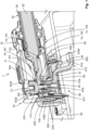
- Fig. 1 shows an entity 0 which is electrically contactable by the line connector 1: 10, (20,) ...; 10, (20,) 10; ..., (20,) 10 according to the invention.
- the entity 0 comprises, for this purpose, a high-current mating connector 50, which in this case is set up as a socket 50 on the outside on entity 0.
- the high-current mating connector 50 comprises, in a housing 55, a preferably solid high-current mating contact device 51 (simply mating contact device 51 below) having a mating contact section 516.
- the mating contact section 516 is in this case designed to be substantially hollow-cylindrical, wherein the free end side of this (as far as possible) thick (current-carrying capacity) hollow cylinder forms a mating contact-making area 5160.
- the mating contact device 51 preferably comprises copper or aluminium.
- the mating contact section 516 protrudes in particular substantially perpendicularly away from a mechanical mating clamping section 514 of the mating contact device 51, which mating clamping section 514 preferably merges integrally with a mating contact section 512 of the mating contact device 51 for a high-current line.
- the mating clamping section 514 and the mating contact section 516 with the mating contact-making area 5160 comprise a (coaxial) through recess 513 (preferably with a constant diameter) in the mating contact device 51, in which a mechanical mating clamping screw device 52 can be accommodated.
- Other configurations of the mating contact device 51 can naturally be used.
- the mating clamping screw device 52 is in this case in the form of a threaded sleeve having a mating screw head 610 and a mating screw body 620 which axially Ar adjoins the said mating screw head and has an internal thread.
- An external thread can naturally also be used in another embodiment.
- a ring-shaped touch guard 632 is arranged on a free end of the mating screw body 620.
- the mating screw head 610 rests with a chin 611 opposite the mating contact section 516 on the mating clamping section 514 of the mating contact device 51 and prevents the mating clamping screw device 52 from being able to be plugged through the through recess 513 in the mating contact device 51.
- Electrical contact can be made with the electrical mating contact-making area 5160 by a contacting surface 1160 of a contact section 116 of a preferably solid high-current contact device 11 (simply contact device 11 below) of the high-current connector 10.
- the contact section 116 protrudes in particular substantially perpendicularly away from a mechanical clamping section 114 of the contact device 11, which clamping section 114 preferably merges integrally with a contact section 112 of the contact device 11 for a high-current line 22.
- the contact device 11 preferably comprises copper or aluminium.
- the high-current line 22 can for all embodiments be in the form of, for example, a (rigid) conductor bar, a busbar, a (limitedly flexible) stranded conductor line etc. and preferably comprises aluminium or copper.
- the contact section 116 is in this case, similarly to the mating contact section 516, designed to be substantially hollow-cylindrical, wherein the free end side of this (as far as possible) thick (current-carrying capacity) hollow cylinder forms the contacting surface 1160.
- the clamping section 514 and the contact section 516 with the contacting surface 1160 comprise a (coaxial) through recess 113 in the contact device 11, in which the mechanical clamping screw device 12 can be accommodated.
- the through recess 113 can be designed to be stepped, wherein the through recess 113 has a smaller radius in the clamping section 114, for centring reasons (screw body 220, cf.
- a high-current line 22 preferably of a high-current line connection 20 is electrically connected to the contact section 112 of the contact device 11 of the high-current connector 10, wherein the high-current line connection 20 preferably comprises an electromagnetic shielding 24, which is arranged between two layers of electrical insulation of the high-current line connection 20 (cf. Fig. 1 ).
- the line connector 1 according to the invention comprises at least one high-current connector 10 according to the invention having an embodiment according to the invention of the clamping screw device 12.
- the line connector 1 can comprise, in addition to the one high-current connector 10 according to the invention, a second high-current connector (10), which is designed in accordance with the invention [10, (20,) 10; ...] or not [10, (20,) ...; ..., (20,) 10] in accordance with the invention.
- a high-current line connection 20 it is naturally also possible for a high-current line connection 20 to be used which is different from the one illustrated.
- the contact device 11 is preferably accommodated with the high-current line 22, which is preferably materially integrally fixed thereto, in an electrically insulating cladding 13.
- the transition region to the high-current line 22 and therefore a longitudinal end section of the high-current line 22 is also accommodated in the insulating cladding 13.
- the insulating cladding 13 can comprise two cladding parts 131, 132, in particular an upper cladding part 131 and a lower cladding part 132.
- an electromagnetic shielding 14 of the high-current connector 10 is arranged on the outside on the electrically insulating cladding 13, wherein this electromagnetic shielding 14 makes electrical contact with the electromagnetic shielding 24 of the high-current line 22.
- electrical contact is made with the electromagnetic shielding 14 of the high-current connector 10 by an electromagnetic shielding of the high-current mating connector 50 in a plugged-together state of the high-current connector 10 and the high-current mating connector 50.
- the electromagnetic shielding 14 can comprise two shield parts 141, 142, in particular an upper shield part 141 and a lower shield part 142.
- This stack comprising contact device 11, including longitudinal end section of the high-current line 22, its electrically insulating cladding 13 and its electromagnetic shielding 14 is preferably accommodated in a housing 15.
- the housing 15 comprises a through recess 153, in which the clamping screw device 12 is accommodated, preferably in anti-loss fashion (anti-loss means 1532, for example in the form of a cap with an access opening for a tool).
- An inner side 1530 of the through recess 153 can be in the form of a sealing face 1530 for a seal 216 of the clamping screw device 12.
- this can be designed conversely, i.e., the through recess 153 comprises a seal on the inside for the clamping screw device 12.
- the through recess 153 can be coverable by a protective cap 154.
- the protective cap 154 can be in the form of a protective cap slider 154.
- Another protective cap 154 for example a foldable protective cap, a separate protective cap etc., can naturally be used.
- the clamping screw device 12, cf. Figs 2 to 5 and in particular Figs 3 and 5 , in screwed-together interaction with the mating clamping screw device 52, serves the purpose of mechanically, permanently and fixedly clamping the contacting surface 1160 of the contact section 116 of the contact device 11 (responsible: clamping screw device 12) against the mating contact-making area 5160 of the mating contact section 516 of the mating contact device 51 (responsible: mating clamping screw device 52) for transmitting high electrical currents and voltages.
- clamping screw device 12 and the mating clamping screw device 52 are screwed to one another, wherein the clamping screw device 12 (external thread) is preferably screwed into the mating clamping screw device 52 (internal thread).
- the clamping screw device 12 external thread
- the mating clamping screw device 52 internal thread
- the contact section 116 and the mating contact section 516 are pressed one on top of the other and held fixedly against one another.
- the screw composite consisting of the clamping screw device 12 and the mating clamping screw device 52 extends through the through recesses 113, 513 in the contact section 116 and the mating contact section 516.
- the respective embodiment, cf. Fig. 3 and Fig. 5 , of the clamping screw device 12 comprises a clamping screw 200 in the form of a partially threaded screw 200 (bolt 200), which integrally comprises, one behind the other in the axial direction Ar, a screw head 210, a screw body 220 and preferably also an in particular pronounced screw foot 230.
- the screw foot 230 is in the form of a protrusion of the screw body 220 on which a touch guard 232 is provided.
- screw foot 230 for example in the form of a recess, in the screw body 220 and then to fit the touch guard 232 therein, which touch guard then sits in the screw foot 230 and protrudes away from the screw body 220.
- the screw body 220 in this case comprises a substantially smooth screw shank 222 for centring the clamping screw device 12 in the clamping section 114 of the contact device 11.
- the screw shank 222 merges with a threaded shank 224 having an external thread (possibly also internal thread), by means of which the clamping screw device 12 can be screwed into the mating clamping screw device 52.
- the screw head 210 rests with a chin 211 opposite the contact section 116 on the clamping section 114 and prevents the clamping screw device 12 from being able to be plugged through the through recess 113 in the contact device 11.
- the screw head 210 is at least partially, but preferably up to the chin 211, embedded in an electrical insulation 212, wherein the screw head 210 and the electrical insulation 212 form a fixed composite.
- the screw head 210 can in this case comprise an exclusively positive form (present material of the screw head 210, for example an outer n-sided profile or an analogue thereof, Fig. 3 ) or an additionally negative form (absent material of the screw head 210, for example an inner n-sided profile or an analogue thereof, Fig. 5 ).
- the screw head 210 can comprise, independently of its form, an electromagnetic shielding 214 and/or a seal 216.
- the electromagnetic shielding 214 can be embedded in the electrical insulation 212 or provided on the outside on the electrical insulation 212. In this case, the electromagnetic shielding 214 extends far in the axial direction Ar in the direction of the screw body 220 such that electrical contact can be made with the electromagnetic shielding 14 of the high-current connector 10. In this case, the shielding 214 can make direct electrical contact with the shielding 14 and/or an electrical contact can be produced with the aid of an additional component part therebetween, such as, for example, an EMC seal.
- the electromagnetic shielding 214 surrounds the electrical insulation 212 and/or the screw head 210 preferably completely in the circumferential direction Ur.
- the seal 216 is preferably provided over the full circumference in the circumferential direction Ur radially outwards on the screw head 210, wherein the seal 216 sits either on the electrical insulation 212 ( Fig. 3 ) or on the electromagnetic shielding 14 ( Fig. 5 ).
- the seal 216 can be a separate component part or can be connected in materially fixed fashion, in particular by means of an injection-moulding process, to the screw head 210 or to the electrical shielding 14.
- the screw head 210 of the clamping screw 200 of the first embodiment comprises an outer profile which merges with a collar radially Rr outwards on the screw shank 222 and whose lower rim forms the chin 211.
- the electrical insulation 212 is provided on the outside on this outer profile, wherein a circumferential wall 2120 of the electrical insulation 212 surrounds the electrically insulated screw head 210 preferably completely in the circumferential direction Ur with a radial Rr spacing.
- the circumferential wall 2120 imparts a pot shape to the electrical insulation 212.
- a seal 216 is arranged on a radial Rr circumferential surface 2122 of the circumferential wall 2120, wherein preferably at least one sealing lip of the seal 216 protrudes radially Rr outwards.
- the clamping screw device 12 can be sealed against the sealing surface 1530 of the through recess 153 in the housing 15 by means of the seal 216 and the electrical insulation 212.
- an electromagnetic shielding 214 can be used.
- the screw head 210 of the clamping screw 200 of the second embodiment comprises a pot-shaped inner profile which merges with a collar radially Rr outwards on the screw shank 222 and whose lower rim forms the chin 211.
- the electrical insulation 212 is arranged on the inside, on the end side and on the outside on this inner profile, wherein an outer circumferential wall 2120 of the electrical insulation 212 rests directly on an outside of the pot-shaped inner profile.
- the electromagnetic shielding 214 is arranged on a radial Rr circumferential surface 2122 of the circumferential wall 2120, an axial Ar end side of the electrical insulation 212 and an inner wall of the electrical insulation 212 in the inner profile.
- a seal 216 is arranged on a radial Rr circumferential surface 2142 of the electromagnetic shielding 214, wherein preferably at least one sealing lip of the seal 216 protrudes radially Rr outwards.
- the clamping screw device 12 can be sealed against the sealing surface 1530 of the through recess 153 in the housing 15 by means of the seal 216 and the electrical insulation 212.
- the electromagnetic shielding 214 can be omitted.
Landscapes
- Chemical & Material Sciences (AREA)
- Chemical Kinetics & Catalysis (AREA)
- Electrochemistry (AREA)
- General Chemical & Material Sciences (AREA)
- Engineering & Computer Science (AREA)
- Manufacturing & Machinery (AREA)
- Connections By Means Of Piercing Elements, Nuts, Or Screws (AREA)
- Details Of Connecting Devices For Male And Female Coupling (AREA)
- Connector Housings Or Holding Contact Members (AREA)
- Battery Mounting, Suspending (AREA)
- Connection Of Batteries Or Terminals (AREA)
- Connection Of Plates (AREA)
Applications Claiming Priority (2)
| Application Number | Priority Date | Filing Date | Title |
|---|---|---|---|
| DE102021123635.5A DE102021123635A1 (de) | 2021-09-13 | 2021-09-13 | Hochstromverbindungs-Spannschraubenvorrichtung sowie elektrischer Hochstromverbinder und Hochstrom-Leitungsverbinder |
| EP22195273.2A EP4148910B1 (de) | 2021-09-13 | 2022-09-13 | Hochstrom-verbindungs-klemmschraubenvorrichtung sowie elektrischer hochstromverbinder und hochstromleitungsverbinder |
Related Parent Applications (2)
| Application Number | Title | Priority Date | Filing Date |
|---|---|---|---|
| EP22195273.2A Division-Into EP4148910B1 (de) | 2021-09-13 | 2022-09-13 | Hochstrom-verbindungs-klemmschraubenvorrichtung sowie elektrischer hochstromverbinder und hochstromleitungsverbinder |
| EP22195273.2A Division EP4148910B1 (de) | 2021-09-13 | 2022-09-13 | Hochstrom-verbindungs-klemmschraubenvorrichtung sowie elektrischer hochstromverbinder und hochstromleitungsverbinder |
Publications (2)
| Publication Number | Publication Date |
|---|---|
| EP4395090A2 true EP4395090A2 (de) | 2024-07-03 |
| EP4395090A3 EP4395090A3 (de) | 2024-09-25 |
Family
ID=83319182
Family Applications (2)
| Application Number | Title | Priority Date | Filing Date |
|---|---|---|---|
| EP24176110.5A Pending EP4395090A3 (de) | 2021-09-13 | 2022-09-13 | Hochstrom-verbindungs-klemmschraubenvorrichtung sowie elektrischer hochstromverbinder und hochstromleitungsverbinder |
| EP22195273.2A Active EP4148910B1 (de) | 2021-09-13 | 2022-09-13 | Hochstrom-verbindungs-klemmschraubenvorrichtung sowie elektrischer hochstromverbinder und hochstromleitungsverbinder |
Family Applications After (1)
| Application Number | Title | Priority Date | Filing Date |
|---|---|---|---|
| EP22195273.2A Active EP4148910B1 (de) | 2021-09-13 | 2022-09-13 | Hochstrom-verbindungs-klemmschraubenvorrichtung sowie elektrischer hochstromverbinder und hochstromleitungsverbinder |
Country Status (5)
| Country | Link |
|---|---|
| EP (2) | EP4395090A3 (de) |
| JP (1) | JP7434474B2 (de) |
| KR (1) | KR102907105B1 (de) |
| CN (1) | CN115810926A (de) |
| DE (2) | DE102021123635A1 (de) |
Families Citing this family (9)
| Publication number | Priority date | Publication date | Assignee | Title |
|---|---|---|---|---|
| DE102022206634A1 (de) * | 2022-06-30 | 2024-01-04 | Robert Bosch Gesellschaft mit beschränkter Haftung | Hochvoltschnittstelle |
| DE102022120762A1 (de) * | 2022-08-17 | 2024-02-22 | Te Connectivity Germany Gmbh | Elektrischer Hochstromverbinder |
| DE102023114718A1 (de) * | 2023-06-05 | 2024-12-05 | Te Connectivity Solutions Gmbh | Hochstromverbinder und Modulverbindersystem mit solch einem Hochstromverbinder |
| DE102023118395B4 (de) * | 2023-07-12 | 2025-01-23 | Schaeffler Technologies AG & Co. KG | Elektrische Hochvoltverbindung und Elektrisch betreibbarer Antriebsstrang eines Kraftfahrzeugs |
| DE102023119845B3 (de) | 2023-07-26 | 2024-10-10 | Amphenol-Tuchel Electronics Gesellschaft mit beschränkter Haftung | Stromschiene-Steckkontaktpin-Verbindung |
| DE102023132002A1 (de) * | 2023-11-16 | 2025-05-22 | Te Connectivity Solutions Gmbh | Berührgeschütztes Kontaktteil |
| DE102023134836A1 (de) * | 2023-12-12 | 2025-06-12 | Lisa Dräxlmaier GmbH | Konfektionierte leitung und verfahren zum konfektionieren einer leitung |
| JP7839208B2 (ja) * | 2024-02-08 | 2026-04-01 | 矢崎総業株式会社 | コネクタユニットおよびワイヤハーネス |
| DE102024118568B4 (de) * | 2024-07-01 | 2026-03-19 | Lisa Dräxlmaier GmbH | Stecksystem |
Citations (5)
| Publication number | Priority date | Publication date | Assignee | Title |
|---|---|---|---|---|
| US20120231676A1 (en) | 2009-11-23 | 2012-09-13 | Tyco Electronics France Sas | Casing for an electrical connector |
| DE102015216543A1 (de) | 2015-08-28 | 2017-03-02 | Te Connectivity Germany Gmbh | Kontaktanordnung, Stecker und Steckverbindung |
| CN206650178U (zh) | 2017-03-16 | 2017-11-17 | 深圳市沃尔核材股份有限公司 | 电缆的连接器结构 |
| US20180294600A1 (en) | 2017-04-11 | 2018-10-11 | Yazaki Europe Ltd | Electric connection arrangement |
| GB2588769A (en) | 2019-11-04 | 2021-05-12 | Jaguar Land Rover Ltd | Terminal fasteners for traction batteries |
Family Cites Families (10)
| Publication number | Priority date | Publication date | Assignee | Title |
|---|---|---|---|---|
| JP4650691B2 (ja) * | 2006-03-03 | 2011-03-16 | 住友電装株式会社 | 電気接続構造 |
| KR101156449B1 (ko) * | 2009-02-25 | 2012-06-13 | 고은애 | 케이블용 단자커넥터 |
| US8287320B2 (en) * | 2009-05-22 | 2012-10-16 | John Mezzalingua Associates, Inc. | Coaxial cable connector having electrical continuity member |
| JP2012256573A (ja) * | 2011-06-10 | 2012-12-27 | Toyota Motor Corp | コネクタ接続構造 |
| DE102014102659A1 (de) * | 2014-02-28 | 2015-09-03 | Phoenix Contact Gmbh & Co. Kg | Mantelklemme zum Herstellen eines elektrischen Kontakts |
| DE102014216281A1 (de) * | 2014-08-15 | 2016-02-18 | Robert Bosch Gmbh | Steckverbinder für die Übertragung von Hochvoltstrom im Kfz-Bereich |
| DE102014012350B3 (de) * | 2014-08-25 | 2015-12-10 | Sew-Eurodrive Gmbh & Co Kg | Anschlussanordnung für ein elektrisches Gerät |
| DE102015216545A1 (de) * | 2015-08-28 | 2017-03-02 | Te Connectivity Germany Gmbh | Gehäuseanordnung, elektrischer Verbinder umfassend eine Gehäuseanordnung und elektrische Verbindungsanordnung umfassend einen elektrischen Verbinder |
| CN106898887B (zh) * | 2017-03-16 | 2024-11-29 | 深圳市沃尔新能源电气科技股份有限公司 | 电缆的连接器结构 |
| CN111384347B (zh) | 2018-12-29 | 2022-08-30 | 东莞莫仕连接器有限公司 | 电池连接模块 |
-
2021
- 2021-09-13 DE DE102021123635.5A patent/DE102021123635A1/de active Pending
-
2022
- 2022-09-07 KR KR1020220113602A patent/KR102907105B1/ko active Active
- 2022-09-08 CN CN202211100188.8A patent/CN115810926A/zh active Pending
- 2022-09-08 JP JP2022142634A patent/JP7434474B2/ja active Active
- 2022-09-13 DE DE202022002931.4U patent/DE202022002931U1/de active Active
- 2022-09-13 EP EP24176110.5A patent/EP4395090A3/de active Pending
- 2022-09-13 EP EP22195273.2A patent/EP4148910B1/de active Active
Patent Citations (5)
| Publication number | Priority date | Publication date | Assignee | Title |
|---|---|---|---|---|
| US20120231676A1 (en) | 2009-11-23 | 2012-09-13 | Tyco Electronics France Sas | Casing for an electrical connector |
| DE102015216543A1 (de) | 2015-08-28 | 2017-03-02 | Te Connectivity Germany Gmbh | Kontaktanordnung, Stecker und Steckverbindung |
| CN206650178U (zh) | 2017-03-16 | 2017-11-17 | 深圳市沃尔核材股份有限公司 | 电缆的连接器结构 |
| US20180294600A1 (en) | 2017-04-11 | 2018-10-11 | Yazaki Europe Ltd | Electric connection arrangement |
| GB2588769A (en) | 2019-11-04 | 2021-05-12 | Jaguar Land Rover Ltd | Terminal fasteners for traction batteries |
Also Published As
| Publication number | Publication date |
|---|---|
| US20230084743A1 (en) | 2023-03-16 |
| KR20230039562A (ko) | 2023-03-21 |
| JP7434474B2 (ja) | 2024-02-20 |
| KR102907105B1 (ko) | 2025-12-31 |
| EP4148910B1 (de) | 2025-11-19 |
| CN115810926A (zh) | 2023-03-17 |
| EP4395090A3 (de) | 2024-09-25 |
| DE202022002931U1 (de) | 2024-01-19 |
| EP4148910A1 (de) | 2023-03-15 |
| DE102021123635A1 (de) | 2023-03-16 |
| JP2023041645A (ja) | 2023-03-24 |
Similar Documents
| Publication | Publication Date | Title |
|---|---|---|
| EP4148910B1 (de) | Hochstrom-verbindungs-klemmschraubenvorrichtung sowie elektrischer hochstromverbinder und hochstromleitungsverbinder | |
| EP4325670A1 (de) | Elektrischer hochstromverbinder | |
| CN101373820B (zh) | 电池包 | |
| US10128722B2 (en) | Electrical connection structure, terminal structure, and vehicle | |
| CN109478627A (zh) | 导体组件和可移动电驱动装置 | |
| US10666002B2 (en) | Wiring harness connecting structure for housed circuit assembly | |
| WO2018013404A1 (en) | Terminals of an electrochemical cell | |
| US20190315238A1 (en) | High voltage battery for a motor vehicle | |
| US12620757B2 (en) | High-current connection clamping screw device as well as electrical high-current connector and high-current line connector | |
| JP7771147B2 (ja) | 車両のアセンブリのためのシールド電気アセンブリコネクタ | |
| US5814912A (en) | Electrical lead bushing for a turbine generator | |
| JP7708520B2 (ja) | 耐振動性電気的平型メス端子 | |
| WO2024198864A1 (zh) | 一种便于更换线缆的充电座 | |
| US11990254B2 (en) | High-voltage cable distributor | |
| CN117810741A (zh) | 分体式连接器 | |
| JP2024101560A (ja) | タッチ保護手段を有する高電圧タブコンタクト手段および高電圧コネクタ | |
| CN104466542A (zh) | 用于屏蔽高电压的电连接器 | |
| US20240208340A1 (en) | Charge inlet | |
| JP7540414B2 (ja) | 雌端子及び端子接続構造 | |
| CN115697810B (zh) | 高功率插接连接器系统 | |
| WO2025154960A1 (ko) | 차량용 변압기 | |
| CN205406606U (zh) | 具有防电弧式接线柱的电池箱 | |
| KR19990025360A (ko) | 전기자동차용 밧데리 구조 | |
| CN119171113A (zh) | 一种双层端子 | |
| KR20250070570A (ko) | 전기 고전압 커넥터 및 전기 고전압 연결부를 장착하기 위한 방법 |
Legal Events
| Date | Code | Title | Description |
|---|---|---|---|
| PUAI | Public reference made under article 153(3) epc to a published international application that has entered the european phase |
Free format text: ORIGINAL CODE: 0009012 |
|
| STAA | Information on the status of an ep patent application or granted ep patent |
Free format text: STATUS: REQUEST FOR EXAMINATION WAS MADE |
|
| 17P | Request for examination filed |
Effective date: 20240515 |
|
| AC | Divisional application: reference to earlier application |
Ref document number: 4148910 Country of ref document: EP Kind code of ref document: P |
|
| AK | Designated contracting states |
Kind code of ref document: A2 Designated state(s): AL AT BE BG CH CY CZ DE DK EE ES FI FR GB GR HR HU IE IS IT LI LT LU LV MC MK MT NL NO PL PT RO RS SE SI SK SM TR |
|
| REG | Reference to a national code |
Ref country code: DE Ref legal event code: R079 Free format text: PREVIOUS MAIN CLASS: H02G0003000000 Ipc: H01R0004340000 |
|
| PUAL | Search report despatched |
Free format text: ORIGINAL CODE: 0009013 |
|
| AK | Designated contracting states |
Kind code of ref document: A3 Designated state(s): AL AT BE BG CH CY CZ DE DK EE ES FI FR GB GR HR HU IE IS IT LI LT LU LV MC MK MT NL NO PL PT RO RS SE SI SK SM TR |
|
| RIC1 | Information provided on ipc code assigned before grant |
Ipc: H02G 3/00 20060101ALI20240820BHEP Ipc: B60R 16/00 20060101ALI20240820BHEP Ipc: H01R 13/6581 20110101ALI20240820BHEP Ipc: H01R 11/26 20060101ALI20240820BHEP Ipc: H01R 4/34 20060101AFI20240820BHEP |
|
| GRAP | Despatch of communication of intention to grant a patent |
Free format text: ORIGINAL CODE: EPIDOSNIGR1 |
|
| STAA | Information on the status of an ep patent application or granted ep patent |
Free format text: STATUS: GRANT OF PATENT IS INTENDED |
|
| GRAJ | Information related to disapproval of communication of intention to grant by the applicant or resumption of examination proceedings by the epo deleted |
Free format text: ORIGINAL CODE: EPIDOSDIGR1 |
|
| STAA | Information on the status of an ep patent application or granted ep patent |
Free format text: STATUS: REQUEST FOR EXAMINATION WAS MADE |
|
| INTG | Intention to grant announced |
Effective date: 20260313 |
|
| INTC | Intention to grant announced (deleted) |