EP4395618B1 - Réglage d'une position d'au moins un élément de travail dans un agencement de buse - Google Patents
Réglage d'une position d'au moins un élément de travail dans un agencement de buse Download PDFInfo
- Publication number
- EP4395618B1 EP4395618B1 EP22769647.3A EP22769647A EP4395618B1 EP 4395618 B1 EP4395618 B1 EP 4395618B1 EP 22769647 A EP22769647 A EP 22769647A EP 4395618 B1 EP4395618 B1 EP 4395618B1
- Authority
- EP
- European Patent Office
- Prior art keywords
- nozzle arrangement
- working member
- value
- pushing force
- push
- Prior art date
- Legal status (The legal status is an assumption and is not a legal conclusion. Google has not performed a legal analysis and makes no representation as to the accuracy of the status listed.)
- Active
Links
Images

Classifications
-
- A—HUMAN NECESSITIES
- A47—FURNITURE; DOMESTIC ARTICLES OR APPLIANCES; COFFEE MILLS; SPICE MILLS; SUCTION CLEANERS IN GENERAL
- A47L—DOMESTIC WASHING OR CLEANING; SUCTION CLEANERS IN GENERAL
- A47L9/00—Details or accessories of suction cleaners, e.g. mechanical means for controlling the suction or for effecting pulsating action; Storing devices specially adapted to suction cleaners or parts thereof; Carrying-vehicles specially adapted for suction cleaners
- A47L9/02—Nozzles
- A47L9/04—Nozzles with driven brushes or agitators
- A47L9/0461—Dust-loosening tools, e.g. agitators, brushes
- A47L9/0466—Rotating tools
- A47L9/0477—Rolls
-
- A—HUMAN NECESSITIES
- A47—FURNITURE; DOMESTIC ARTICLES OR APPLIANCES; COFFEE MILLS; SPICE MILLS; SUCTION CLEANERS IN GENERAL
- A47L—DOMESTIC WASHING OR CLEANING; SUCTION CLEANERS IN GENERAL
- A47L9/00—Details or accessories of suction cleaners, e.g. mechanical means for controlling the suction or for effecting pulsating action; Storing devices specially adapted to suction cleaners or parts thereof; Carrying-vehicles specially adapted for suction cleaners
- A47L9/02—Nozzles
- A47L9/06—Nozzles with fixed, e.g. adjustably fixed brushes or the like
- A47L9/066—Nozzles with fixed, e.g. adjustably fixed brushes or the like with adjustably mounted brushes, combs, lips or pads; Height adjustment of nozzle or dust loosening tools
Definitions
- the invention relates to a nozzle arrangement configured to be applied in a cleaning device and to be used in a cleaning action on a surface, wherein the nozzle arrangement: is configured to be moved forward and backward in an advancement direction of the nozzle arrangement over the surface, comprises at least one working member configured to assume one of at least two possible positions on the nozzle arrangement, and comprises a member setting mechanism configured to automatically set the position of the at least one working member.
- the invention relates to a vacuum cleaner comprising a nozzle arrangement as mentioned, which vacuum cleaner may be a cordless vacuum cleaner and/or a stick vacuum cleaner.
- Vacuum cleaners are known for removing dirt from a surface to be cleaned.
- the term "dirt" as used in the present text is to be understood so as to cover any contamination as may be present on a surface and that can be removed under the influence of a vacuum cleaning action, probably combined with another cleaning action such as mopping. Practical examples in this respect include dust and small particles of any kind, and also wet types of contamination such as spilled drinks.
- a practical example of the surface to be cleaned is a floor, wherein the floor may be of any kind, such as a wooden floor, a carpet floor, a tile floor, etc.
- a vacuum cleaner has a vacuum cleaner head, which is commonly referred to by terms such as suction head, suction nozzle, or nozzle arrangement. In the present text, the latter term will be used.
- the nozzle arrangement is the part of the vacuum cleaner where the actual process of picking up dirt from a surface to be cleaned is to take place and which is therefore to be put on or at least close to the surface.
- a vacuum cleaner normally comprises a body portion including a dirt accumulating area and an arrangement configured to act on the nozzle arrangement so that a suction force is prevailing in the nozzle arrangement during operation of the vacuum cleaner. The suction force serves to facilitate transport of dirt that is picked up from the surface during operation of the vacuum cleaner towards the dirt accumulating area.
- the suction force may also have a function in the actual process of picking up the dirt from the surface.
- the nozzle arrangement may be equipped with at least one movable component for interacting with the surface in order to pick up the dirt, such as at least one rotatable brush that may serve as an agitator of the dirt and that may particularly be configured to help dislodge dirt from the surface and direct it to further inside the nozzle arrangement.
- the working member for cleaning rugs/carpets is realized as a smooth operating member and the working member for cleaning hard floors is realized as a brush operating member.
- the smooth operating member automatically functions to perform cleaning when the flow of air in its path of flow between the suction inlet and outlet of the nozzle is at or less than a predetermined speed
- the brush operating member automatically functions to perform cleaning when the flow of air exceeds the predetermined speed.
- a type of working member which is especially configured to interact with a soft floor such as a carpet floor, and which should not be allowed to contact a hard floor in order to avoid damage to the hard floor in the form of scratches, for example.
- Nozzle arrangements are known which are configured to enable manual setting of the position of the working member, in which case appropriate action by a user is required, depending on the type of the surface to be cleaned. There is a risk that the user forgets to switch the position of the working member when another type of surface is to be cleaned, or that the user is confused about which position of the working member should go with which position of the working member and sets an incorrect position of the working member for that reason.
- nozzle arrangements are known in which the underpressure prevailing in the nozzle arrangement when the nozzle arrangement is used on a hard floor is used to lift the working member off the floor.
- the problems involved in dependency on user action are alleviated, but the fact is that relying on underpressure effects is not possible/suitable in all possible situations.
- the level of underpressure is insufficient to realize the desired setting of the working member.
- the constructions enabling use of underpressure to bring about movement of the working member require a lot of space in the nozzle arrangements and thereby significantly add to bulkiness of the nozzle arrangements.
- the invention provides a nozzle arrangement configured to be applied in a cleaning device and to be used in a cleaning action on a surface, wherein the nozzle arrangement: is configured to be moved forward and backward in an advancement direction of the nozzle arrangement over the surface, comprises at least one working member configured to assume one of at least two possible positions on the nozzle arrangement, and comprises a member setting mechanism configured to automatically set the position of the at least one working member in relation to a value of at least one discrimination parameter that is influenced by motion resistance between the nozzle arrangement and an actual surface.
- the member setting mechanism functions on the basis of another principle than using underpressure for determining the position of the at least one working member.
- the invention covers various types of working member.
- the at least one working member is configured to assume at least one active position at which the at least one working member is capable of influencing interaction between the nozzle arrangement and the surface, and an inactive position, i.e. a position at which the at least one working member is not capable of doing so. It may be so that the at least one working member is in a position for contacting the surface when the at least one working member is in the at least one active position, although this is not essential in the context of the invention.
- the member setting mechanism is configured to put the at least one working member from the inactive position to an active position when the value of the at least one discrimination parameter exceeds a reference value.
- such a reference value may be between a value of the at least one discrimination parameter related to movement of the nozzle arrangement over a hard surface and a value of the at least one discrimination parameter related to movement of the nozzle arrangement over a soft surface providing higher motion resistance than the hard surface.
- the nozzle arrangement is configured to be moved forward and backward in the advancement direction of the nozzle arrangement over the surface under the influence of an external pushing force and an external pulling force, respectively, and the at least one discrimination parameter is a parameter representative of the external pushing force.
- the external pushing force and the external pulling force may particularly be exerted by a user.
- the nozzle arrangement comprises at least one rotatable brush configured to interact with the surface, and a motor configured to drive the brush, and the at least one discrimination parameter is a parameter representative of power consumption of the motor.
- the user takes hold of an appropriate portion of the cleaning device to which the nozzle arrangement 1 is coupled, which may be a handle on a body portion of the cleaning device in case the cleaning device is a stick vacuum cleaner or a grip portion on a hose of the cleaning device in case the cleaning device is a canister vacuum cleaner, and manipulates this portion so that the movement of the nozzle arrangement 1 on the surface 2 as desired is realized.
- an appropriate portion of the cleaning device to which the nozzle arrangement 1 is coupled which may be a handle on a body portion of the cleaning device in case the cleaning device is a stick vacuum cleaner or a grip portion on a hose of the cleaning device in case the cleaning device is a canister vacuum cleaner, and manipulates this portion so that the movement of the nozzle arrangement 1 on the surface 2 as desired is realized.
- the nozzle arrangement 1 is equipped with a ramp element 30 as a working member that is configured to assume one of at two possible positions on the nozzle arrangement 1, namely a lowered position as shown in figure 1 , which is an active position of the ramp element 30, and a raised position as shown in figure 2 , which is an inactive position of the ramp element 30.
- the ramp element 30 is arranged at a side of the nozzle arrangement 1 that is a front side in the advancement direction d a . At the active position, the ramp element 30 acts to limit air flow from the front side of the nozzle arrangement 1 to the nozzle arrangement 1. In this way, pressure loss which would otherwise occur under the influence of the interaction with a porous soft surface is prevented, so that dirt removal from such a type of surface is not compromised.
- the nozzle arrangement 1 is equipped with a member setting mechanism 40 that is configured to ensure that the position of the ramp element 30 is always appropriate in view of the type of surface 2 to be cleaned.
- the member setting mechanism 40 is particularly configured to automatically set the position of the ramp element 30 under the influence of the forces exerted by the user for moving the nozzle arrangement 1 across the surface 2 during a cleaning action as will now be explained.
- the housing 10 of the nozzle arrangement 1 comprises two portions which are movable relative to each other to some extent, one of those housing portions being associated with the coupling area 11 and the other of those housing portions being associated with the brush area 13.
- the ramp element 30 is coupled to the housing portion associated with the coupling area 11 through a hinging construction 41.
- a resilient element 42 which is a coil spring in the shown example, is arranged between the two housing portions. In a default situation without any force being exerted on the housing portion associated with the coupling area 11, the resilient element 42 acts to push the housing portions apart to such an extent that the hinging construction 41 is in a position for realizing the raised, inactive position of the ramp element 30.
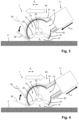
- the characteristics of the resilient element 42 are chosen such that when a pushing force F push is exerted on the portion associated with the coupling area 11, as illustrated in figure 3 , this pushing force F push acts to realize forward movement of the nozzle arrangement 1 on the surface 2 without forcing movement of the ramp element 30 from the inactive position to the active position as long as the value of this pushing force F push is lower than a value of a counterforce exerted by the resilient element 42, and acts to realize forward movement of the nozzle arrangement 1 on the surface 2 while also forcing movement of the ramp element 30 from the inactive position to the active position when the value of this pushing force F push exceeds a value of the counterforce, as indicated in figure 3 by means of a curved arrow.
- the ramp element 30 in the active position is depicted in continuous lines and the ramp element 30 in the inactive position is depicted in dashed lines.
- this pulling force F pull acts to realize backward movement of the nozzle arrangement 1 on the surface 2.
- movement of the ramp element 30 back from the active position to the inactive position takes place under the influence of action of the resilient element 42, as indicated in figure 4 by means of a curved arrow.
- the ramp element 30 in the active position is depicted in dashed lines and the ramp element 30 in the inactive position is depicted in continuous lines.
- the ramp element 30 is continuously kept in the inactive position when the pushing force F push that is exerted on the nozzle arrangement 1 during the forward movement is lower than a counterforce exerted by the resilient element 42.
- the member setting mechanism 40 acts to move the ramp element 30 from the inactive position to the active position.
- the ramp element 30 is automatically lowered during the forward movement and raised during the backward movement.
- an area of friction that is present between the nozzle arrangement 1 and the surface 2 as the nozzle arrangement 1 is moved on the surface 2, i.e. an area in which the motion resistance is of influence, is indicated in figures 3 and 4 , as a box A f delimited by dashed lines.
- the active position of the ramp element 30 is only obtained when the nozzle arrangement 1 is used on a surface 2 of the soft type, and the inactive position of the ramp element 30 is ensured in respect of a surface 2 of the hard type, as desired.
- nozzle arrangement 1 it is possible to add features to the nozzle arrangement 1 to enable locking the position of the ramp element 30. By locking the ramp element 30 in the active position, optimal soft surface performance in backward movement can be ensured because when the ramp element 30 stays down, a higher underpressure can be created in the nozzle arrangement 1.
- Other benefits of having locking features may include prevention of unintentional switching on high friction hard surfaces or when bumping into obstacles, or to ensure proper switching on low friction soft floors.
- the member setting mechanism 40 as illustrated in figures 3 and 4 and described in the foregoing is configured to operate in a purely mechanical fashion. That does not alter the fact that the invention also covers embodiments of the nozzle arrangement 1 in which the member setting mechanism 40 acts on the basis of other principles, including principles involving use of an electric detection and control system.
- a nozzle arrangement 1 In the field of cleaning surfaces, a nozzle arrangement 1 is provided that is configured to be applied in a cleaning device and to be moved forward and backward in an advancement direction d a of the nozzle arrangement 1 over a surface 2.
- the nozzle arrangement 1 comprises at least one working member 30 configured to assume one of at least two possible positions on the nozzle arrangement 1, and a member setting mechanism 40 configured to automatically set the position of the at least one working member 30 in relation to a value of at least one discrimination parameter that is influenced by motion resistance between the nozzle arrangement 1 and an actual surface 2. In that way, automatic setting of the position of the at least one working element 30 in relation to the surface type is achieved.
Landscapes
- Engineering & Computer Science (AREA)
- Mechanical Engineering (AREA)
- Nozzles For Electric Vacuum Cleaners (AREA)
Claims (15)
- Agencement de buse (1) configuré pour être appliqué dans un dispositif de nettoyage et pour être utilisé lors d'une action de nettoyage sur une surface (2), dans lequel l'agencement de buse (1) :- est configuré pour être déplacé vers l'avant et vers l'arrière dans une direction d'avancement (da) de l'agencement de buse (1) sur la surface (2), et- comprend au moins un élément de travail (30) configuré pour adopter l'une d'au moins deux positions possibles sur l'agencement de buse (1),caractérisé en ce que l'agencement de buse comprend un mécanisme de réglage d'élément (40) configuré pour régler automatiquement la position du au moins un élément de travail (30) par rapport à une valeur d'au moins un paramètre de discrimination qui est influencé par la résistance au mouvement entre l'agencement de buse (1) et une surface réelle (2).
- Agencement de buse (1) selon la revendication 1, dans lequel le au moins un élément de travail (30) est configuré pour adopter au moins une position active dans laquelle le au moins un élément de travail (30) est capable d'influencer l'interaction entre l'agencement de buse (1) et la surface (2), et une position inactive.
- Agencement de buse (1) selon la revendication 2, dans lequel le mécanisme de réglage d'élément (40) est configuré pour amener le au moins un élément de travail (30) de la position inactive à une position active lorsque la valeur du au moins un paramètre de discrimination dépasse une valeur de référence.
- Agencement de buse (1) selon la revendication 3, dans lequel la valeur de référence est comprise entre une valeur du au moins un paramètre de discrimination lié au mouvement de l'agencement de buse (1) sur une surface dure (2) et une valeur du au moins un paramètre de discrimination lié au mouvement de l'agencement de buse (1) sur une surface molle (2) offrant une résistance au mouvement plus élevée que la surface dure (2).
- Agencement de buse (1) selon l'une quelconque des revendications 1-4, dans lequel l'agencement de buse (1) est configuré pour être déplacé vers l'avant et vers l'arrière dans la direction d'avancement (da) de l'agencement de buse (1) sur la surface (2) sous l'influence d'une force de poussée externe (Fpoussée) et d'une force de traction externe (Ftraction), respectivement, et dans lequel le au moins un paramètre de discrimination est un paramètre représentatif de la force de poussée externe (Fpoussée).
- Agencement de buse (1) selon l'une quelconque des revendications 1-5, comprenant au moins une brosse rotative (20) configurée pour interagir avec la surface (2), et un moteur configuré pour entraîner la brosse (20), dans lequel le au moins un paramètre de discrimination est un paramètre représentatif de la consommation d'énergie du moteur.
- Agencement de buse (1) selon l'une quelconque des revendications 1-6, dans lequel le mécanisme de réglage d'élément (40) comprend un système capteur incluant un capteur configuré pour générer une sortie qui est représentative de la valeur du au moins un paramètre de discrimination et un dispositif de commande configuré pour recevoir la sortie du capteur et pour appliquer un algorithme conçu pour déterminer la position du au moins un élément de travail (30) à régler sur la base de la sortie du capteur.
- Agencement de buse (1) selon la revendication 5, dans lequel le système de réglage d'élément (40) comprend un système mécanique incluant un élément de réaction (42) configuré pour fournir une contre-force agissant contre la force de poussée externe (Fpoussée).
- Agencement de buse (1) selon la revendication 8, comprenant l'élément de travail (30) tel que défini dans la revendication 2, dans lequel l'élément de réaction (42) est configuré pour permettre au au moins un élément de travail (30) de rester dans la position inactive tant que la valeur de la force de poussée externe (Fpoussée) est inférieure à une valeur de la contre-force et pour permettre au au moins un élément de travail (30) de passer de la position inactive à une position active lorsque la valeur de la force de poussée externe (Fpoussée) dépasse la valeur de la contre-force.
- Agencement de buse (1) selon la revendication 9, dans lequel l'élément de réaction (42) est configuré pour permettre au au moins un élément de travail (30) de passer de la position active à la position inactive lorsque la valeur de la force de poussée externe (Fpoussée) tombe en dessous de la valeur de la contre-force.
- Agencement de buse (1) selon l'une quelconque des revendications 8-10, dans lequel l'élément de réaction (42) comprend au moins un élément élastique.
- Agencement de buse (1) selon l'une quelconque des revendications 1-11, comprenant un mécanisme de verrouillage configuré pour adopter l'une parmi une position pour verrouiller le au moins un élément de travail (30) en place et une position pour libérer le au moins un élément de travail (30).
- Agencement de buse (1) selon l'une quelconque des revendications 1-12, dans lequel le au moins un élément de travail (30) comprend un élément de rampe agencé sur un côté de l'agencement de buse (1) qui est un côté avant dans la direction d'avancement (da), et dans lequel l'élément de rampe (30) est mobile entre une position active dans laquelle l'élément de rampe (30) agit pour limiter le flux d'air depuis le côté avant de l'agencement de buse (1) vers l'agencement de buse (1), et une position inactive.
- Agencement de buse (1) selon l'une quelconque des revendications 1-13, configuré pour être appliqué dans un dispositif de nettoyage incluant une source d'aspiration d'air, et comprenant un boîtier (10) qui inclut une zone de couplage (11) configurée pour permettre le couplage du boîtier (10) à la source d'aspiration d'air du dispositif de nettoyage.
- Aspirateur, comprenant un ensemble de buse (1) selon l'une quelconque des revendications 1-14.
Applications Claiming Priority (2)
| Application Number | Priority Date | Filing Date | Title |
|---|---|---|---|
| EP21194418.6A EP4144272A1 (fr) | 2021-09-01 | 2021-09-01 | Réglage d'une position d'au moins un élément de travail dans un agencement de buse |
| PCT/EP2022/073844 WO2023031059A1 (fr) | 2021-09-01 | 2022-08-26 | Réglage d'une position d'au moins un élément de travail dans un agencement de buses |
Publications (2)
| Publication Number | Publication Date |
|---|---|
| EP4395618A1 EP4395618A1 (fr) | 2024-07-10 |
| EP4395618B1 true EP4395618B1 (fr) | 2025-04-09 |
Family
ID=77595478
Family Applications (2)
| Application Number | Title | Priority Date | Filing Date |
|---|---|---|---|
| EP21194418.6A Withdrawn EP4144272A1 (fr) | 2021-09-01 | 2021-09-01 | Réglage d'une position d'au moins un élément de travail dans un agencement de buse |
| EP22769647.3A Active EP4395618B1 (fr) | 2021-09-01 | 2022-08-26 | Réglage d'une position d'au moins un élément de travail dans un agencement de buse |
Family Applications Before (1)
| Application Number | Title | Priority Date | Filing Date |
|---|---|---|---|
| EP21194418.6A Withdrawn EP4144272A1 (fr) | 2021-09-01 | 2021-09-01 | Réglage d'une position d'au moins un élément de travail dans un agencement de buse |
Country Status (4)
| Country | Link |
|---|---|
| EP (2) | EP4144272A1 (fr) |
| CN (1) | CN117915816A (fr) |
| PL (1) | PL4395618T3 (fr) |
| WO (1) | WO2023031059A1 (fr) |
Family Cites Families (3)
| Publication number | Priority date | Publication date | Assignee | Title |
|---|---|---|---|---|
| SE353012B (fr) | 1971-02-26 | 1973-01-22 | Electrolux Ab | |
| US4447931A (en) * | 1980-12-03 | 1984-05-15 | Aktiebolaget Electrolux | Remotely controlled vacuum cleaner nozzle |
| EP2747625B1 (fr) * | 2011-08-23 | 2017-06-07 | Koninklijke Philips N.V. | Dispositif de nettoyage pour nettoyer une surface, comportant une brosse et un élément raclette |
-
2021
- 2021-09-01 EP EP21194418.6A patent/EP4144272A1/fr not_active Withdrawn
-
2022
- 2022-08-26 EP EP22769647.3A patent/EP4395618B1/fr active Active
- 2022-08-26 WO PCT/EP2022/073844 patent/WO2023031059A1/fr not_active Ceased
- 2022-08-26 PL PL22769647.3T patent/PL4395618T3/pl unknown
- 2022-08-26 CN CN202280058695.1A patent/CN117915816A/zh active Pending
Also Published As
| Publication number | Publication date |
|---|---|
| PL4395618T3 (pl) | 2025-06-02 |
| EP4144272A1 (fr) | 2023-03-08 |
| WO2023031059A1 (fr) | 2023-03-09 |
| CN117915816A (zh) | 2024-04-19 |
| EP4395618A1 (fr) | 2024-07-10 |
Similar Documents
| Publication | Publication Date | Title |
|---|---|---|
| US20260033681A1 (en) | Hand-held surface cleaning device | |
| US11612297B2 (en) | Autonomous floor cleaner with carry handle | |
| CN209884042U (zh) | 吸尘器保持器 | |
| EP3750464A1 (fr) | Robot nettoyeur | |
| EP2117402B1 (fr) | Dispositif de nettoyage du sol humide/sec | |
| US4766638A (en) | Four-way vacuum cleaner | |
| US8720004B2 (en) | Floor tool | |
| EP1795105B1 (fr) | Aspirateur | |
| CA2413401C (fr) | Aspirateur transformable | |
| US7131164B2 (en) | Vacuum cleaner and suction nozzle employed therein | |
| KR101487787B1 (ko) | 진공청소기용 흡입브러시 | |
| KR20090058917A (ko) | 청소기 | |
| KR101664686B1 (ko) | 청소기 | |
| EP4395618B1 (fr) | Réglage d'une position d'au moins un élément de travail dans un agencement de buse | |
| EP3030125B1 (fr) | Aspirateur comprenant un ensemble manche amovible | |
| US20240198397A1 (en) | Vacuum cleaner and method for operating a vacuum cleaner | |
| US10980381B1 (en) | Nozzle assembly for vacuum device | |
| US20240041293A1 (en) | Robotic vacuum cleaner, docking station, and cleaning system including the same | |
| US11786090B2 (en) | Floor nozzle for a vacuum cleaner and vacuum cleaner | |
| KR101208559B1 (ko) | 업라이트 형 진공청소기 | |
| EP2636349B1 (fr) | Dispositif d'aspiration pour aspirateur électrique et aspirateur électrique utilisant celui-ci | |
| EP2409618B1 (fr) | Aspirateur | |
| JP2005334209A (ja) | 掃除機用吸込具及びこれを用いた電気掃除機 |
Legal Events
| Date | Code | Title | Description |
|---|---|---|---|
| STAA | Information on the status of an ep patent application or granted ep patent |
Free format text: STATUS: UNKNOWN |
|
| STAA | Information on the status of an ep patent application or granted ep patent |
Free format text: STATUS: THE INTERNATIONAL PUBLICATION HAS BEEN MADE |
|
| PUAI | Public reference made under article 153(3) epc to a published international application that has entered the european phase |
Free format text: ORIGINAL CODE: 0009012 |
|
| STAA | Information on the status of an ep patent application or granted ep patent |
Free format text: STATUS: REQUEST FOR EXAMINATION WAS MADE |
|
| 17P | Request for examination filed |
Effective date: 20240402 |
|
| AK | Designated contracting states |
Kind code of ref document: A1 Designated state(s): AL AT BE BG CH CY CZ DE DK EE ES FI FR GB GR HR HU IE IS IT LI LT LU LV MC MK MT NL NO PL PT RO RS SE SI SK SM TR |
|
| GRAP | Despatch of communication of intention to grant a patent |
Free format text: ORIGINAL CODE: EPIDOSNIGR1 |
|
| STAA | Information on the status of an ep patent application or granted ep patent |
Free format text: STATUS: GRANT OF PATENT IS INTENDED |
|
| DAV | Request for validation of the european patent (deleted) | ||
| DAX | Request for extension of the european patent (deleted) | ||
| INTG | Intention to grant announced |
Effective date: 20241128 |
|
| GRAS | Grant fee paid |
Free format text: ORIGINAL CODE: EPIDOSNIGR3 |
|
| GRAA | (expected) grant |
Free format text: ORIGINAL CODE: 0009210 |
|
| STAA | Information on the status of an ep patent application or granted ep patent |
Free format text: STATUS: THE PATENT HAS BEEN GRANTED |
|
| AK | Designated contracting states |
Kind code of ref document: B1 Designated state(s): AL AT BE BG CH CY CZ DE DK EE ES FI FR GB GR HR HU IE IS IT LI LT LU LV MC MK MT NL NO PL PT RO RS SE SI SK SM TR |
|
| REG | Reference to a national code |
Ref country code: GB Ref legal event code: FG4D |
|
| REG | Reference to a national code |
Ref country code: CH Ref legal event code: EP |
|
| REG | Reference to a national code |
Ref country code: DE Ref legal event code: R096 Ref document number: 602022013025 Country of ref document: DE |
|
| REG | Reference to a national code |
Ref country code: IE Ref legal event code: FG4D |
|
| P01 | Opt-out of the competence of the unified patent court (upc) registered |
Free format text: CASE NUMBER: APP_26520/2025 Effective date: 20250604 |
|
| REG | Reference to a national code |
Ref country code: NL Ref legal event code: MP Effective date: 20250409 |
|
| PG25 | Lapsed in a contracting state [announced via postgrant information from national office to epo] |
Ref country code: NL Free format text: LAPSE BECAUSE OF FAILURE TO SUBMIT A TRANSLATION OF THE DESCRIPTION OR TO PAY THE FEE WITHIN THE PRESCRIBED TIME-LIMIT Effective date: 20250409 |
|
| REG | Reference to a national code |
Ref country code: AT Ref legal event code: MK05 Ref document number: 1782729 Country of ref document: AT Kind code of ref document: T Effective date: 20250409 |
|
| PG25 | Lapsed in a contracting state [announced via postgrant information from national office to epo] |
Ref country code: FI Free format text: LAPSE BECAUSE OF FAILURE TO SUBMIT A TRANSLATION OF THE DESCRIPTION OR TO PAY THE FEE WITHIN THE PRESCRIBED TIME-LIMIT Effective date: 20250409 Ref country code: ES Free format text: LAPSE BECAUSE OF FAILURE TO SUBMIT A TRANSLATION OF THE DESCRIPTION OR TO PAY THE FEE WITHIN THE PRESCRIBED TIME-LIMIT Effective date: 20250409 Ref country code: PT Free format text: LAPSE BECAUSE OF FAILURE TO SUBMIT A TRANSLATION OF THE DESCRIPTION OR TO PAY THE FEE WITHIN THE PRESCRIBED TIME-LIMIT Effective date: 20250811 |
|
| PGFP | Annual fee paid to national office [announced via postgrant information from national office to epo] |
Ref country code: DE Payment date: 20250827 Year of fee payment: 4 |
|
| REG | Reference to a national code |
Ref country code: LT Ref legal event code: MG9D |
|
| PG25 | Lapsed in a contracting state [announced via postgrant information from national office to epo] |
Ref country code: GR Free format text: LAPSE BECAUSE OF FAILURE TO SUBMIT A TRANSLATION OF THE DESCRIPTION OR TO PAY THE FEE WITHIN THE PRESCRIBED TIME-LIMIT Effective date: 20250710 Ref country code: NO Free format text: LAPSE BECAUSE OF FAILURE TO SUBMIT A TRANSLATION OF THE DESCRIPTION OR TO PAY THE FEE WITHIN THE PRESCRIBED TIME-LIMIT Effective date: 20250709 |
|
| PGFP | Annual fee paid to national office [announced via postgrant information from national office to epo] |
Ref country code: TR Payment date: 20250812 Year of fee payment: 4 Ref country code: PL Payment date: 20250814 Year of fee payment: 4 |
|
| PG25 | Lapsed in a contracting state [announced via postgrant information from national office to epo] |
Ref country code: BG Free format text: LAPSE BECAUSE OF FAILURE TO SUBMIT A TRANSLATION OF THE DESCRIPTION OR TO PAY THE FEE WITHIN THE PRESCRIBED TIME-LIMIT Effective date: 20250409 |
|
| PG25 | Lapsed in a contracting state [announced via postgrant information from national office to epo] |
Ref country code: HR Free format text: LAPSE BECAUSE OF FAILURE TO SUBMIT A TRANSLATION OF THE DESCRIPTION OR TO PAY THE FEE WITHIN THE PRESCRIBED TIME-LIMIT Effective date: 20250409 |
|
| PG25 | Lapsed in a contracting state [announced via postgrant information from national office to epo] |
Ref country code: AT Free format text: LAPSE BECAUSE OF FAILURE TO SUBMIT A TRANSLATION OF THE DESCRIPTION OR TO PAY THE FEE WITHIN THE PRESCRIBED TIME-LIMIT Effective date: 20250409 |
|
| PGFP | Annual fee paid to national office [announced via postgrant information from national office to epo] |
Ref country code: FR Payment date: 20250825 Year of fee payment: 4 |
|
| PG25 | Lapsed in a contracting state [announced via postgrant information from national office to epo] |
Ref country code: RS Free format text: LAPSE BECAUSE OF FAILURE TO SUBMIT A TRANSLATION OF THE DESCRIPTION OR TO PAY THE FEE WITHIN THE PRESCRIBED TIME-LIMIT Effective date: 20250709 |
|
| PG25 | Lapsed in a contracting state [announced via postgrant information from national office to epo] |
Ref country code: IS Free format text: LAPSE BECAUSE OF FAILURE TO SUBMIT A TRANSLATION OF THE DESCRIPTION OR TO PAY THE FEE WITHIN THE PRESCRIBED TIME-LIMIT Effective date: 20250809 |
|
| PG25 | Lapsed in a contracting state [announced via postgrant information from national office to epo] |
Ref country code: LV Free format text: LAPSE BECAUSE OF FAILURE TO SUBMIT A TRANSLATION OF THE DESCRIPTION OR TO PAY THE FEE WITHIN THE PRESCRIBED TIME-LIMIT Effective date: 20250409 |
|
| REG | Reference to a national code |
Ref country code: DE Ref legal event code: R097 Ref document number: 602022013025 Country of ref document: DE |
|
| PG25 | Lapsed in a contracting state [announced via postgrant information from national office to epo] |
Ref country code: DK Free format text: LAPSE BECAUSE OF FAILURE TO SUBMIT A TRANSLATION OF THE DESCRIPTION OR TO PAY THE FEE WITHIN THE PRESCRIBED TIME-LIMIT Effective date: 20250409 Ref country code: SM Free format text: LAPSE BECAUSE OF FAILURE TO SUBMIT A TRANSLATION OF THE DESCRIPTION OR TO PAY THE FEE WITHIN THE PRESCRIBED TIME-LIMIT Effective date: 20250409 |
|
| PG25 | Lapsed in a contracting state [announced via postgrant information from national office to epo] |
Ref country code: CZ Free format text: LAPSE BECAUSE OF FAILURE TO SUBMIT A TRANSLATION OF THE DESCRIPTION OR TO PAY THE FEE WITHIN THE PRESCRIBED TIME-LIMIT Effective date: 20250409 |
|
| PG25 | Lapsed in a contracting state [announced via postgrant information from national office to epo] |
Ref country code: EE Free format text: LAPSE BECAUSE OF FAILURE TO SUBMIT A TRANSLATION OF THE DESCRIPTION OR TO PAY THE FEE WITHIN THE PRESCRIBED TIME-LIMIT Effective date: 20250409 |
|
| PG25 | Lapsed in a contracting state [announced via postgrant information from national office to epo] |
Ref country code: SK Free format text: LAPSE BECAUSE OF FAILURE TO SUBMIT A TRANSLATION OF THE DESCRIPTION OR TO PAY THE FEE WITHIN THE PRESCRIBED TIME-LIMIT Effective date: 20250409 |
|
| PG25 | Lapsed in a contracting state [announced via postgrant information from national office to epo] |
Ref country code: IT Free format text: LAPSE BECAUSE OF FAILURE TO SUBMIT A TRANSLATION OF THE DESCRIPTION OR TO PAY THE FEE WITHIN THE PRESCRIBED TIME-LIMIT Effective date: 20250409 |
|
| PLBE | No opposition filed within time limit |
Free format text: ORIGINAL CODE: 0009261 |
|
| STAA | Information on the status of an ep patent application or granted ep patent |
Free format text: STATUS: NO OPPOSITION FILED WITHIN TIME LIMIT |
|
| REG | Reference to a national code |
Ref country code: CH Ref legal event code: L10 Free format text: ST27 STATUS EVENT CODE: U-0-0-L10-L00 (AS PROVIDED BY THE NATIONAL OFFICE) Effective date: 20260218 |
|
| PG25 | Lapsed in a contracting state [announced via postgrant information from national office to epo] |
Ref country code: RO Free format text: LAPSE BECAUSE OF FAILURE TO SUBMIT A TRANSLATION OF THE DESCRIPTION OR TO PAY THE FEE WITHIN THE PRESCRIBED TIME-LIMIT Effective date: 20250409 |
|
| 26N | No opposition filed |
Effective date: 20260112 |
|
| REG | Reference to a national code |
Ref country code: CH Ref legal event code: H13 Free format text: ST27 STATUS EVENT CODE: U-0-0-H10-H13 (AS PROVIDED BY THE NATIONAL OFFICE) Effective date: 20260324 |
|
| PG25 | Lapsed in a contracting state [announced via postgrant information from national office to epo] |
Ref country code: MC Free format text: LAPSE BECAUSE OF FAILURE TO SUBMIT A TRANSLATION OF THE DESCRIPTION OR TO PAY THE FEE WITHIN THE PRESCRIBED TIME-LIMIT Effective date: 20250409 |
|
| PG25 | Lapsed in a contracting state [announced via postgrant information from national office to epo] |
Ref country code: LU Free format text: LAPSE BECAUSE OF NON-PAYMENT OF DUE FEES Effective date: 20250826 |
|
| PG25 | Lapsed in a contracting state [announced via postgrant information from national office to epo] |
Ref country code: CH Free format text: LAPSE BECAUSE OF NON-PAYMENT OF DUE FEES Effective date: 20250831 |