EP4396052B1 - Unité de soupape de frein de stationnement fiable avec une soupape de dérivation - Google Patents
Unité de soupape de frein de stationnement fiable avec une soupape de dérivation Download PDFInfo
- Publication number
- EP4396052B1 EP4396052B1 EP22765853.1A EP22765853A EP4396052B1 EP 4396052 B1 EP4396052 B1 EP 4396052B1 EP 22765853 A EP22765853 A EP 22765853A EP 4396052 B1 EP4396052 B1 EP 4396052B1
- Authority
- EP
- European Patent Office
- Prior art keywords
- valve
- parking brake
- connection
- brake
- unit
- Prior art date
- Legal status (The legal status is an assumption and is not a legal conclusion. Google has not performed a legal analysis and makes no representation as to the accuracy of the status listed.)
- Active
Links
Images


Classifications
-
- B—PERFORMING OPERATIONS; TRANSPORTING
- B60—VEHICLES IN GENERAL
- B60T—VEHICLE BRAKE CONTROL SYSTEMS OR PARTS THEREOF; BRAKE CONTROL SYSTEMS OR PARTS THEREOF, IN GENERAL; ARRANGEMENT OF BRAKING ELEMENTS ON VEHICLES IN GENERAL; PORTABLE DEVICES FOR PREVENTING UNWANTED MOVEMENT OF VEHICLES; VEHICLE MODIFICATIONS TO FACILITATE COOLING OF BRAKES
- B60T13/00—Transmitting braking action from initiating means to ultimate brake actuator with power assistance or drive; Brake systems incorporating such transmitting means, e.g. air-pressure brake systems
- B60T13/10—Transmitting braking action from initiating means to ultimate brake actuator with power assistance or drive; Brake systems incorporating such transmitting means, e.g. air-pressure brake systems with fluid assistance, drive, or release
- B60T13/66—Electrical control in fluid-pressure brake systems
- B60T13/68—Electrical control in fluid-pressure brake systems by electrically-controlled valves
- B60T13/683—Electrical control in fluid-pressure brake systems by electrically-controlled valves in pneumatic systems or parts thereof
-
- B—PERFORMING OPERATIONS; TRANSPORTING
- B60—VEHICLES IN GENERAL
- B60T—VEHICLE BRAKE CONTROL SYSTEMS OR PARTS THEREOF; BRAKE CONTROL SYSTEMS OR PARTS THEREOF, IN GENERAL; ARRANGEMENT OF BRAKING ELEMENTS ON VEHICLES IN GENERAL; PORTABLE DEVICES FOR PREVENTING UNWANTED MOVEMENT OF VEHICLES; VEHICLE MODIFICATIONS TO FACILITATE COOLING OF BRAKES
- B60T13/00—Transmitting braking action from initiating means to ultimate brake actuator with power assistance or drive; Brake systems incorporating such transmitting means, e.g. air-pressure brake systems
- B60T13/10—Transmitting braking action from initiating means to ultimate brake actuator with power assistance or drive; Brake systems incorporating such transmitting means, e.g. air-pressure brake systems with fluid assistance, drive, or release
- B60T13/24—Transmitting braking action from initiating means to ultimate brake actuator with power assistance or drive; Brake systems incorporating such transmitting means, e.g. air-pressure brake systems with fluid assistance, drive, or release the fluid being gaseous
- B60T13/26—Compressed-air systems
- B60T13/268—Compressed-air systems using accumulators or reservoirs
-
- B—PERFORMING OPERATIONS; TRANSPORTING
- B60—VEHICLES IN GENERAL
- B60T—VEHICLE BRAKE CONTROL SYSTEMS OR PARTS THEREOF; BRAKE CONTROL SYSTEMS OR PARTS THEREOF, IN GENERAL; ARRANGEMENT OF BRAKING ELEMENTS ON VEHICLES IN GENERAL; PORTABLE DEVICES FOR PREVENTING UNWANTED MOVEMENT OF VEHICLES; VEHICLE MODIFICATIONS TO FACILITATE COOLING OF BRAKES
- B60T13/00—Transmitting braking action from initiating means to ultimate brake actuator with power assistance or drive; Brake systems incorporating such transmitting means, e.g. air-pressure brake systems
- B60T13/10—Transmitting braking action from initiating means to ultimate brake actuator with power assistance or drive; Brake systems incorporating such transmitting means, e.g. air-pressure brake systems with fluid assistance, drive, or release
- B60T13/24—Transmitting braking action from initiating means to ultimate brake actuator with power assistance or drive; Brake systems incorporating such transmitting means, e.g. air-pressure brake systems with fluid assistance, drive, or release the fluid being gaseous
- B60T13/26—Compressed-air systems
- B60T13/38—Brakes applied by springs or weights and released by compressed air
- B60T13/385—Control arrangements therefor
-
- B—PERFORMING OPERATIONS; TRANSPORTING
- B60—VEHICLES IN GENERAL
- B60T—VEHICLE BRAKE CONTROL SYSTEMS OR PARTS THEREOF; BRAKE CONTROL SYSTEMS OR PARTS THEREOF, IN GENERAL; ARRANGEMENT OF BRAKING ELEMENTS ON VEHICLES IN GENERAL; PORTABLE DEVICES FOR PREVENTING UNWANTED MOVEMENT OF VEHICLES; VEHICLE MODIFICATIONS TO FACILITATE COOLING OF BRAKES
- B60T13/00—Transmitting braking action from initiating means to ultimate brake actuator with power assistance or drive; Brake systems incorporating such transmitting means, e.g. air-pressure brake systems
- B60T13/10—Transmitting braking action from initiating means to ultimate brake actuator with power assistance or drive; Brake systems incorporating such transmitting means, e.g. air-pressure brake systems with fluid assistance, drive, or release
- B60T13/58—Combined or convertible systems
-
- B—PERFORMING OPERATIONS; TRANSPORTING
- B60—VEHICLES IN GENERAL
- B60T—VEHICLE BRAKE CONTROL SYSTEMS OR PARTS THEREOF; BRAKE CONTROL SYSTEMS OR PARTS THEREOF, IN GENERAL; ARRANGEMENT OF BRAKING ELEMENTS ON VEHICLES IN GENERAL; PORTABLE DEVICES FOR PREVENTING UNWANTED MOVEMENT OF VEHICLES; VEHICLE MODIFICATIONS TO FACILITATE COOLING OF BRAKES
- B60T17/00—Component parts, details, or accessories of power brake systems not covered by groups B60T8/00, B60T13/00 or B60T15/00, or presenting other characteristic features
- B60T17/18—Safety devices; Monitoring
- B60T17/22—Devices for monitoring or checking brake systems; Signal devices
-
- B—PERFORMING OPERATIONS; TRANSPORTING
- B60—VEHICLES IN GENERAL
- B60T—VEHICLE BRAKE CONTROL SYSTEMS OR PARTS THEREOF; BRAKE CONTROL SYSTEMS OR PARTS THEREOF, IN GENERAL; ARRANGEMENT OF BRAKING ELEMENTS ON VEHICLES IN GENERAL; PORTABLE DEVICES FOR PREVENTING UNWANTED MOVEMENT OF VEHICLES; VEHICLE MODIFICATIONS TO FACILITATE COOLING OF BRAKES
- B60T8/00—Arrangements for adjusting wheel-braking force to meet varying vehicular or ground-surface conditions, e.g. limiting or varying distribution of braking force
- B60T8/17—Using electrical or electronic regulation means to control braking
- B60T8/171—Detecting parameters used in the regulation; Measuring values used in the regulation
-
- B—PERFORMING OPERATIONS; TRANSPORTING
- B60—VEHICLES IN GENERAL
- B60T—VEHICLE BRAKE CONTROL SYSTEMS OR PARTS THEREOF; BRAKE CONTROL SYSTEMS OR PARTS THEREOF, IN GENERAL; ARRANGEMENT OF BRAKING ELEMENTS ON VEHICLES IN GENERAL; PORTABLE DEVICES FOR PREVENTING UNWANTED MOVEMENT OF VEHICLES; VEHICLE MODIFICATIONS TO FACILITATE COOLING OF BRAKES
- B60T2270/00—Further aspects of brake control systems not otherwise provided for
- B60T2270/40—Failsafe aspects of brake control systems
- B60T2270/402—Back-up
-
- B—PERFORMING OPERATIONS; TRANSPORTING
- B60—VEHICLES IN GENERAL
- B60T—VEHICLE BRAKE CONTROL SYSTEMS OR PARTS THEREOF; BRAKE CONTROL SYSTEMS OR PARTS THEREOF, IN GENERAL; ARRANGEMENT OF BRAKING ELEMENTS ON VEHICLES IN GENERAL; PORTABLE DEVICES FOR PREVENTING UNWANTED MOVEMENT OF VEHICLES; VEHICLE MODIFICATIONS TO FACILITATE COOLING OF BRAKES
- B60T2270/00—Further aspects of brake control systems not otherwise provided for
- B60T2270/40—Failsafe aspects of brake control systems
- B60T2270/406—Test-mode; Self-diagnosis
-
- B—PERFORMING OPERATIONS; TRANSPORTING
- B60—VEHICLES IN GENERAL
- B60T—VEHICLE BRAKE CONTROL SYSTEMS OR PARTS THEREOF; BRAKE CONTROL SYSTEMS OR PARTS THEREOF, IN GENERAL; ARRANGEMENT OF BRAKING ELEMENTS ON VEHICLES IN GENERAL; PORTABLE DEVICES FOR PREVENTING UNWANTED MOVEMENT OF VEHICLES; VEHICLE MODIFICATIONS TO FACILITATE COOLING OF BRAKES
- B60T2270/00—Further aspects of brake control systems not otherwise provided for
- B60T2270/40—Failsafe aspects of brake control systems
- B60T2270/413—Plausibility monitoring, cross check, redundancy
-
- B—PERFORMING OPERATIONS; TRANSPORTING
- B60—VEHICLES IN GENERAL
- B60T—VEHICLE BRAKE CONTROL SYSTEMS OR PARTS THEREOF; BRAKE CONTROL SYSTEMS OR PARTS THEREOF, IN GENERAL; ARRANGEMENT OF BRAKING ELEMENTS ON VEHICLES IN GENERAL; PORTABLE DEVICES FOR PREVENTING UNWANTED MOVEMENT OF VEHICLES; VEHICLE MODIFICATIONS TO FACILITATE COOLING OF BRAKES
- B60T2270/00—Further aspects of brake control systems not otherwise provided for
- B60T2270/40—Failsafe aspects of brake control systems
- B60T2270/414—Power supply failure
Definitions
- the invention relates to an electropneumatic parking brake device for ventilating and venting one or more spring-loaded cylinders of an electronically controllable pneumatic braking system for a vehicle, comprising a parking brake valve unit with a supply connection for receiving supply pressure from a parking brake supply, wherein the parking brake valve unit controls a parking brake pressure at at least one spring-loaded connection as a function of a parking brake signal, and a check valve arranged between the parking brake valve unit and the parking brake supply (26) to prevent a backflow of compressed air from the parking brake valve unit to the parking brake supply.
- the invention further relates to an electronically controllable pneumatic braking system for a vehicle, comprising at least one first front axle brake actuator and one second front axle brake actuator on a front axle of the vehicle and at least one first rear axle brake actuator and one second rear axle brake actuator on a rear axle of the vehicle, as well as a primary system with a primary control unit at least for controlling the first front axle brake actuator, the second front axle brake actuator, the first rear axle brake actuator and the second rear axle brake actuator.
- the invention further relates to a method for controlling an electronically controllable pneumatic brake system, comprising the steps of: controlling a parking brake valve unit by means of a parking brake control unit for venting and venting at least one spring brake cylinder on a rear axle of a commercial vehicle, wherein the parking brake valve unit is connected to a parking brake reservoir via a check valve and receives reservoir pressure therefrom; and detecting a fault in the electronically controllable pneumatic brake system, in particular the parking brake control unit or parking brake valve unit.
- a solution to ventilate such spring brake cylinders is DE 10 2017 005 757 A1
- the solution disclosed therein uses a pilot valve unit and a main valve unit, wherein the pilot valve unit comprises an electromagnetic solenoid valve in the form of a bistable valve.
- the main valve unit in the solution disclosed therein is formed by a relay valve.
- a control pressure is controlled at the main valve unit, which then correspondingly controls a volume pressure for the spring brake cylinders.
- a bistable valve is a solenoid valve that has two stable switching positions, in particular a stable ventilation position and a stable venting position.
- an armature of the solenoid valve can be moved to a first position, so that the solenoid valve assumes the ventilation position, and by energizing a second electromagnet, the armature of the solenoid valve can be moved to a second position, so that the solenoid valve assumes the venting position. If no other force then acts on the armature, or if it can be mechanically and/or magnetically locked in the positions, the respective Switch position stable because it can be maintained without further power supply.
- a braking system with an additional parking brake device of the same type is DE 103 36 611 A1 It discloses a pressure-medium-operated braking system for a vehicle with a parking brake function, in which, as a result of manual actuation of an electric parking brake signal transmitter, at least one wheel brake of the braking system can be actuated via an actuator pressurized with the pressure medium without actuating a brake pedal. Based on this, a pressure-medium-operated braking system for a vehicle is specified in which a parking brake function actuated via an electric signal transmitter can be integrated with little effort while complying with the relevant safety regulations for braking systems.
- a parking brake module into which an electronic control device and a valve device electrically actuated by the electronic control device are integrated.
- the electronic control device activates the parking brake function upon receipt of an electrical actuation signal from the parking brake signal transmitter requesting activation of the parking brake function.
- the electronic control device controls the pressure application to the actuator by means of the electrically actuated valve device within the framework of the parking brake function.
- DE 10 2008 007 877 B3 a parking brake device for motor vehicles with a spring-loaded brake cylinder controllable by a relay valve, wherein the relay valve is controllable via a safety valve designed as a 3/2-way valve, the output of which is selectively connectable to one of two inputs, wherein the inputs of the safety valve are connectable via a first or a second solenoid valve, selectively to a pressure medium source or atmospheric pressure, and wherein a select-low valve is connected to one input and the output of the safety valve and an output of the select-low valve is connected to a control input of the relay valve This is intended to improve the stability of the system.
- a parking brake module with which a pressure medium application to at least one brake actuator can be controlled, wherein the parking brake module has an electronic control device, at least one solenoid valve actuatable by the control device, a pressure medium quantity amplifying valve for pressurizing the at least one brake actuator and at least one pressure medium inlet via which pressure medium can be supplied to the parking brake module.
- the parking brake module has an emergency release pressure medium connection and a double check valve.
- the parking brake module has a first pressure medium line, with which the emergency release pressure medium connection is fluidically connected via a check valve to the supply inlet of the pressure-medium-increasing valve in such a way that pressure medium flows through this first pressure medium line from the emergency release pressure medium connection to the pressure-medium-increasing valve if the pressure at the emergency release pressure medium connection is greater than the pressure at the supply inlet of the pressure-medium-increasing valve.
- the parking brake module has a second pressure medium line, with which the emergency release pressure medium connection or another pressure medium connection of the parking brake module is fluidically connected to an inlet of the double check valve in such a way that pressure medium flows through this second pressure medium line from the emergency release pressure medium connection to the double check valve if the pressure at the emergency release pressure medium connection is greater than the pressure at the inlet of the double check valve. or that pressure medium flows through this second pressure medium line from the further pressure medium connection to the double check valve if the pressure applied to the further pressure medium connection is greater than the pressure applied to the inlet of the double check valve.
- the present invention solves the problem in an electropneumatic parking brake device of the type mentioned above in that a bypass valve is provided which can be switched to ventilate and vent the spring-loaded connection, wherein the bypass valve is controlled and switched independently of the parking brake valve unit.
- the additional bypass valve which is provided alongside the generally known parking brake valve unit, serves, in addition to the parking brake valve unit, to pressurize and/or vent the spring-loaded connection and can be controlled and switched independently of the parking brake valve unit.
- the bypass valve thus forms a bypass to the parking brake valve unit and can be switched either to pressurize and/or vent the spring-loaded connection in the event that the parking brake valve unit is not functioning or is not functioning properly, or cannot be controlled or cannot be controlled properly.
- the invention is based on the idea that the bypass valve can be controlled and switched independently of the parking brake valve unit.
- the invention offers a remedy here by providing the bypass valve, which can preferably be switched both for pressing and for venting the spring-loaded connection, independently of the parking brake valve unit.
- the bypass valve unit can be switched manually or automatically to vent the spring-loaded connection and subsequently the spring-loaded brake cylinders connected to it. In this way, emergency engagement of the spring-loaded brake cylinders is possible even if the parking brake valve unit is not functioning or is not functioning properly, or cannot be controlled or cannot be controlled correctly.
- the bypass valve can be switched to pressurize the spring-loaded connection and thus release the spring-loaded brake cylinders connected to it.
- the bypass valve can comprise one or more switchable electromagnetic valves, which can be designed more cost-effectively than valves in the parking brake valve unit.
- the bypass valve is used to vent or pressurize the spring-loaded connection only in the event of a parking brake valve unit failure and is therefore only used very rarely during vehicle operation. Its sole purpose is to enable fail-safe operation, thus providing a level of redundancy for the parking brake valve unit.
- the bypass valve is electromagnetic and can be controlled by an additional electronic control unit that is independent of the parking brake valve unit.
- the parking brake valve unit is preferably controlled by a parking brake control unit, which can be part of the electropneumatic parking brake device.
- the parking brake control unit can be integrated with the parking brake valve unit to form a module.
- the parking brake control unit can have its own intelligence or only comprise output stages that are electrically connected to a higher-level control unit.
- the additional electronic control unit that controls the bypass valve is different from the parking brake control unit.
- the additional electronic control unit is preferably a control unit already present in the electronically controllable pneumatic brake system or a control unit provided separately for the bypass valve.
- bypass valve it is particularly efficient and space-saving if a control unit already present in the electronically controllable pneumatic brake system is used to control the bypass valve. In this way, it can be ensured that in the event that the parking brake control unit has a fault, the bypass valve can still be controlled and switched by the additional control unit in order to pressurize or vent the spring-loaded connection.
- the electropneumatic parking brake device has a bypass pressure sensor for detecting the parking brake pressure applied at the spring-loaded connection, wherein the bypass pressure sensor is connected to the further electronic control unit independent of the parking brake valve unit This allows the additional electronic control unit to evaluate the pressure present at the spring-loaded connection and actuate the bypass valve accordingly. This allows for the parking brake pressure to be regulated.
- the bypass valve is monostable and can assume a blocking position as well as a passing position, wherein the bypass valve is stable in the blocking position.
- the bypass valve can be designed, for example, as a 2/2-way valve and can be switched into the blocking position under spring load. Only when energized is the bypass valve then switched to the passing position, in which the spring-loaded connection can be ventilated or vented.
- the 2/2-way valve designed as a bypass valve is preferably connected to the spring-loaded connection via a first bypass valve connection and to the parking brake supply via a second bypass valve connection, or to a supply pressure line that runs between the parking brake supply and the check valve, so that the bypass valve bypasses the check valve.
- the spring-loaded connection can be vented by switching the bypass valve to the open position, bypassing the check valve and the parking brake valve unit. If the parking brake supply is largely or completely depressurized (for example, due to pumping down) due to a fault or a fault-resolution routine, the spring-loaded connection can be connected to the then depressurized parking brake supply by switching the bypass valve to the open position, bypassing the parking brake valve unit and the check valve, so that the spring-loaded connection can be vented in this case.
- the bypass valve comprises a first bypass valve connection connected to the spring-loaded connection or to a main valve unit upstream of the spring-loaded connection and a second bypass valve connection connected to a vent.
- the bypass valve comprises a the spring-loaded connection or a main valve unit upstream of the spring-loaded connection, and a second bypass valve connection connected to the parking brake reservoir upstream of the check valve.
- the second bypass valve connection can therefore be connected either to a vent or to the parking brake reservoir. This is particularly preferred if the bypass valve is designed as a 2/2-way valve as described above. If the second bypass valve connection is only connected to the vent, the spring-loaded connection can only be vented by the bypass valve in the through position. If, on the other hand, the second bypass valve connection is connected to the parking brake reservoir, the spring-loaded connection can be vented when the parking brake reservoir has sufficient pressure and vented when the parking brake reservoir is pumped down.
- the bypass valve is designed with the parking brake valve unit as a single structural unit.
- the bypass valve can be housed with the parking brake valve unit in a modular housing or simply flanged to the parking brake valve unit or formatted with it. This is particularly advantageous because it reduces assembly effort and allows for compact components. Furthermore, interfaces between individual elements can be reduced, eliminating lines that might otherwise be prone to leakage.
- the bypass valve is directly connected to a parking brake pressure line connected downstream of the spring-loaded connection.
- This design is particularly advantageous when the bypass valve is external to the parking brake valve unit, for example, flanged to it or arranged outside a module housing, or is presented as a separate component.
- the direct connection of the bypass valve to a parking brake pressure line connected downstream of the spring-loaded connection which in turn leads to the spring-loaded brake cylinder, can lead to direct venting or ventilation. of the spring brake cylinder. It is also conceivable that the bypass valve is connected directly to the spring brake cylinder.
- the parking brake valve unit comprises a pilot valve unit and a main valve unit.
- the pilot valve unit is provided to provide a parking brake control pressure to the main valve unit, which then controls the parking brake pressure at the spring-loaded connection as a function of the received parking brake control pressure.
- the main valve unit is generally designed to be volume-intensifying and can, for example, comprise a relay valve or a pneumatically switchable main valve.
- Such designs allow for more efficient air utilization, since when the parking brake pressure varies, only the parking brake control pressure, which has a lower volume, needs to be vented, so that overall air consumption can be reduced.
- the bypass valve is preferably connected to the main valve unit, wherein the parking brake control pressure can be vented via the bypass valve.
- the bypass valve is preferably connected to the main valve unit via the same line via which the pilot valve unit is connected to the main valve unit.
- the main valve unit is preferably designed to be purely pneumatic and can therefore switch independently of a parking brake control unit and independently of a power source. In the event that the pilot valve unit is not functioning or is not functioning properly, the parking brake control pressure can be vented via the bypass valve, so that the spring-loaded connection is subsequently also vented.
- the bypass valve is connected to a bypass branch line, which branches off from a parking brake control pressure line, via which the parking brake control pressure is supplied to the main valve unit by the pilot valve unit.
- a first shuttle valve is provided in the parking brake control pressure line, which has a first shuttle valve connection connected to the pilot valve unit, a second shuttle valve port connected to an anti-compound port and a third shuttle valve port connected to the main valve unit.
- the first shuttle valve is preferably configured such that the higher pressure applied to the first shuttle valve port and the second shuttle valve port is controlled at the third shuttle valve port. This design allows either the parking brake control pressure controlled by the pilot valve unit or a pressure provided via the anti-compound port to be controlled at the main valve unit.
- Tristop cylinders which can act both as service brake cylinders and as parking brake cylinders, are connected to the spring-loaded connection. If the spring-loaded part of the Tristop cylinder is vented to activate the parking brake function, it can happen that the service brake part of the Tristop cylinder is also activated, for example if a vehicle operator presses a brake pedal. In this case, both the spring-loaded part and the service brake part would exert a force, which can lead to component overload.
- the service brake pressure applied to the Tristop cylinder is simultaneously fed to the parking brake system via the anti-compound connection, which then applies parking brake pressure to the spring-loaded connection to similarly pressurize and thus release the spring-loaded part of the Tristop cylinder.
- bypass branch line branches off between the first shuttle valve connection and the pilot valve unit.
- the bypass valve should be designed such that it can vent the parking brake control pressure, and not the anti-compound pressure that is present at the anti-compound connection. The anti-compound function therefore remains independent of the bypass valve's switching.
- the parking brake valve unit has a compensation valve, which is designed to maintain a parking brake control pressure controlled by the pilot valve unit at the main valve unit and thus at least partially compensate for a leak in the pilot valve unit and/or the main valve unit.
- the compensation valve can advantageously compensate for leaks that occur in the pilot valve unit and/or the main valve unit. This is advantageously made possible by a controllable pneumatic connection to the parking brake supply or to a vent connection, which can be established by the compensation valve.
- the compensation valve is preferably designed as a pneumatically switchable 3/2-way valve and has a first compensation valve connection connected to the check valve, a second compensation valve connection connected to a line carrying the parking brake control pressure, and a third compensation valve connection connected to a vent.
- the compensation valve is spring-loaded into a first switching position, in which the second compensation valve connection is connected to the third compensation valve connection. If a compensation valve control pressure provided at a compensation valve control connection exceeds a compensation valve threshold, the compensation valve switches to a second switching position, in which the first compensation valve connection is connected to the second compensation valve connection.
- the compensation valve control pressure is a pressure applied or controlled at the second compensation valve connection, whereby a pneumatic self-locking for the compensation valve is realized.
- the compensation valve has a return spring that preloads the compensation valve into the first switching position.
- the compensation valve is designed, in particular by designing one or the return spring, to switch to the second switching position when the Compensation valve threshold is exceeded.
- the compensation valve threshold is in a range between 0.241 MPa (35 psi) and 0.379 MPa (55 psi), preferably from 0.276 MPa (40 psi) to 0.345 MPa (50 psi), and is preferably 0.310 MPa (45 psi).
- the second compensation valve connection is pneumatically connected to the compensation valve control connection via a compensation control path.
- the compensation valve is designed to be throttled, preferably such that the connection of the first compensation valve connection to the second compensation valve connection and/or the connection of the second compensation valve connection to the third compensation valve connection is throttled in each case.
- the compensation valve has a first throttle for throttling the pneumatic connection between the first compensation valve connection and the second compensation valve connection in the second switching position.
- the second compensation valve has a second throttle for throttling the pneumatic connection between the second compensation valve connection and the third compensation valve connection in the first switching position.
- a common throttle can be provided which is independent of the switching position of the compensation valve and is connected upstream or downstream of the compensation valve.
- such a common throttle can be arranged between the second compensation valve connection and a branch node for the compensation control path.
- the parking brake valve unit and the bypass valve are supplied with electrical voltage from two independent voltage sources.
- the additional electronic control unit is also supplied by the voltage source that also supplies the bypass valve. In this way, safety can be increased and fail-safe operation can be enabled in a braking system that has two independent voltage sources.
- the invention achieves the object mentioned at the outset in an electronically controllable pneumatic braking system in that it has an electropneumatic parking brake device according to one of the above-described preferred embodiments of an electropneumatic parking brake device according to the first aspect of the invention, wherein at least one first spring-loaded cylinder on the rear axle is connected to the at least one spring-loaded connection and wherein the bypass valve is switchable for ventilating and venting the first spring-loaded cylinder, wherein the bypass valve is controlled and switched independently of the parking brake valve unit.
- electropneumatic parking brake device according to the first aspect of the invention and the electronically controllable pneumatic braking system according to the second aspect of the invention have identical and similar sub-aspects, as particularly set forth in the dependent claims. Reference is therefore made in full to the above description, and preferred embodiments, features, and advantages are also to be considered in the second aspect of the invention and incorporated by reference.
- the parking brake valve unit is connected to a parking brake control unit and receives switching signals therefrom, wherein the bypass valve is connected to a further control unit independent of the parking brake valve unit and receives at least one bypass switching signal therefrom.
- the parking brake control unit is connected to a first voltage source and is supplied with electrical voltage by it, and the further electronic control unit is connected to a second voltage source and is supplied with electrical voltage by it.
- the further electronic control unit is preferably a control unit present in the electronically controllable pneumatic brake system, such as the primary control unit.
- the primary control unit is typically independent of the parking brake control unit.
- the parking brake control unit forms a fallback level and thus also a secondary control unit for the first redundancy level of the electronically controllable pneumatic braking system.
- this redundancy level fails, for example because the parking brake control unit fails, the primary control unit can control the bypass valve and thus vent the spring brake cylinders or also ventilate the spring brake cylinders.
- the bypass valve is preferably controlled by another control unit, such as another secondary control unit that is provided independently of the primary control unit.
- the electronically controllable pneumatic braking system further comprises a secondary system with a secondary control unit, at least for controlling the first front axle brake actuator, the second front axle brake actuator, the first rear axle brake actuator, and the second rear axle brake actuator.
- the electronically controllable pneumatic braking system is controlled at least partially by the secondary system.
- the secondary system forms a first fallback level.
- the secondary system can completely replace the primary system and, to that extent, the secondary control unit can also completely replace the functionality of the primary control unit.
- the secondary control unit has only a limited range of functions of the primary control unit and, to that extent, does not provide full functionality, but provides sufficient functionality, in particular, to perform a "limp-home maneuver."
- the secondary control unit forms or has the further control unit that controls the bypass valve.
- the bypass valve can then be controlled by the secondary control unit in the event that the primary control unit is not or not works properly and the parking brake control unit does not work or does not work properly.
- control units such as a control unit of an electronic steering system, a control unit of a trailer control module, a control unit of an air suspension, or other control units, can also preferably be provided within the scope of the invention as additional control units for controlling the bypass valve.
- additional control units for controlling the bypass valve.
- the respective control unit is connected to a BUS system or communicates with a higher-level control unit in such a way that the additional control unit is capable of controlling switching signals for the bypass valve.
- the object mentioned at the outset is achieved by a vehicle, in particular a commercial vehicle, having a front axle, at least one first rear axle, and an electronically controllable pneumatic braking system according to a preferred embodiment of the electronically controllable pneumatic braking system according to the second aspect of the invention described above.
- vehicle according to the third aspect of the invention, the electronically controllable pneumatic braking system according to the second aspect of the invention, and the electropneumatic parking brake device according to the first aspect of the invention have the same and/or similar sub-aspects, as set out in particular in the dependent claims.
- the object mentioned at the outset is also achieved by a method for controlling an electronically controllable pneumatic brake system, preferably an electronically controllable pneumatic brake system according to one of the above-described preferred embodiments according to the second aspect of the invention.
- the method preferably comprises the steps of: controlling a parking brake valve unit by means of a parking brake control unit for venting and bleeding at least one spring brake cylinder on a rear axle of a commercial vehicle, wherein the parking brake valve unit is connected to a parking brake reservoir via a check valve and receives reservoir pressure from this; determining a fault in the electronically controllable pneumatic brake system, in particular the parking brake control unit and/or the parking brake valve unit; switching a bypass valve, which is connected to both the at least one spring brake cylinder and the parking brake reservoir, into a venting position for venting the at least one spring brake cylinder; wherein the bypass valve switches in response to a bypass switching signal provided by a further electronic control unit that is independent of the parking brake control unit.
- electropneumatic parking brake device according to the first aspect of the invention, the electronically controllable pneumatic braking system according to the second aspect of the invention, the vehicle according to the third aspect of the invention, and the method for controlling an electronically controllable pneumatic braking system according to the fourth aspect of the invention have the same and similar sub-aspects, as set out in particular in the dependent claims. Therefore, for further developments of the method for controlling an electronically controllable pneumatic braking system, reference is made in full to the further embodiments, advantages, and features of the first three aspects of the invention.
- the parking brake control unit is connected to a first voltage source and is supplied with electrical voltage by this and the further control unit is connected to a second voltage source and is supplied with electrical voltage by this.
- the method further comprises the step of: lowering the reservoir pressure in the parking brake reservoir to vent the at least one spring brake cylinder.
- An electropneumatic parking brake device 1 can, in a first embodiment ( Fig. 1 ) be designed as a parking brake module 2. For this purpose, it has a module housing 4, on which a supply connection 6, a vent connection 3 as well as a first spring-loaded connection 8 and a second spring-loaded connection 9 are arranged.
- the electropneumatic parking brake device 1 also comprises a parking brake control unit 10 and a parking brake valve unit 24, which is controlled by the parking brake control unit 10.
- the parking brake valve unit 24 is basically designed as known in the prior art and is connected both to the supply connection 6 and to the first and second spring-loaded connections 8, 9.
- the parking brake valve unit 24 receives supply pressure pV from the supply connection 6 and controls a parking brake pressure pBP at the first and second spring-loaded connections 8, 9 depending on the first and second switching signals S1, S2 provided by the parking brake control unit 10.
- the first and second switching signals S1, S2 are provided by the parking brake control unit 10 based on the receipt of a parking brake signal SP.
- the parking brake signal SP is generated by a higher-level unit, as described below with reference to Fig. 2 will be described in more detail. It can also be provided that the parking brake signal SP is provided directly at the parking brake valve unit 24, and in this respect the electropneumatic parking brake device 1 does not have its own parking brake control unit 10, but is directly wired.
- the parking brake valve unit 24 has a pilot valve unit 32 and a main valve unit 34, as is generally known.
- the pilot valve unit 32 comprises a bistable valve 12 with a first bistable valve connection 12.1 connected to the supply connection 6, a second bistable valve connection 12.2, and a third bistable valve connection 12.3 connected to the vent connection 3.
- the first bistable valve connection 12.1 is initially connected to a check valve 30, which is integrated into the module housing 4 here and is connected upstream of the parking brake valve unit 24.
- the check valve 30 serves to prevent pressure from flowing from the parking brake valve unit 24 toward the supply connection 6.
- Supply pressure pV is therefore only provided from supply pressure 6 via check valve 30 to the first bistable valve port 12.1, but pressure equalization cannot take place in reverse.
- the second bistable valve connection 12.2 is connected here to a holding valve 14, which is designed as a 2/2-way valve.
- the holding valve 14 has a first holding valve connection 14.1 and a second holding valve connection 14.2.
- the holding valve 14 is designed as a 2/2-way valve and is monostable. It is preloaded in an open position and can be opened by providing the second switching signal S2 into a blocking position (in Fig. 1 not shown).
- the first holding valve connection 14.1 is connected to the bistable valve 12, more precisely to the second bistable valve connection 12.2.
- the second holding valve connection 14.2 is connected to the main valve unit 34.
- the bistable valve 12 and the holding valve 14 together form the pilot valve unit 32. It should be understood that the holding valve 14 can also be omitted.
- the pilot valve unit 32 controls a parking brake control pressure pPS at the main valve unit 34 when the bistable valve 12 and the holding valve 14 are switched accordingly.
- the main valve unit 34 comprises a relay valve 16, which has a relay valve supply connection 16.1 connected to the supply connection 6, a relay valve working connection 16.2 connected to the first and second spring-loaded connections 8, 9, a relay valve venting connection 16.3 connected to the venting connection 3, and a relay valve control connection 16.4 connected to the pilot valve unit 32.
- the pilot valve unit 32 provides the parking brake control pressure pPS at the relay valve control connection 16.4, with the relay valve 16 then volume-amplifying the parking brake control pressure pPS and outputting it as the parking brake pressure pBP at the relay valve working connection 16.2.
- the relay valve 16 receives the supply pressure pV from the supply port 6. It should be understood that instead of the relay valve 16, other volume-increasing valves, such as a pneumatic switching valve, can also be used.
- a shuttle valve 60 is provided between the holding valve 14 and the relay valve 16.
- the shuttle valve 60 has a first shuttle valve connection 60.1, which here is specifically connected to the pilot valve unit 32, namely in particular the second holding valve connection 14.2.
- the shuttle valve 60 has a second shuttle valve connection 60.2, which here is connected to an anti-compound connection 62, and a third shuttle valve connection 60.3, which is connected to the relay valve control connection 16.4.
- the shuttle valve 60 is designed such that the respective higher of the first shuttle valve connection 60.1 and the second shuttle valve connection 60.2, the pressure applied is directed to the third shuttle valve connection 60.3.
- Both the shuttle valve 60 and the anti-compound connection 62 are optional and can be omitted together.
- the parking brake pressure pBP can be controlled at the first and second spring-loaded connections 8, 9, or these can be vented. Subsequently, the spring-loaded brake cylinders connected to the first and second spring-loaded connections 8, 9, respectively, can be released or applied. When the vehicle is parked, spring-loaded brake cylinders should always be applied to prevent the vehicle from rolling away unintentionally. However, when driving, the spring-loaded brake cylinders are released and vented.
- bypass valve 50 forms a bypass to the parking brake valve unit 24 and is in the Fig. 1 shown first embodiment is integrated into the module housing 4 and thus shown as a module together with the parking brake valve unit 24.
- the bypass valve 50 is designed as a 2/2-way valve and has a first bypass valve connection 50.1, which is connected to the first and second spring-loaded connections 8, 9.
- the first bypass valve connection 50.1 is connected to a bypass branch line 56, which branches off from a parking brake pressure line 54, which connects the first and second spring-loaded connections 8, 9 to the relay valve working connection 16.2.
- the second bypass valve connection 50.2 is connected to the supply connection 6, specifically to a bypass supply node 51, which is located in the Fig. 1 shown embodiment is located between the supply connection 6 and the check valve 30.
- the bypass supply node is connected to a bypass supply line 53, which leads to the second bypass valve connection 50.2.
- the bypass valve 50 is in a blocking position in a first switching position 50A and in a through position in a second switching position 50B.
- the bypass valve 50 is de-energized in the blocking position 50A and is also spring-loaded into this position.
- a bypass switching signal SB is provided to the bypass valve 50, it is energized and switched to the Fig. 1 not shown.
- the first is connected to the second bypass valve connection 50.1, 50.2 and supply pressure pV can be provided via the bypass supply line 53, the bypass valve 50 as well as the bypass branch line 56 and the parking brake pressure line 54 to the first and second spring-loaded connections 8, 9, so that the spring-loaded brake cylinders connected to them can be vented.
- the first and second spring-loaded connections 8, 9 can be vented by switching the bypass valve 50 to the pass position 50B, by pneumatically connecting them via the bypass valve 50 to the vented supply connection 6.
- the bypass switching signal SB is as in Fig. 1 shown, is not provided by the parking brake control unit 10, but rather by another electronic control unit that is independent of the parking brake control unit 10, as will be described in more detail below. In this way, even in the event of a fault in the parking brake control unit 10, the first and second spring-loaded connections 8, 9 can be both vented and ventilated.
- a bypass pressure sensor 52 measures the pressure applied to the first bypass valve connection 50.1, i.e. the pressure applied to the first and second spring-loaded connections 8, 9.
- the bypass pressure sensor 52 provides a bypass pressure signal SDB, not to the parking brake control unit 10, but also to the additional electronic control unit, which also provides the bypass switching signal SB. In this way, the pressure output at the first and second spring-loaded connections 8, 9 can be regulated when this pressure is output via the bypass valve 50.
- Fig. 2 now illustrates a vehicle 200, namely in particular a commercial vehicle 202, with a first axle A1, which here is a front axle VA, a second axle A2, which here is a first rear axle HA1, and a third axle A3, which here is a second rear axle HA2.
- the vehicle 200 comprises an electronically controllable pneumatic braking system 204, which comprises an operating level B1 and a first redundancy level B2.
- the electronically controllable pneumatic braking system 204 comprises a primary control unit 400, also referred to as a central module, which is connected to an autonomous driving unit 208 via a vehicle bus 206 and receives braking request signals SBA from the autonomous driving unit 208.
- the electronically controllable pneumatic braking system 204 comprises two independent voltage sources, namely a first voltage source 212 and a second voltage source 210, the first voltage source supplying the electropneumatic parking brake device 1, as described in detail later.
- the primary control unit 400 is supplied with electrical energy by a second voltage source 210.
- the electronically controllable pneumatic braking system 204 comprises a front axle modulator 220, which is designed here as a single-channel modulator and receives supply pressure pV from a first compressed air supply 7.
- the front axle modulator 220 comprises, in a known manner, a front axle supply connection 222, which is piped to the first compressed air supply 7.
- the front axle modulator 220 is connected to the primary control unit 400 via a front axle signal line 224 and receives from this front axle brake signals SBV, which cause one or more electromagnetic valves (not shown) of the front axle modulator 220 to switch, whereby the front axle modulator 220 consequently controls a front axle service brake pressure pBVA, which is controlled via first and second ABS valves 226, 227 in a wheel-specific manner at a first front axle service brake actuator 228a and a second front axle service brake actuator 228b.
- the front axle signal line 224 can be implemented both as a direct wiring of the electromagnetic valves of the front axle modulator 220 to the primary control unit 400, so that output stages for electromagnetic valves of the front axle modulator 220 are preferably integrated into the central control unit 400.
- the front axle signal line 224 can also be designed as a BUS connection (CAN-BUS), in particular if the front axle modulator 220 has its own intelligence.
- the electronically controllable pneumatic braking system 204 also includes a rear axle modulator 230, which is integrated here into the primary control unit 400.
- the rear axle modulator 230 receives supply pressure pV from a second compressed air supply 11.
- the primary control unit 400 converts the brake request signals SBA received via the vehicle bus 206 into rear axle brake signals SBH and switches one or more electromagnetic valves of the rear axle modulator 230 (not shown in detail here), so that a rear axle service brake pressure pBHA is generated, which is controlled at first and second rear axle service brake actuators 232a, 232b on the first rear axle HA1 and at third and fourth rear axle service brake actuators 232c, 232d on the second rear axle HA2.
- the rear axle service brake pressure pBHA is controlled laterally and in this respect the rear axle modulator 230 is a two-channel modulator.
- the electronically controllable pneumatic brake system 204 shown here comprises an electropneumatic parking brake device 1 according to the invention, which is designed here as a parking brake module 2 and is also connected to the vehicle bus 206 and the first voltage source 212 and receives electrical energy from it.
- the electropneumatic Parking brake device 1 is connected to a parking brake reservoir 26 and receives reservoir pressure pV from it.
- the electropneumatic parking brake device 1 is designed to control a parking brake pressure pBP via the first and second spring-loaded brake connections 8, 9 to first and second spring-loaded brake cylinders 242a, 242b on the first rear axle HA1 and to third and fourth spring-loaded brake cylinders 242c, 242d on the second rear axle HA2.
- the electronically controllable pneumatic braking system 204 is also intended to supply a trailer and, for this purpose, has a trailer control unit 250, which also receives supply pressure pV from both the first compressed air supply 6 and the second compressed air supply 7.
- the trailer control unit 250 is connected to the primary control unit 400 and receives trailer brake signals SBT from it via a trailer signal line 252. In this respect, the trailer control unit 250 is also supplied by the first voltage source 210.
- the trailer control unit 250 controls a trailer brake pressure pBT at a trailer brake pressure connection 251.
- the trailer brake signal SBT can be used, for example, to transmit a normal service brake signal, an anti-skid brake signal for implementing an anti-skid brake function, or a trailer parking signal for parking the trailer.
- the electronically controllable pneumatic brake system 204 comprises a secondary control unit 402, into which one or more electromagnetic valves (not shown here) are also integrated.
- the secondary control unit 402 is connected to the first compressed air supply 7 and receives supply pressure pV therefrom.
- the secondary control unit 402 is also connected to the vehicle bus 206 and receives brake request signals SBA via it. In the exemplary embodiment shown here, it is supplied, just like the electropneumatic parking brake device 1, by the first voltage source 212, which is independent of the second voltage source 210.
- the secondary control unit 402 is capable of generating the brake request signals SBA and to control a working valve arrangement integrated therein in order to control a first redundancy brake pressure pR1 at a first redundancy brake pressure connection 404 and to control a second redundancy brake pressure pR2 at a second redundancy brake pressure connection 406.
- the first redundancy brake pressure pR1 is provided here to the front axle VA and the second redundancy brake pressure pR2 is provided here to the rear axle HA1, HA2. More precisely, the first redundancy brake pressure pR1 is controlled in a basically known manner via a front axle shuttle valve 254 at a front axle redundancy connection 256 of the front axle modulator 220.
- the front axle modulator 220 then converts the first redundancy brake pressure pR1 received thereat and, based thereon, redundantly controls the front axle brake pressure pBVA.
- the front axle modulator 220 can, in a basically known manner, have a monostable redundancy valve and a relay piston or a pneumatically switchable main valve to control the first redundancy brake pressure pR1 provided at the front axle redundancy connection 256 with increased volume.
- the first redundancy brake pressure pR1 is also controlled at a trailer redundancy connection 253 to enable redundant braking of a trailer.
- the rear axle modulator 230 or the primary control unit 400 into which the rear axle modulator 230 is integrated, has a rear axle redundancy connection 258, to which the second redundancy brake pressure pR2 can be provided via a rear axle shuttle valve 260.
- the secondary control unit 402 thus controls the first and second redundancy brake pressures pR1, pR2 in a manner appropriate to the axles and can thus be referred to as a dual-channel modulator.
- the primary control unit 400 is designed to control the rear axle brake pressure pBHA based on the received second redundancy brake pressure pR2.
- the primary control unit 400 can, in a basically known manner, again have a redundancy valve and a relay piston or a pneumatically switchable main valve in order to control the second redundancy brake pressure pR2 with increased volume as the rear axle brake pressure pBHA.
- a An electronically controllable fallback level in this case the first redundancy level B2, must be provided.
- the electronically switchable pneumatic brake system 204 shown furthermore has a manually actuated redundancy level B3, which in the exemplary embodiment shown here comprises a foot brake pedal 262.
- a foot brake pressure pBF can be controlled both at the front axle shuttle valve 254 and at the rear axle shuttle valve 260.
- the front and rear axle shuttle valves 254, 260 are each designed such that they control the higher of the applied foot brake pressure pBF and the first and second redundancy pressures pR1, pR2 to the front axle modulator 220 and rear axle modulator 230, respectively.
- the controlled first and second redundancy brake pressures pR1, pR2 can be overridden by actuating the foot brake pedal 262.
- the secondary brake module 402 can also override the foot brake pressure pBF applied by a driver.
- the electropneumatic parking brake device 1 or the parking brake module 2 should function. It can receive parking brake signals SP via the vehicle bus 206 and thus pressurize and vent the spring-loaded brake cylinders 224a - 224d. If this is not possible, this can be achieved according to the invention via the bypass valve 50 (see FIG. Fig. 1 ).
- the bypass valve 50 is connected via a bypass signal line 266 to the primary control unit 400, which in the embodiment shown here ( Fig. 2 ) forms the further electronic control unit 40.
- the further electronic control unit 40 can provide the bypass signal SB to switch the bypass valve 50.
- the further electronic control unit 40 is supplied with electrical voltage from the second voltage source 210, so that the bypass valve 50 can be switched even if, for example, the first voltage source 212 has failed and, as a result, the electropneumatic parking brake device 1 does not function or no longer functions properly.
- the parking brake valve unit 24 and/or the parking brake control unit 10 does not function or does not function properly.
- the secondary control unit 402 is connected to the first voltage source 212. If, for example, it is connected to a third independent voltage source, the secondary control unit 402 could also function as a further electronic control unit 40.
- the further electronic control unit 40 regardless of its location in the braking system 204, is supplied by a voltage source that is not the voltage source to which the parking brake valve unit 24 and/or parking brake control unit 10 is connected.
- the bypass sensor 250 also provides the bypass pressure signal SDB via the bypass signal line 266 to the further electronic control unit 40 - here primary control unit 400. This can also provide the bypass pressure signal SDB to other units in the braking system or higher-level units via the vehicle bus 206.
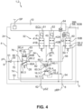
- the Fig. 3 and 4 now show a second and a third embodiment of the electropneumatic parking brake device 1 according to the first embodiment ( Fig. 1 ), which in turn is designed as a parking brake module 2 and wherein the bypass valve 50 is integrated into the parking brake module 2, namely in a common module housing 4.
- the first embodiment Fig. 1
- Identical and similar elements are provided with the same reference numerals, so that reference is made to the above description in its entirety.
- the pilot valve unit 32 differs from the pilot valve unit 32 according to the first embodiment ( Fig. 1 ).
- the other elements are identical, so reference is made to the above description for them.
- a supply pressure path 70 extends from the supply connection 6 and is divided into a supply branch 74, a control branch 76 and a compensation path 86.
- the compensation path 86 pneumatically connects the supply pressure path 70 to a parking brake control pressure line 33, which provides the parking brake control pressure pPS to the main valve unit 34.
- a compensation valve 80 is arranged in the compensation path 82.
- the compensation valve 80 is designed as a 3/2-way valve.
- the compensation valve 80 has a first compensation valve connection 80.1, which is pneumatically connected to the supply pressure path 70.
- the compensation valve 80 has a second compensation valve connection 80.2, which is pneumatically connected to the compensation path 82.
- the compensation valve 80 has a third compensation valve connection 80.3, which is pneumatically connected to a vent line 44.
- the vent line 44 is connected to a vent connection 3, which vents to the environment.
- the compensation valve 80 has a compensation valve control port 80.4, which is pneumatically connected to the second compensation valve port 80.2 via a compensation control path 83. Pneumatic self-locking is preferably implemented by means of the compensation control path 83. A pressure present at the second compensation valve port 80.2, in particular a parking brake control pressure pPS, is provided to the compensation valve control port 80.4 via the compensation control path 83.
- the first compensation valve connection 80.1 is pneumatically connected to the second compensation valve connection 80.2, and preferably the third compensation valve connection 80.3 is blocked.
- the supply pressure path 70 is thus pneumatically connected to the compensation path 82 and thus to the parking brake control pressure line 33.
- the second compensation valve connection 80.2 is pneumatically connected to the third compensation valve connection 80.3, and preferably the first compensation valve connection 80.1 is blocked.
- the compensation path 82 and thus the parking brake control pressure line 33 is pneumatically connected to the vent port 3.
- the compensation valve 80 has a first throttle 27 between the first compensation valve connection 80.1 and the second compensation valve connection 80.2.
- the first throttle 27 advantageously has a nominal diameter that is smaller than the compensation path 82 and/or the supply pressure path 70.
- the compensation valve 80 has a second throttle 28 between the second compensation valve connection 80.2 and the third compensation valve connection 80.3.
- the second throttle 28 advantageously has a nominal diameter that is smaller than the compensation path 82 and/or the vent line 44.
- the pilot valve unit 32 has in the embodiment shown here ( Fig. 3 ) a first pilot valve 41 and a second pilot valve 42, each designed as a 2/2-way solenoid valve.
- first pilot valve 41 in an open position 41A, the supply pressure pV from the supply pressure path 70 can be provided as parking brake control pressure pPS to the parking brake control pressure line 33.
- the parking brake control pressure line 33 is arranged between the first pilot valve 41 and the second pilot valve 42 and is or can be connected pneumatically to the relay valve control connection 16.4 or the shuttle valve 60.
- the parking brake control pressure pPS in the parking brake control pressure line 33 in particular at the relay valve control connection 16.4, can be captured or held for permanent actuation.
- the second pilot valve 42 is also in a blocking position 42B.
- the parking brake control unit 10 provides the first switching signal S1 to actuate the first pilot valve 41 and the second switching signal S2 to actuate the second pilot valve 42.
- the second pilot valve 42 By switching the second pilot valve 42 to an open position 42A, the parking brake control pressure line 33 for venting the relay valve control connection 16.4 can be pneumatically connected to the vent line 44.
- the parking brake control pressure line 33 is additionally—as already known from the first exemplary embodiment—pneumatically connectable to the anti-compound connection 62.
- an additional parking brake pressure pSZ can be provided to the parking brake control pressure line 33 and, in particular, to the relay valve control connection 16.4 in order to control a parking brake pressure pBP at the spring-loaded connection 8, 9 independently of the pilot valve unit 32.
- the additional parking brake pressure pSZ can be provided by a service brake function (not shown here) in order to implement an anti-compound function.
- the electropneumatic parking brake device 1 has a parking brake pressure sensor 64 which is pneumatically connected to the spring-loaded connection 8, 9 for measuring the parking brake pressure pBP.
- the third embodiment according to Fig. 4 is based on the second embodiment according to Fig. 3 .
- the only difference between the third embodiment ( Fig. 4 ) and the second embodiment ( Fig. 2 ) is that the bypass branch line 56 does not branch off from the parking brake pressure line 54, i.e., downstream of the relay valve 16, but rather between the pilot valve unit 32 and the main valve unit 34, so that the bypass valve 50 can vent or supply the parking brake control pressure pPS, depending on the switching position. This can increase air flow efficiency.
- Fig. 5 now shows a second vehicle 200, which is essentially based on the embodiment of the Fig. 1 so that identical and similar elements are provided with the same reference numerals and the differences are highlighted below.
- the vehicle has 200 according to Fig. 5 an electropneumatic parking brake device 1 in which the bypass valve 50 is arranged separately and externally to the parking brake valve unit 24.
- the parking brake valve unit 24 is integrated together with the parking brake control unit 10 into a conventional parking brake module 25.
- the parking brake module 25 has a parking brake module housing 26.
- the bypass valve 50 can be flanged to the parking brake module housing 26 or installed separately and remotely from it in the brake system 204.
- the bypass branch line 56 then branches off externally from the parking brake module 25, specifically from a spring brake pressure line 46a, 46b, which runs from the first spring brake connection 8 to the first and third spring brake cylinders 242a, 242c or from the second spring brake connection 9 to the second and fourth spring brake cylinders 242b, 242d. From which of the first and second spring brake pressure lines 46a, 46b the bypass branch line 56 branches off is functionally irrelevant and should be selected so that the smallest possible installation space is achieved. In the example shown here ( Fig. 5 ), the bypass branch line 56 branches off from the second spring brake pressure line 46b via a bypass branch node 57. Since (as in Fig.
- first and second spring-loaded brake connections 8, 9 are connected internally in the electropneumatic parking brake module 2 directly and without further intermediate circuits, it is sufficient to vent or release one of the first and second spring-loaded brake pressure lines 46a, 46b in order to vent or release all four spring-loaded brake cylinders 242a - 242d.
- Fig. 6 and 7 now show embodiments which are used in the context of the vehicle 200 according to Fig. 5 can be used and thus also include externally arranged bypass valves 50. Identical and similar elements are again provided with the same reference numerals, so that reference is made in full to the above description. In the following, the differences from the previous embodiments are particularly highlighted.
- the Fig. 6 The embodiment shown is largely based on the one in Fig. 1
- the embodiment shown and in particular the pilot valve unit 32 and the main valve unit 34 are of identical design.
- the bypass branch line 56 branches off externally from the parking brake module housing 26 and thus also downstream from the second spring-loaded brake connection 9.
- the bypass supply line 53 also runs externally to the parking brake module housing 26 and branches off from the bypass supply node 51, which is arranged upstream of the supply connection 6, i.e. between the parking brake supply 26 and the supply connection 6.
- the bypass valve 50 is therefore constructed completely parallel to the parking brake valve unit 24 and can connect the second spring-loaded brake pressure line 46b immediately and directly to the parking brake supply 26.
- the Fig. 7 The embodiment shown now differs from the one in Fig. 6 shown embodiment in that the second bypass valve connection 50.2 is not connected to the parking brake supply 26 via a bypass supply line 53, but to a vent 3. In this embodiment, it is therefore not possible to vent the spring-loaded connection 8, but only to vent it.
Landscapes
- Engineering & Computer Science (AREA)
- Transportation (AREA)
- Mechanical Engineering (AREA)
- Braking Systems And Boosters (AREA)
Claims (28)
- Dispositif de frein de stationnement électropneumatique (1) pour l'aération et la purge d'un ou de plusieurs cylindres de frein à accumulateur à ressort d'un système de freinage pneumatique (204) pouvant être commandé électroniquement pour un véhicule (200, 202), comprenantune unité de soupape de frein de stationnement (24) comportant un raccord de réserve pour recevoir une pression de réserve (pV) provenant d'une réserve de frein de stationnement (26), dans lequel l'unité de soupape de frein de stationnement (24) commande une pression de frein de stationnement (pBP) au niveau d'au moins un raccord d'accumulateur à ressort (8, 9) en fonction d'un signal de frein de stationnement (SP),et une soupape antiretour (30) disposée entre l'unité de soupape de frein de stationnement (24) et la réserve de frein de stationnement (26) pour empêcher de l'air comprimé de refluer de l'unité de soupape de frein de stationnement (24) vers la réserve de frein de stationnement (26),caractérisé par une soupape de dérivation (50) qui peut être commutée pour aérer et pour purger le raccord d'accumulateur à ressort (8, 9), dans lequel la soupape de dérivation (50) est commandée et commutée indépendamment de l'unité de soupape de frein de stationnement (24).
- Dispositif de frein de stationnement électropneumatique selon la revendication 1, dans lequel la soupape de dérivation (50) est conçue de manière à être électromagnétique et peut être commandée par une autre unité de commande électronique (40) indépendante de l'unité de soupape de frein de stationnement (24).
- Dispositif de frein de stationnement électropneumatique selon la revendication 2, présentant un capteur de pression de dérivation (52) permettant de détecter la pression de frein de stationnement (pBP) commandée au niveau du raccord d'accumulateur à ressort, dans lequel le capteur de pression de dérivation (52) est connecté à l'autre unité de commande électronique (40) indépendante de l'unité de soupape de frein de stationnement (24).
- Dispositif de frein de stationnement électropneumatique selon l'une des revendications précédentes, dans lequel la soupape de dérivation (50) est monostable et peut occuper une position de blocage (50A) ainsi qu'une position de passage (50B), dans lequel la soupape de dérivation (50) est stable dans la position de blocage (50A).
- Dispositif de frein de stationnement électropneumatique selon l'une des revendications précédentes, dans lequel la soupape de dérivation (50) présente un premier raccord de soupape de dérivation (50.1) relié au raccord d'accumulateur à ressort (8, 9) ou à une unité de soupape principale (34) montée en amont du raccord d'accumulateur à ressort (8, 9), et un second raccord de soupape de dérivation (50.2) relié à un moyen de purge (3).
- Dispositif de frein de stationnement électropneumatique selon l'une des revendications 1 à 4 précédentes, dans lequel la soupape de dérivation (50) présente un premier raccord de soupape de dérivation (50.1) relié au raccord d'accumulateur à ressort (8, 9) ou à une unité de soupape principale (34) montée en amont du raccord d'accumulateur à ressort (8, 9), et un second raccord de soupape de dérivation (50.2) relié à la réserve de frein de stationnement (26) en amont de la soupape antiretour (30).
- Dispositif de frein de stationnement électropneumatique selon l'une des revendications précédentes, dans lequel la soupape de dérivation (50) est conçue en tant qu'unité structurale avec l'unité de soupape de frein de stationnement (24).
- Dispositif de frein de stationnement électropneumatique selon l'une des revendications précédentes, dans lequel la soupape de dérivation (50) est montée avec l'unité de soupape de frein de stationnement (24) dans un boîtier modulaire (4).
- Dispositif de frein de stationnement électropneumatique selon l'une des revendications précédentes, dans lequel la soupape de dérivation (50) est directement reliée à une conduite de pression de frein de stationnement (54) raccordée au raccord d'accumulateur à ressort (8, 9) en aval de celui-ci.
- Dispositif de frein de stationnement électropneumatique selon l'une des revendications précédentes, dans lequel l'unité de soupape de frein de stationnement (24) présente une unité de soupape pilote (32) et une unité de soupape principale (34), dans lequel l'unité de soupape pilote (32) est prévue pour commander une pression de commande de frein de stationnement (pPS) au niveau de l'unité de soupape principale (34), laquelle commande ensuite la pression de frein de stationnement (pBP) au niveau du raccord d'accumulateur à ressort (8, 9) en fonction de la pression de commande de frein de stationnement (pPS) reçue.
- Dispositif de frein de stationnement électropneumatique selon la revendication 10, dans lequel la première soupape de dérivation (50) est reliée à l'unité de soupape principale (34), dans lequel la pression de commande de frein de stationnement (pPS) peut être purgée par l'intermédiaire de la soupape de dérivation (50).
- Dispositif de frein de stationnement électropneumatique selon la revendication 11, dans lequel la soupape de dérivation (50) est reliée à une conduite de dérivation (56) qui dérive à partir d'une conduite de pression de commande de frein de stationnement (33) par l'intermédiaire de laquelle la pression de commande de frein de stationnement (pPS) est fournie par l'unité de soupape pilote (32) à l'unité de soupape principale (34).
- Dispositif de frein de stationnement électropneumatique selon la revendication 12, dans lequel une première soupape de changement (60) est prévue dans la conduite de pression de commande de frein de stationnement (33), laquelle première soupape de changement présente un premier raccord de soupape de changement (60.1) relié à l'unité de soupape pilote (32), un deuxième raccord de soupape de changement (60.2) relié à un raccord de non-addition des efforts de freinage (62) et un troisième raccord de soupape de changement (60.3) relié à l'unité de soupape principale (34), dans lequel la première soupape de changement (60) commande respectivement, au niveau du troisième raccord de soupape de changement (60.3), la pression plus élevée présente au niveau du premier raccord de soupape de changement (60.1) et du deuxième raccord de soupape de changement (60.2).
- Dispositif de frein de stationnement électropneumatique selon la revendication 13, dans lequel la conduite de dérivation (56) dérive entre le premier raccord de soupape de changement (60.1) et l'unité de soupape pilote (32).
- Dispositif de frein de stationnement électropneumatique selon l'une des revendications 10 à 14 précédentes, dans lequel l'unité de soupape de frein de stationnement (24) présente une soupape de compensation (80) qui est prévue pour maintenir une pression de commande de frein de stationnement (pPS) commandée par l'unité de soupape pilote (32) au niveau de l'unité de soupape principale (34) et ainsi compenser au moins partiellement une fuite de l'unité de soupape pilote (32) et/ou de l'unité de soupape principale (34).
- Dispositif de frein de stationnement électropneumatique selon la revendication 15,dans lequel la soupape de compensation (80) est conçue en tant que soupape à 3/2 voies (81) pouvant être commandée pneumatiquement et présente un premier raccord de soupape de compensation (80.1) relié à la soupape antiretour (30), un deuxième raccord de soupape de compensation (80.2) relié à une conduite (82) conduisant la pression de commande de frein de stationnement (pPS) et un troisième raccord de soupape de compensation (80.3) relié à un moyen de purge (3),dans lequel la soupape de compensation (80) est chargée de manière élastique une première position de commutation est précontrainte dans laquelle le deuxième raccord de soupape de compensation (80.2) est relié au troisième raccord de soupape de compensation (80.3) et, si une pression de commande de soupape de compensation (pSK) fournie à un raccord de commande de soupape de compensation (80.4) dépasse une valeur seuil de soupape de compensation, commute vers une seconde position de commutation dans laquelle le premier raccord de soupape de compensation (80.1) est relié au deuxième raccord de soupape de compensation (80.2), etdans lequel la pression de commande de soupape de compensation (pSK) est une pression (pPS) appliquée ou commandée au niveau du deuxième raccord de soupape de compensation (80.2), moyennant quoi un maintien automatique pneumatique pour la soupape de compensation (80) est réalisé.
- Dispositif de frein de stationnement électropneumatique selon la revendication 16, dans lequel la soupape de compensation (80) est conçue de manière à être étranglée, de telle sorte que la liaison du premier raccord de soupape de compensation (80.1) avec le deuxième raccord de soupape de compensation (80.2) ainsi que la liaison du deuxième raccord de soupape de compensation (80.2) avec le troisième raccord de soupape de compensation (80.3) sont respectivement étranglées.
- Dispositif de frein de stationnement électropneumatique selon l'une des revendications précédentes, dans lequel l'unité de soupape de frein de stationnement (24) et la soupape de dérivation (50) sont alimentées en tension électrique par deux sources de tension (210, 212) indépendantes.
- Système de freinage pneumatique (204) pouvant être commandé électroniquement pour un véhicule (200, 202), comprenantau moins un premier actionneur de frein d'essieu avant (228a) et un second actionneur de frein d'essieu avant (228b) sur un essieu avant (VA) du véhicule (200) et au moins un premier actionneur de frein d'essieu arrière (242a) et un second actionneur de frein d'essieu arrière (242b) sur un essieu arrière (HA1, HA2) du véhicule (200) ;un système primaire (B1) comportant une unité de commande primaire (400) au moins pour la commande du premier actionneur de frein d'essieu avant (228a), du second actionneur de frein d'essieu avant (228b), du premier actionneur de frein d'essieu arrière (242a) et du second actionneur de frein d'essieu arrière (242b) ; etun dispositif de frein de stationnement électropneumatique (1) selon l'une des revendications 1 à 18, dans lequel au moins un premier cylindre de frein à accumulateur à ressort (232a) est raccordé à l'au moins un raccord d'accumulateur à ressort (8, 9) sur l'essieu arrière (HA1, HA2), et dans lequel la soupape de dérivation (50) peut être commutée pour l'aération et pour la purge du premier cylindre de frein à accumulateur à ressort (242a), dans lequel la soupape de dérivation (50) est commandée et commutée indépendamment de l'unité de soupape de frein de stationnement (24).
- Système de freinage pneumatique (1) pouvant être commandé électroniquement selon la revendication 19, dans lequel l'unité de soupape de frein de stationnement (24) est connectée à une unité de commande de frein de stationnement (10) et reçoit en provenance de celle-ci des signaux de commutation (S1, S2), et dans lequel la soupape de dérivation (50) est reliée à une autre unité de commande électronique (40) indépendante de l'unité de soupape de frein de stationnement (24) et reçoit en provenance de celle-ci au moins un signal de commutation de dérivation (SB).
- Système de freinage pneumatique (1) pouvant être commandé électroniquement selon la revendication 20, dans lequel l'unité de commande de frein de stationnement (10) est connectée à une première source de tension (212) et est alimentée en tension électrique par celle-ci, et l'autre unité de commande électronique (40) est connectée à une seconde source de tension (210) et est alimentée en tension électrique par celle-ci.
- Système de freinage pneumatique (1) pouvant être commandé électroniquement selon l'une des revendications 19 à 21 précédentes, dans lequel l'unité de commande primaire (400) forme ou présente l'autre unité de commande (40).
- Système de freinage pneumatique (1) pouvant être commandé électroniquement selon l'une des revendications 19 à 22 précédentes, présentant en outre un système secondaire (B2) comportant une unité de commande secondaire (404) au moins pour la commande du premier actionneur de frein d'essieu avant (20a), du second actionneur de frein d'essieu avant (20b), du premier actionneur de frein d'essieu arrière (18a) et du second actionneur de frein d'essieu arrière (18b), dans lequel, dans le cas où une erreur (F) est déterminée dans le système primaire (6), la commande du système de freinage pneumatique (1) pouvant être commandé électroniquement est effectuée au moins partiellement par le système secondaire (8).
- Système de freinage pneumatique pouvant être commandé électroniquement selon la revendication 23, dans lequel l'unité de commande secondaire (40) forme ou présente l'autre unité de commande.
- Véhicule (2), en particulier véhicule utilitaire (200), comportant un essieu avant (VA), au moins un premier essieu arrière (HA1) et un système de freinage pneumatique (1) pouvant être commandé électroniquement selon l'une des revendications 19 à 24 précédentes.
- Procédé pour la commande d'un système de freinage pneumatique pouvant être commandé électroniquement, de préférence selon l'une des revendications 19 à 24, comportant les étapes consistant à :- commander une unité de soupape de frein de stationnement au moyen d'une unité de commande de frein de stationnement (10) pour l'aération et la purge d'au moins un cylindre de frein à accumulateur à ressort (19a) sur un essieu arrière (HA1, HA2) d'un véhicule utilitaire, dans lequel l'unité de soupape de frein de stationnement est reliée à une réserve de frein de stationnement par l'intermédiaire d'une soupape antiretour et reçoit en provenance de celle-ci une pression de réserve ;- déterminer un défaut dans le système de freinage pneumatique pouvant être commandé électroniquement, en particulier l'unité de commande de frein de stationnement (10) ou l'unité de soupape de frein de stationnement ;- commuter une soupape de dérivation qui est reliée à la fois à l'au moins un cylindre de frein à accumulateur à ressort et à la réserve de frein de stationnement, dans une position de purge pour purger l'au moins un cylindre de frein à accumulateur à ressort ;dans lequel la soupape de dérivation commute en réponse à un signal de commutation de dérivation qui est fourni par une autre unité de commande électronique qui est indépendante de l'unité de commande de frein de stationnement (10).
- Procédé selon la revendication 26, dans lequel l'unité de commande de frein de stationnement (10) est connectée à une première source de tension et est alimentée en tension électrique par celle-ci, et l'autre unité de commande est connectée à une seconde source de tension et est alimentée en tension électrique par celle-ci.
- Procédé selon la revendication 26 ou 27, comprenant l'étape consistant à :- abaisser la pression de réserve dans la réserve de frein de stationnement pour purger l'au moins un cylindre de frein à accumulateur à ressort.
Applications Claiming Priority (2)
| Application Number | Priority Date | Filing Date | Title |
|---|---|---|---|
| DE102021122498.5A DE102021122498A1 (de) | 2021-08-31 | 2021-08-31 | Betriebssichere Parkbremsventileinheit mit einem Bypassventil |
| PCT/EP2022/073022 WO2023030898A1 (fr) | 2021-08-31 | 2022-08-18 | Unité de valve de frein de stationnement fiable dotée d'une soupape de dérivation |
Publications (2)
| Publication Number | Publication Date |
|---|---|
| EP4396052A1 EP4396052A1 (fr) | 2024-07-10 |
| EP4396052B1 true EP4396052B1 (fr) | 2025-03-26 |
Family
ID=83232528
Family Applications (1)
| Application Number | Title | Priority Date | Filing Date |
|---|---|---|---|
| EP22765853.1A Active EP4396052B1 (fr) | 2021-08-31 | 2022-08-18 | Unité de soupape de frein de stationnement fiable avec une soupape de dérivation |
Country Status (5)
| Country | Link |
|---|---|
| US (2) | US12263821B2 (fr) |
| EP (1) | EP4396052B1 (fr) |
| CN (1) | CN117677549A (fr) |
| DE (1) | DE102021122498A1 (fr) |
| WO (1) | WO2023030898A1 (fr) |
Families Citing this family (11)
| Publication number | Priority date | Publication date | Assignee | Title |
|---|---|---|---|---|
| WO2021104939A1 (fr) * | 2019-11-26 | 2021-06-03 | Zf Cv Systems Global Gmbh | Procédé de fonctionnement d'un module de frein de stationnement électropneumatique, module de frein de stationnement électropneumatique, système de freinage pneumatique à commande électronique, et véhicule |
| US20230373456A1 (en) * | 2020-10-14 | 2023-11-23 | Zf Cv Systems Europe Bv | Brake pressure modulator and use of a brake pressure modulator |
| US12589722B2 (en) * | 2023-11-15 | 2026-03-31 | Bendix Commercial Vehicle Systems Llc | Service brake control system for a combination vehicle |
| DE102023134554A1 (de) * | 2023-12-11 | 2025-06-12 | Zf Cv Systems Global Gmbh | Ausfallsichere Bypassventilanordnung und Bremssystem umfassend eine ausfallsichere Bypassventilanordnung |
| DE102023136453A1 (de) | 2023-12-22 | 2025-06-26 | Zf Cv Systems Global Gmbh | Elektropneumatische Feststellbremseinrichtung mit parallelen Entlüftungspfaden |
| DE102023136455A1 (de) * | 2023-12-22 | 2025-06-26 | Zf Cv Systems Global Gmbh | Elektropneumatische Feststellbremseinrichtung mit Feststellbremsredundanzeinheit |
| DE102023136451A1 (de) * | 2023-12-22 | 2025-06-26 | Zf Cv Systems Global Gmbh | Betriebsbremsentlüftungseinheit für eine betriebssichere Feststellbremsanordnung |
| DE102023136452A1 (de) * | 2023-12-22 | 2025-06-26 | Zf Cv Systems Global Gmbh | Anordnung zur Druckluftversorgung eines pneumatischen Bremssystems und Verfahren zum Einlegen einer Feststellbremse durch Begrenzung der Fördermenge |
| DE102023136454A1 (de) * | 2023-12-22 | 2025-06-26 | Zf Cv Systems Global Gmbh | Elektronisch steuerbares pneumatisches Bremssystem mit einem Umkehrrelaisventil zum Be- und Entlüften eines Federspeicherbremszylinders eines Fahrzeugs |
| DE102023136456A1 (de) * | 2023-12-22 | 2025-06-26 | Zf Cv Systems Global Gmbh | Elektropneumatische Feststellbremseinrichtung mit Notbremsfunktion |
| US20260014968A1 (en) * | 2024-07-12 | 2026-01-15 | Bendix Commercial Vehicle Systems Llc | Trailer brake control apparatus for a vehicle train and methods therefor |
Family Cites Families (16)
| Publication number | Priority date | Publication date | Assignee | Title |
|---|---|---|---|---|
| DE10336611A1 (de) | 2003-08-08 | 2005-03-03 | Wabco Gmbh & Co.Ohg | Druckmittelbetriebene Bremsanlage für ein Fahrzeug |
| DE102007047691A1 (de) * | 2007-10-05 | 2009-04-09 | Wabco Gmbh | Elektropneumatischer Feststellbremsmodulator zur Steuerung einer Feststellbremsfunktion von Bremsen eines Anhängefahrzeugs in einem Fahrzeugzug |
| DE102008007877B3 (de) | 2008-02-06 | 2009-11-26 | Knorr-Bremse Systeme für Nutzfahrzeuge GmbH | Parkbremseinrichtung |
| DE102008027731B4 (de) * | 2008-06-11 | 2015-06-25 | Knorr-Bremse Systeme für Nutzfahrzeuge GmbH | Elektrische Feststellbremse mit Einfallsperre und Verfahren zum Betreiben einer elektrischen Feststellbremse mit Einfallsperre |
| DE102009037636A1 (de) | 2009-08-14 | 2011-02-17 | Knorr-Bremse Systeme für Nutzfahrzeuge GmbH | Steuergerät und Verfahren zum Testen einer Ventileinrichtung einer elektrischen Feststellbremse |
| DE102015008377A1 (de) | 2015-06-29 | 2016-12-29 | Wabco Gmbh | Feststellbremsmodul, Bremsanlage mit einem derartigen Feststellbremsmodul, Fahrzeug damit sowie Verfahren zum Betreiben einer Feststellbremseinrichtung |
| DE102016005318A1 (de) * | 2016-05-02 | 2017-11-02 | Wabco Gmbh | Elektronisch steuerbares pneumatisches Bremssystem in einem Nutzfahrzeug sowie Verfahren zum elektronischen Steuern eines pneumatischen Bremssystems. |
| DE102016010460A1 (de) * | 2016-08-31 | 2018-03-01 | Wabco Gmbh | Elektronisch steuerbares pneumatisches Bremssystem in einem Nutzfahrzeug sowie Verfahren zum elektronischen Steuern eines pneumatischen Bremssystems in einem Nutzfahrzeug |
| DE102017005980A1 (de) * | 2017-03-21 | 2018-09-27 | Wabco Gmbh | Integriertes Anhängersteuermodul (TCV) mit externer elektropneumatischer Handbremseinheit (EPH) |
| DE102017005757A1 (de) | 2017-06-19 | 2018-12-20 | Wabco Gmbh | Notlöseventil und Feststellbremsmodul einer Druckluftbremsanlage |
| DE102017007780A1 (de) * | 2017-08-16 | 2019-02-21 | Wabco Gmbh | Elektropneumatisches Festellbremsmodul mit direkt gesteuerten Ventilen |
| DE102017009307A1 (de) * | 2017-10-07 | 2019-04-11 | Wabco Gmbh | Parkbrems-Ventileinrichtung |
| DE102018117596A1 (de) * | 2018-07-20 | 2020-01-23 | Wabco Gmbh | Elektropneumatisches Feststellbremsmodul mit direkt gesteuerten Ventilen und Anti-Compound-Anschluss |
| DE102019131110A1 (de) | 2019-11-18 | 2021-05-20 | Wabco Europe Bvba | Bremssystem mit sicherer Notstoppfunktion und Verfahren hierzu |
| WO2021104939A1 (fr) * | 2019-11-26 | 2021-06-03 | Zf Cv Systems Global Gmbh | Procédé de fonctionnement d'un module de frein de stationnement électropneumatique, module de frein de stationnement électropneumatique, système de freinage pneumatique à commande électronique, et véhicule |
| DE102019133010A1 (de) | 2019-12-04 | 2021-06-10 | Zf Cv Systems Global Gmbh | Ausfallsicherheitsventileinheit für eine Parkbremsfunktion sowie Parkbremsventilanordnung |
-
2021
- 2021-08-31 DE DE102021122498.5A patent/DE102021122498A1/de active Pending
-
2022
- 2022-08-18 WO PCT/EP2022/073022 patent/WO2023030898A1/fr not_active Ceased
- 2022-08-18 EP EP22765853.1A patent/EP4396052B1/fr active Active
- 2022-08-18 CN CN202280050728.8A patent/CN117677549A/zh active Pending
-
2024
- 2024-02-27 US US18/589,106 patent/US12263821B2/en active Active
-
2025
- 2025-02-21 US US19/060,390 patent/US20250187576A1/en active Pending
Also Published As
| Publication number | Publication date |
|---|---|
| CN117677549A (zh) | 2024-03-08 |
| US20250187576A1 (en) | 2025-06-12 |
| US12263821B2 (en) | 2025-04-01 |
| DE102021122498A1 (de) | 2023-03-02 |
| WO2023030898A1 (fr) | 2023-03-09 |
| EP4396052A1 (fr) | 2024-07-10 |
| US20240198991A1 (en) | 2024-06-20 |
Similar Documents
| Publication | Publication Date | Title |
|---|---|---|
| EP4396052B1 (fr) | Unité de soupape de frein de stationnement fiable avec une soupape de dérivation | |
| EP4061678B1 (fr) | Système de frein doté d'une fonction d'arrêt d'urgence plus sûr et procédé associé | |
| EP4058334B1 (fr) | Module de commande électropneumatique | |
| EP3600981B1 (fr) | Frein à main électro-pneumatique (eph) avec valve tcv (système de commande européen et scandinave) intégrée | |
| EP3774465B1 (fr) | Module de contrôle électro-pneumatique de frein pourvue d'une ligne redondante d'alimentation en pression | |
| EP3600996B1 (fr) | Module integre pour remorque avec unité externe de freinage de stationnement electro-pneumatique | |
| EP3755589B1 (fr) | Équipement électropneumatique d'un véhicule | |
| EP3145769B1 (fr) | Moyen de commande de freinage électropneumatique avec purge automatique du frein à accumulation en cas de panne de courant | |
| EP4069559B1 (fr) | Ensemble soupape de frein de stationnement monostable et insensible aux défaillances | |
| EP3823868B1 (fr) | Module de frein de stationnement électropneumatique pourvu de soupapes à commande directe et d'un raccord de non-addition des efforts de freinage | |
| EP3829946B1 (fr) | Frein à main électropneumatique (ebh) avec tcv partiellement decouplé (type d'activation européen) | |
| EP4069560B1 (fr) | Soupape fail-safe pour frein de stationnement et agencement de ventil d'un frein de stationnement | |
| DE102021131327A1 (de) | Ausfallsicheres redundantes Bremssystem mit Druckeinspeisung über einen Entlüftungspfad des primären Modulators | |
| EP4366994B1 (fr) | Ensemble soupape électropneumatique doté d'une soupape de sécurité à verrouillage automatique | |
| WO2023030797A1 (fr) | Système de freinage pneumatique à commande électronique avec application de freinage à sécurité intégrée pour conduite autonome, comprenant uniquement une soupape navette | |
| DE102023136451A1 (de) | Betriebsbremsentlüftungseinheit für eine betriebssichere Feststellbremsanordnung | |
| EP3112231A1 (fr) | Module de frein de stationnement, installation de freinage et vehicule ainsi equipe et procede de fonctionnement d'un dispositif de frein de stationnement avec un tel module | |
| EP4341136B1 (fr) | Unité structurale électropneumatique à ensemble soupape de sécurité intégré pour des défaillances multiples, système de freinage pneumatique à commande électronique, ainsi que procédé pour faire fonctionner un système de freinage | |
| EP4237298A1 (fr) | Dispositif électropneumatique pourvu d'une unité de valve de protection | |
| DE102014116732A1 (de) | Bremseinrichtung eines Fahrzeugs mit elektrischer und durch eine pneumatische Notzuspanneinrichtung zuspannbarer Feststellbremse | |
| DE102023136454A1 (de) | Elektronisch steuerbares pneumatisches Bremssystem mit einem Umkehrrelaisventil zum Be- und Entlüften eines Federspeicherbremszylinders eines Fahrzeugs |
Legal Events
| Date | Code | Title | Description |
|---|---|---|---|
| STAA | Information on the status of an ep patent application or granted ep patent |
Free format text: STATUS: UNKNOWN |
|
| STAA | Information on the status of an ep patent application or granted ep patent |
Free format text: STATUS: THE INTERNATIONAL PUBLICATION HAS BEEN MADE |
|
| PUAI | Public reference made under article 153(3) epc to a published international application that has entered the european phase |
Free format text: ORIGINAL CODE: 0009012 |
|
| STAA | Information on the status of an ep patent application or granted ep patent |
Free format text: STATUS: REQUEST FOR EXAMINATION WAS MADE |
|
| 17P | Request for examination filed |
Effective date: 20231212 |
|
| AK | Designated contracting states |
Kind code of ref document: A1 Designated state(s): AL AT BE BG CH CY CZ DE DK EE ES FI FR GB GR HR HU IE IS IT LI LT LU LV MC MK MT NL NO PL PT RO RS SE SI SK SM TR |
|
| DAV | Request for validation of the european patent (deleted) | ||
| DAX | Request for extension of the european patent (deleted) | ||
| GRAP | Despatch of communication of intention to grant a patent |
Free format text: ORIGINAL CODE: EPIDOSNIGR1 |
|
| STAA | Information on the status of an ep patent application or granted ep patent |
Free format text: STATUS: GRANT OF PATENT IS INTENDED |
|
| GRAS | Grant fee paid |
Free format text: ORIGINAL CODE: EPIDOSNIGR3 |
|
| GRAA | (expected) grant |
Free format text: ORIGINAL CODE: 0009210 |
|
| STAA | Information on the status of an ep patent application or granted ep patent |
Free format text: STATUS: THE PATENT HAS BEEN GRANTED |
|
| INTG | Intention to grant announced |
Effective date: 20250123 |
|
| AK | Designated contracting states |
Kind code of ref document: B1 Designated state(s): AL AT BE BG CH CY CZ DE DK EE ES FI FR GB GR HR HU IE IS IT LI LT LU LV MC MK MT NL NO PL PT RO RS SE SI SK SM TR |
|
| REG | Reference to a national code |
Ref country code: GB Ref legal event code: FG4D Free format text: NOT ENGLISH |
|
| REG | Reference to a national code |
Ref country code: CH Ref legal event code: EP |
|
| REG | Reference to a national code |
Ref country code: DE Ref legal event code: R096 Ref document number: 502022003359 Country of ref document: DE |
|
| REG | Reference to a national code |
Ref country code: IE Ref legal event code: FG4D Free format text: LANGUAGE OF EP DOCUMENT: GERMAN |
|
| PG25 | Lapsed in a contracting state [announced via postgrant information from national office to epo] |
Ref country code: RS Free format text: LAPSE BECAUSE OF FAILURE TO SUBMIT A TRANSLATION OF THE DESCRIPTION OR TO PAY THE FEE WITHIN THE PRESCRIBED TIME-LIMIT Effective date: 20250626 |
|
| PG25 | Lapsed in a contracting state [announced via postgrant information from national office to epo] |
Ref country code: FI Free format text: LAPSE BECAUSE OF FAILURE TO SUBMIT A TRANSLATION OF THE DESCRIPTION OR TO PAY THE FEE WITHIN THE PRESCRIBED TIME-LIMIT Effective date: 20250326 |
|
| REG | Reference to a national code |
Ref country code: LT Ref legal event code: MG9D |
|
| PG25 | Lapsed in a contracting state [announced via postgrant information from national office to epo] |
Ref country code: NO Free format text: LAPSE BECAUSE OF FAILURE TO SUBMIT A TRANSLATION OF THE DESCRIPTION OR TO PAY THE FEE WITHIN THE PRESCRIBED TIME-LIMIT Effective date: 20250626 |
|
| PG25 | Lapsed in a contracting state [announced via postgrant information from national office to epo] |
Ref country code: HR Free format text: LAPSE BECAUSE OF FAILURE TO SUBMIT A TRANSLATION OF THE DESCRIPTION OR TO PAY THE FEE WITHIN THE PRESCRIBED TIME-LIMIT Effective date: 20250326 |
|
| PG25 | Lapsed in a contracting state [announced via postgrant information from national office to epo] |
Ref country code: LV Free format text: LAPSE BECAUSE OF FAILURE TO SUBMIT A TRANSLATION OF THE DESCRIPTION OR TO PAY THE FEE WITHIN THE PRESCRIBED TIME-LIMIT Effective date: 20250326 |
|
| PGFP | Annual fee paid to national office [announced via postgrant information from national office to epo] |
Ref country code: FR Payment date: 20250610 Year of fee payment: 4 |
|
| PG25 | Lapsed in a contracting state [announced via postgrant information from national office to epo] |
Ref country code: BG Free format text: LAPSE BECAUSE OF FAILURE TO SUBMIT A TRANSLATION OF THE DESCRIPTION OR TO PAY THE FEE WITHIN THE PRESCRIBED TIME-LIMIT Effective date: 20250326 Ref country code: GR Free format text: LAPSE BECAUSE OF FAILURE TO SUBMIT A TRANSLATION OF THE DESCRIPTION OR TO PAY THE FEE WITHIN THE PRESCRIBED TIME-LIMIT Effective date: 20250627 |
|
| REG | Reference to a national code |
Ref country code: NL Ref legal event code: MP Effective date: 20250326 |
|
| PG25 | Lapsed in a contracting state [announced via postgrant information from national office to epo] |
Ref country code: NL Free format text: LAPSE BECAUSE OF FAILURE TO SUBMIT A TRANSLATION OF THE DESCRIPTION OR TO PAY THE FEE WITHIN THE PRESCRIBED TIME-LIMIT Effective date: 20250326 |
|
| PG25 | Lapsed in a contracting state [announced via postgrant information from national office to epo] |
Ref country code: SE Free format text: LAPSE BECAUSE OF FAILURE TO SUBMIT A TRANSLATION OF THE DESCRIPTION OR TO PAY THE FEE WITHIN THE PRESCRIBED TIME-LIMIT Effective date: 20250326 |
|
| PG25 | Lapsed in a contracting state [announced via postgrant information from national office to epo] |
Ref country code: SM Free format text: LAPSE BECAUSE OF FAILURE TO SUBMIT A TRANSLATION OF THE DESCRIPTION OR TO PAY THE FEE WITHIN THE PRESCRIBED TIME-LIMIT Effective date: 20250326 |
|
| PG25 | Lapsed in a contracting state [announced via postgrant information from national office to epo] |
Ref country code: ES Free format text: LAPSE BECAUSE OF FAILURE TO SUBMIT A TRANSLATION OF THE DESCRIPTION OR TO PAY THE FEE WITHIN THE PRESCRIBED TIME-LIMIT Effective date: 20250326 Ref country code: PT Free format text: LAPSE BECAUSE OF FAILURE TO SUBMIT A TRANSLATION OF THE DESCRIPTION OR TO PAY THE FEE WITHIN THE PRESCRIBED TIME-LIMIT Effective date: 20250728 |
|
| PGFP | Annual fee paid to national office [announced via postgrant information from national office to epo] |
Ref country code: DE Payment date: 20250624 Year of fee payment: 4 |
|
| PG25 | Lapsed in a contracting state [announced via postgrant information from national office to epo] |
Ref country code: IT Free format text: LAPSE BECAUSE OF FAILURE TO SUBMIT A TRANSLATION OF THE DESCRIPTION OR TO PAY THE FEE WITHIN THE PRESCRIBED TIME-LIMIT Effective date: 20250326 Ref country code: PL Free format text: LAPSE BECAUSE OF FAILURE TO SUBMIT A TRANSLATION OF THE DESCRIPTION OR TO PAY THE FEE WITHIN THE PRESCRIBED TIME-LIMIT Effective date: 20250326 |
|
| PGFP | Annual fee paid to national office [announced via postgrant information from national office to epo] |
Ref country code: AT Payment date: 20251020 Year of fee payment: 4 |
|
| PG25 | Lapsed in a contracting state [announced via postgrant information from national office to epo] |
Ref country code: EE Free format text: LAPSE BECAUSE OF FAILURE TO SUBMIT A TRANSLATION OF THE DESCRIPTION OR TO PAY THE FEE WITHIN THE PRESCRIBED TIME-LIMIT Effective date: 20250326 |
|
| PG25 | Lapsed in a contracting state [announced via postgrant information from national office to epo] |
Ref country code: RO Free format text: LAPSE BECAUSE OF FAILURE TO SUBMIT A TRANSLATION OF THE DESCRIPTION OR TO PAY THE FEE WITHIN THE PRESCRIBED TIME-LIMIT Effective date: 20250326 |
|
| PG25 | Lapsed in a contracting state [announced via postgrant information from national office to epo] |
Ref country code: SK Free format text: LAPSE BECAUSE OF FAILURE TO SUBMIT A TRANSLATION OF THE DESCRIPTION OR TO PAY THE FEE WITHIN THE PRESCRIBED TIME-LIMIT Effective date: 20250326 |
|
| PG25 | Lapsed in a contracting state [announced via postgrant information from national office to epo] |
Ref country code: IS Free format text: LAPSE BECAUSE OF FAILURE TO SUBMIT A TRANSLATION OF THE DESCRIPTION OR TO PAY THE FEE WITHIN THE PRESCRIBED TIME-LIMIT Effective date: 20250726 |
|
| REG | Reference to a national code |
Ref country code: DE Ref legal event code: R097 Ref document number: 502022003359 Country of ref document: DE |
|
| PG25 | Lapsed in a contracting state [announced via postgrant information from national office to epo] |
Ref country code: DK Free format text: LAPSE BECAUSE OF FAILURE TO SUBMIT A TRANSLATION OF THE DESCRIPTION OR TO PAY THE FEE WITHIN THE PRESCRIBED TIME-LIMIT Effective date: 20250326 |
|
| PG25 | Lapsed in a contracting state [announced via postgrant information from national office to epo] |
Ref country code: CZ Free format text: LAPSE BECAUSE OF FAILURE TO SUBMIT A TRANSLATION OF THE DESCRIPTION OR TO PAY THE FEE WITHIN THE PRESCRIBED TIME-LIMIT Effective date: 20250326 |
|
| PLBE | No opposition filed within time limit |
Free format text: ORIGINAL CODE: 0009261 |
|
| STAA | Information on the status of an ep patent application or granted ep patent |
Free format text: STATUS: NO OPPOSITION FILED WITHIN TIME LIMIT |
|
| REG | Reference to a national code |
Ref country code: CH Ref legal event code: L10 Free format text: ST27 STATUS EVENT CODE: U-0-0-L10-L00 (AS PROVIDED BY THE NATIONAL OFFICE) Effective date: 20260211 |
|
| 26N | No opposition filed |
Effective date: 20260105 |
|
| REG | Reference to a national code |
Ref country code: CH Ref legal event code: H13 Free format text: ST27 STATUS EVENT CODE: U-0-0-H10-H13 (AS PROVIDED BY THE NATIONAL OFFICE) Effective date: 20260324 |
|
| PG25 | Lapsed in a contracting state [announced via postgrant information from national office to epo] |
Ref country code: MC Free format text: LAPSE BECAUSE OF FAILURE TO SUBMIT A TRANSLATION OF THE DESCRIPTION OR TO PAY THE FEE WITHIN THE PRESCRIBED TIME-LIMIT Effective date: 20250326 |
|
| PG25 | Lapsed in a contracting state [announced via postgrant information from national office to epo] |
Ref country code: LU Free format text: LAPSE BECAUSE OF NON-PAYMENT OF DUE FEES Effective date: 20250818 |