EP4396077B1 - System zur steuerung der blattverstellung eines propellers für ein flugzeugturbinentriebwerk - Google Patents
System zur steuerung der blattverstellung eines propellers für ein flugzeugturbinentriebwerk Download PDFInfo
- Publication number
- EP4396077B1 EP4396077B1 EP21790227.9A EP21790227A EP4396077B1 EP 4396077 B1 EP4396077 B1 EP 4396077B1 EP 21790227 A EP21790227 A EP 21790227A EP 4396077 B1 EP4396077 B1 EP 4396077B1
- Authority
- EP
- European Patent Office
- Prior art keywords
- ring
- axis
- abutments
- hub
- root
- Prior art date
- Legal status (The legal status is an assumption and is not a legal conclusion. Google has not performed a legal analysis and makes no representation as to the accuracy of the status listed.)
- Active
Links
Images


Classifications
-
- F—MECHANICAL ENGINEERING; LIGHTING; HEATING; WEAPONS; BLASTING
- F01—MACHINES OR ENGINES IN GENERAL; ENGINE PLANTS IN GENERAL; STEAM ENGINES
- F01D—NON-POSITIVE DISPLACEMENT MACHINES OR ENGINES, e.g. STEAM TURBINES
- F01D17/00—Regulating or controlling by varying flow
- F01D17/10—Final actuators
-
- B—PERFORMING OPERATIONS; TRANSPORTING
- B64—AIRCRAFT; AVIATION; COSMONAUTICS
- B64C—AEROPLANES; HELICOPTERS
- B64C11/00—Propellers, e.g. of ducted type; Features common to propellers and rotors for rotorcraft
- B64C11/02—Hub construction
- B64C11/04—Blade mountings
- B64C11/06—Blade mountings for variable-pitch blades
-
- B—PERFORMING OPERATIONS; TRANSPORTING
- B64—AIRCRAFT; AVIATION; COSMONAUTICS
- B64C—AEROPLANES; HELICOPTERS
- B64C11/00—Propellers, e.g. of ducted type; Features common to propellers and rotors for rotorcraft
- B64C11/30—Blade pitch-changing mechanisms
-
- F—MECHANICAL ENGINEERING; LIGHTING; HEATING; WEAPONS; BLASTING
- F01—MACHINES OR ENGINES IN GENERAL; ENGINE PLANTS IN GENERAL; STEAM ENGINES
- F01D—NON-POSITIVE DISPLACEMENT MACHINES OR ENGINES, e.g. STEAM TURBINES
- F01D25/00—Component parts, details, or accessories, not provided for in, or of interest apart from, other groups
- F01D25/28—Supporting or mounting arrangements, e.g. for turbine casing
-
- F—MECHANICAL ENGINEERING; LIGHTING; HEATING; WEAPONS; BLASTING
- F04—POSITIVE - DISPLACEMENT MACHINES FOR LIQUIDS; PUMPS FOR LIQUIDS OR ELASTIC FLUIDS
- F04D—NON-POSITIVE-DISPLACEMENT PUMPS
- F04D29/00—Details, component parts, or accessories
- F04D29/26—Rotors specially for elastic fluids
- F04D29/32—Rotors specially for elastic fluids for axial flow pumps
- F04D29/321—Rotors specially for elastic fluids for axial flow pumps for axial flow compressors
- F04D29/322—Blade mountings
- F04D29/323—Blade mountings adjustable
-
- F—MECHANICAL ENGINEERING; LIGHTING; HEATING; WEAPONS; BLASTING
- F05—INDEXING SCHEMES RELATING TO ENGINES OR PUMPS IN VARIOUS SUBCLASSES OF CLASSES F01-F04
- F05D—INDEXING SCHEME FOR ASPECTS RELATING TO NON-POSITIVE-DISPLACEMENT MACHINES OR ENGINES, GAS-TURBINES OR JET-PROPULSION PLANTS
- F05D2230/00—Manufacture
- F05D2230/60—Assembly methods
-
- F—MECHANICAL ENGINEERING; LIGHTING; HEATING; WEAPONS; BLASTING
- F05—INDEXING SCHEMES RELATING TO ENGINES OR PUMPS IN VARIOUS SUBCLASSES OF CLASSES F01-F04
- F05D—INDEXING SCHEME FOR ASPECTS RELATING TO NON-POSITIVE-DISPLACEMENT MACHINES OR ENGINES, GAS-TURBINES OR JET-PROPULSION PLANTS
- F05D2260/00—Function
- F05D2260/30—Retaining components in desired mutual position
- F05D2260/31—Retaining bolts or nuts
Definitions
- the present invention relates to the field of aircraft turbomachines and in particular to the propulsion propellers of these turbomachines which comprise variable-pitch blades.
- the state of the art includes in particular the documents FR-A1-3 017 163 , FR-A1-3 080 322 , WO-A1-2020/169896 , FR-A1-2 942 454 And WO-A1-2010/116080 .
- the document WO 2020/169896 A1 discloses according to its abstract an adjustable orientation blade pivot, comprising a stud having retaining means and coupling means, an internal ring, a tightening nut, a timing transmission ring positioned inside the inner radial end of the stud and provided with coupling means cooperating with the coupling means of the stud, and means for locking the timing transmission ring on the stud.
- An aircraft turbomachine propeller can be shrouded, as is the case with a fan for example, or unshrouded as is the case with an open-rotor type architecture for example.
- a propeller comprises blades that can be variable pitch.
- the turbomachine then includes a mechanism for modifying the pitch angle of the blades in order to adapt the thrust generated by the propeller according to the different phases of flight.
- the design of a propeller blade involves several disciplines whose objectives are generally antagonistic. It must allow optimal aerodynamic performance (i.e. provide thrust while maximizing efficiency), guarantee mechanical strength of the blade (i.e. withstand the mechanical constraints resulting from static and dynamic loads) while limiting the mass as well as the acoustic signature.
- the improvement of the aerodynamic performance of the propeller tends towards an increase in the BPR ( By Pass Ratio ), which results in an increase in its external diameter and therefore in the span of the blades.
- BPR By Pass Ratio
- FPR Fan Pressure Ratio
- the bowl in which the blade root is mounted, which is configured to be moved in rotation around the wedging axis and which drives the blade in this movement.
- the blade root is secured in rotation with the bowl, which thus forms a pivot connection for the blade.
- the wedging system comprises a ring, stops and a nut and this assembly allows several functions to be performed. It allows the blade root to be mounted and removed in the bowl without having to dismantle the bowl. This mounting and dismantling can be carried out from the outside, which, in the case of an unducted propeller, can allow the blade to be dismantled and removed without the need to remove the turbomachine, which may remain attached to an aircraft wing, for example.
- the stops provide a failsafe safety function. In the case, for example, where one of these stops is split or broken, the other stops would retain the blade root until the damaged stop is replaced.
- tightening the nut allows a radial preload to be applied to the blade root, which ensures that the blade is immobilized and retained. This preload is advantageously predetermined so as not to be totally compensated by the forces induced by the centrifugal forces, the aerodynamic forces and the moments applied to the blade, during the operation and rotation of the propeller.
- the guide bearings ensure the absorption of mechanical actions resulting from aerodynamic and centrifugal forces applied to the blade during operation.
- the lower bearing can be configured to ensure retention of the blade in the centrifugal force and the upper bearing can be configured to ensure absorption of bending moments resulting from aerodynamic and centrifugal forces.
- the distance between the bearings, along the pitch axis, generates a sufficient lever arm to prevent the blade from rotating, whatever the phase of flight.
- the present invention also relates to a turbomachine, in particular for an aircraft, comprising at least one system as described above.
- the ring is moved by one circumferential step at each of steps c2) and c4), this circumferential step being equal to 360°/k, k being the number of slots in the intermediate wall of the ring.
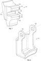
- FIG. 1 shows a blade 10 for a propeller of an aircraft turbomachine, this propeller being shrouded or unshrouded.
- the blade 10 comprises a blade 12 connected to a foot 14.
- the blade 12 has an aerodynamic profile and comprises a lower surface 12a and an upper surface 12b which are connected by an upstream leading edge 12c and by a downstream trailing edge 12d, the terms upstream and downstream referring to the flow of gases around the blade in operation.
- the blade 12 has an upper end which is free, called the apex, and a lower end which is connected to the foot 14.
- the blade 10 is made of composite material by an injection process called the RTM process (acronym for Resin Transfer Molding ).
- This process consists of preparing a fiber preform 18 by three-dimensional weaving and then placing this preform in a mold and injecting a polymerizable resin such as an epoxy resin, which will impregnate the preform.
- a polymerizable resin such as an epoxy resin
- the blade 10 here comprises a spar 22 which comprises a part forming a core of the blade 12 and which is intended to be inserted into the preform 18 before the injection of resin, and a part which extends on the side opposite the top of the blade 14 to form a part of the root 14, called body 24.
- the spar 22 is preferably made of an epoxy organic matrix composite material reinforced with 3D woven carbon fibers with the warp direction predominantly oriented radially and the weft predominantly oriented along the blade chord at the aerodynamic vein height.
- the spar may also be a more mechanically advantageous assembly of different organic matrix composite materials (thermosetting, thermoplastic or elastomer) reinforced with long fibers (carbon, glass, aramid, polypropylene) in several fiber arrangements (woven, braided, knitted, unidirectional).
- the blade 12 may be hollow or solid and includes an internal cavity filled with a foam or honeycomb type filler material. This filler material is installed around the spar 22 and is covered with a skin of organic matrix composite material to increase the blade's impact resistance.
- the shield 20 may be titanium or titanium alloy, stainless steel, steel, aluminum, nickel, etc.
- the intrados 12a or even the extrados 12b of the blade 12 may be covered with a polyurethane film for protection against erosion.
- A the axis of elongation of the blade 10 and of the blade 12 and in particular the axis of setting of the blade 10, that is to say the axis around which the angular position of the blade is adjusted. It is generally also a radial axis which therefore extends along a radius relative to the axis of rotation of the propeller equipped with this blade.
- the free end 28 has a generally parallelepiped shape in the example shown. This end 28 is preferably off-center or offset relative to the axis A to provide keying or indexing, as will be explained in more detail below.
- the bulb 32 has a generally swollen or domed shape, this bulge or doming extending all around the axis A.
- the bulb 32 has two peripheral bearing surfaces, respectively lower 32a and upper 32b, which extend around the axis A.
- the lower bearing surface 32a is oriented downwards (i.e. on the side opposite the blade 12) and radially outwards relative to the axis A
- the upper bearing surface 32b is oriented upwards (i.e. on the side of the blade 12) and radially outwards relative to the axis A.
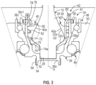
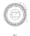
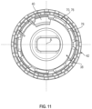
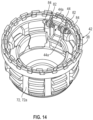
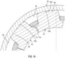
- THE figures 3 to 16 illustrate a first embodiment of a system 34 according to the invention for angular setting of a blade 10 as illustrated in Figures 1 and 2 .
- the system 34 essentially comprises a bowl 36, a ring 38, stops 40 and a nut 42.
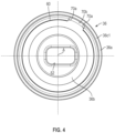
- Bowl 36 is represented alone in the figures 4 And 5 .
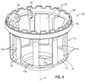
- Ring 38 is shown alone in the Figure 6 .
- the stops 40 are preferably identical and one of these stops 40 is shown in the Figure 7 .
- Nut 42 is visible at figures 3 And 9 to 14 notably.
- the bearings 46, 48 are mounted around the bowl 36, between the bowl 36 and a casing 50 of the turbomachine which may be a hub of the propeller.
- the bearings 46, 48 are here two in number and are respectively a lower bearing 46 and an upper bearing 48.
- the bearings 46, 48 are of the ball bearing type. In the example shown, they have different diameters and their balls also have different diameters.
- the bearing 46 extends substantially around the lower bearing surface 32a and/or the free end 28 of the foot 14 in the example shown. This bearing 46 has a smaller diameter than the other bearing 48, and its balls have a larger diameter than those of the other bearing 48.
- the bearing 46 is an angular contact bearing.
- the bearing points or surfaces of the balls on the raceways of their rings are located on a truncated cone-shaped surface which extends along the axis A and whose largest diameter is located on the side of the tip of the blade.
- the bearing 48 extends substantially around the upper bearing surface 32b of the foot 14.
- the bearing 48 is of oblique contact.
- the bearing points or surfaces of the balls on the raceways of their rings are located on a truncated surface which extends along the axis A and whose largest diameter is located on the side of the free end of the blade root.
- the casing 50 carries the external rings of the bearings 46, 48 and their internal rings are carried by the bowl 36 or integrated into the latter, as is the case in the example shown of the internal ring of the bearing 46.
- the bearings 46, 48 ensure the centering and guiding of the bowl 36 around the axis A with respect to the casing 50.
- the bowl 36 therefore serves as a pivot for the blade 10, with respect to the casing 50.
- the bowl 36 comprises an annular wall 36a extending around the axis A.
- This wall 36a comprises a lower axial end closed by a bottom wall 36b, and an upper axial end open and configured to allow the mounting of the root 14 of the blade 10 inside the bowl 36.
- the axis A of the bowl 36 is that of the blade 10 corresponding to the axis of rotation for the change of angular setting of the blade, substantially radially relative to the rotation of the propeller.
- the bottom wall 36b is configured to cooperate by complementarity of shapes with the free end of the foot 14, and therefore with the end 28 of the body 24, so that the bowl 36 is secured in rotation with the foot 12 around the axis.
- the bottom wall 36b comprises a recess 52 having a non-circular, and in particular rectangular, cross-section, and configured to receive the end 28 ( Figure 3 ).
- this recess 52 is eccentric relative to the axis A in a similar manner to the end 28. This eccentricity allows indexing and keying during insertion and assembly of the foot 12 in the bowl 36, only one position of engagement of the end 28 in the recess 52 being possible.
- the recess 52 is located on an upper or internal face of the bottom wall 36b of the bowl 36, which is therefore located inside the bowl 36 and oriented towards the side of the foot 12.
- the system 34 generates a torque at the blade root which opposes the torsional moment resulting from the aerodynamic forces and the centrifugal forces.
- the transmission of forces between the bowl 36 and the root 12 is direct, the torsional moment being applied directly to the body of the root.
- the bottom wall 36b comprises a lower or external face, which is located on the side opposite the foot 14, and which comprises a cylindrical extension 54 extending along the axis A and comprising an external thread or external rectilinear grooves 56 for the rotational coupling of the system with a pitch change mechanism which is not illustrated and which is common to the different systems 34 and blades 10 of the propeller (cf. Figure 3 ).
- the wall 36a of the bowl 36 comprises at its external periphery a raceway on which the balls of the bearing 46 roll directly.
- This raceway comprises an annular surface with a concave curved section.
- This raceway is here located at the lower end of the bowl 36 and of the wall 36a.
- the inner ring of the bearing 48 is engaged on and around the free upper end 36c of the bowl 36 and the wall 36a.
- This end of the wall 36a comprises an external cylindrical surface for mounting this inner ring as well as an external thread for screwing a nut 58 intended to bear axially on the inner ring of the bearing 48 to keep it axially tightened against an external cylindrical shoulder of the bowl 36.
- the free upper end 36c of the bowl 36 comprises a surface 36c1 which extends in a plane perpendicular to the axis A ( figures 3 to 5 ).
- the wall 36a of the bowl 36 comprises at its internal periphery two annular ribs 60, 62 which extend around the axis A and which are therefore coaxial.
- the ribs 60, 62 are arranged at an axial distance from each other and one above the other, and are therefore respectively upper ribs 60 and lower ribs 62.
- the upper rib 60 ensures the radial retention of the stops 40 and therefore of the root 14 of the blade 10, and the rib 62 forms a redundancy of these retention means and ensures the failsafe function of the assembly.
- the ribs 60, 62 define between them a first annular housing 64 which extends around the axis A. Furthermore, the upper rib 60 can be considered as delimiting another housing 66, called upper, located above the rib 60, and the lower rib 62 can be considered as also delimiting another housing 68, called lower, located below the rib 62 ( figures 3 And 5 ).
- the ribs 60, 62 extend continuously over less than 360° because they are interrupted by at least one axial notch 70, as can be seen in figures 4 And 5 .
- the notch 70 has for example an angular extent around the axis A of between 20 and 60°, and preferably between 30 and 50°.
- the ribs 60, 62 therefore preferably each have an angular extent around the axis A of between 300 and 340°, and preferably between 310 and 330°.
- the notch 70 comprises side walls 70a which face each other and which are connected to each other by a bottom wall 70b which is oriented towards the axis A.
- the upper rib 60 comprises at its internal periphery an internal cylindrical surface 60a and at its lower end an annular surface 60b extending in a plane perpendicular to the axis A.
- the lower rib 62 comprises at its internal periphery an internal cylindrical surface 62a, at its lower end an annular surface 62b extending in a plane perpendicular to the axis A, and at its upper end a frustoconical surface 62c flared on the side of the blade 12 of the vane 10.
- the housing 64 comprises at the bottom an internal cylindrical surface 64a.
- the housing 68 comprises at the bottom an internal cylindrical surface 68a.
- the ring 38 comprises an intermediate wall 72 of generally cylindrical shape which is connected at its lower end to a lower annular wall 74.
- the intermediate wall 72 is perforated and comprises through-holes 76.
- the wall 72 comprises an annular row of holes 76 which are identical and regularly spaced and distributed around the axis A.
- the slots 76 are configured to allow the mounting of the stops 40 and are therefore sized in this regard. Furthermore, the number of slots 76 is at least equal to the number of stops 40 so that each of the stops 40 can be mounted in one of these slots 76.
- the lights 76 here have a generally rectangular shape and have a generally elongated shape along the axis A.
- the lights 76 are separated from each other by columns 72a of the wall 72.
- the columns 72a are rectilinear and parallel to each other and to the axis A.
- the lower wall 74 comprises a central orifice 74a intended to be crossed by the lower end 28 of the foot of the blade, as can be seen in the Figure 3 .
- the wall 74 is configured to receive as support the lower bearing surface 32a of the bulb 32 of the foot 14 of the blade 10. As can be seen in the Figure 3 , the wall 74 is preferably shaped to match the shape of the bulb 32 and of this bearing surface 32a.
- the wall 32 here has a generally truncated cone shape which is flared on the side of the blade 12 of the vane 10.
- the ring 38 At the connection of the lower end of the wall 72 to the external periphery of the wall 74, the ring 38 comprises an annular bearing surface 75 ( figures 3 And 6 ).
- the wall 72 comprises a thread 78 for screwing the nut 42.
- This thread 78 is here located at the external periphery of the ring 38 and more particularly at the external periphery of the free upper end of the ring 38.
- FIG. 6 shows that this free upper end of the ring 38 comprises an annular toothing 80 which is configured to cooperate with a tool (not shown) for driving the ring 38 in rotation around the axis A.
- the ring 38 can comprise, at the upper end of the wall 72 and at its internal periphery, elements 82 for fixing the lock 44.
- These fixing elements 82 can be in the form of two tabs arranged on either side of one of the slots 76, at the upper end thereof.
- the tabs are parallel to each other and to the axis A and each comprise an orifice for mounting a screw or a bolt 84 (cf. figures 13-14 ).
- the holes in the legs are substantially aligned and extend in a plane perpendicular to the axis A.
- the ring 38 is mounted in the bowl 36 so that its walls 72, 74 are located in the bowl 36 and its free upper end is located just above the upper end 36c of the bowl 36 and its surface 36c1.
- the nut 42 comprises an internal thread and can be screwed, or at least pre-screwed, onto the thread 78 of the ring 38, preferably before its insertion into the bowl 36.
- the nut 42 is able to bear axially on the surface 36c1 of the bowl 36.
- Pre-screwing the nut 42 onto the ring 38 can allow the nut 42 to come into axial support on the surface 36c1 in order to prevent the lower wall 74 of the ring 38 from coming into contact with the bowl 36 and its bottom wall 36b, during the insertion of the ring 38.
- the aforementioned bearing surface 75 of the ring 38 is configured to come into contact with the bowl 36 in order to avoid this axial support of the nut 42 on the surface 36c1.
- the intermediate wall 72 and in particular the radially external surfaces of the aforementioned columns 72a can cooperate by sliding with the internal cylindrical surfaces 60a, 62a of the ribs 60, 62, in order to center and guide the ring 38 in the bowl 36.
- THE figures 3 And 9 to 14 show that the nut 42 can comprise at its upper end an annular toothing 81 which is configured to cooperate with a tool (not shown) for driving the nut 42 in rotation around the axis A. It can be seen that the teeth 80, 81 are similar.
- the number of stops 40 is at most equal to the number of slots 76 in the ring 38. In the example shown, the number of stops 40 is equal to the number of slots 76 minus one, because one of the stops 40 is replaced by the lock 44. The number of stops 40 is between 5 and 20, and preferably between 7 and 11. It is 9 in the example shown. It is therefore understood that there are nine slots 76 in the ring 38.
- the stops 40 are arranged around the axis A and are mounted around the foot 14 and in the bowl 36. These stops 40 are engaged in the slots 76 and in at least one of the housings 64, 66, 68, and are intended to bear on the upper bearing surface 32b of the bulb 32 of the foot 14, at least in the axial direction.
- Each of the stops 40 comprises a bearing face 40a on the upper bearing surface 32b of the bulb 32 of the foot.
- This bearing face 40a is shaped so that the support has at every point an axial component and a radial component relative to the axis A.
- each of the stops 40 comprises at least one finger projecting radially outwards relative to the axis A and comprises two fingers 86, 88 of this type in the example shown.
- the fingers 86, 88 are preferably spaced apart from each other and arranged one above the other. It is understood that one of the fingers 86 is intended to be engaged in the housing 64, the other of the fingers 88 being intended to be engaged in the housing 68 in the example shown in the Figure 3 .
- Each stop 40 comprises an upper finger 86 which has an upper face 86a, a lateral face 86b, and a lower face 86c.
- the faces 86a and 86b are complementary to the surfaces 60b, 64a and are configured to bear on these surfaces, respectively in the axial and radial direction, during the assembly of the stop 40, as can be seen in FIG. Figure 3a .
- Face 86c and surface 62c may be complementary but may be separated by a clearance during assembly or after tightening nut 42.
- Each stop 40 comprises a lower finger 88 which has an upper face 88a, a lateral face 88b, and a lower face 88c.
- the face 88b is complementary to the surface 68a and is configured to bear on this surface 68a, in the radial direction, during the assembly of the stop 40, as can be seen in FIG. Figure 3a .
- Face 88a and surface 62b may be complementary but may be separated by a clearance during assembly or after tightening the nut.
- each stop 40 is therefore not intended to bear axially on the lower rib 62, due to the presence of this clearance. In the event of breakage of the stop 40, its lower finger 88 can come into axial support on the lower rib 62, which makes it possible to ensure the radial retention of the blade 10 and forms the aforementioned failsafe function.
- the play at the level of the lower finger 88 of each stop 40 is sufficient so that the imbalance generated by the movement of the blade 10 in the event of breakage of the upper finger 86 of one or more stops 40 can be detected.
- the stops 40 are intended to be mounted in the slots 76 and in the housings 64, 68 one after the other, thanks to the notch 70 formed in the ribs 60, 62.
- the stops 40 therefore have dimensions such that they can be engaged in the lights 76, preferably in a fitted manner, as well as in the notch 70.
- the lock 44 is intended to be mounted in the last free slot 76 of the ring 38, after mounting the stops 40 ( figures 12 to 15 ). It is also intended to be mounted in the notch 70 of the ring 38. It is configured and in particular dimensioned to be mounted in a fitted manner in the notch 70 so that its sides can cooperate by circumferential abutment with the side walls 70a of the notch 70. It is also noted at Figure 15 that the lock 44 is intended to be pressed radially against the bottom wall surface 70b of the notch 70.
- the lock 44 is here configured to be fixed to the ring 38 and comprises in the example shown lateral tabs 44a positioned on the tabs 82 of the ring 38.
- the tabs 44a comprise orifices aligned with the orifices of the tabs and intended to receive the bolts 84.
- the fixing of the lock 44 to the ring 38 makes it possible to immobilize them relative to each other. elsewhere, the engagement of the lock 44 in the notch 70 makes it possible to immobilize the ring 38 in rotation in the bowl 36.
- the position of the lock 44 around the root 14 of the blade 10 can be chosen. It is advantageous to position it on the side of the extrados 12b of the blade 12 of the blade 10, and closer to the trailing edge 12d of the blade than to its leading edge 12c.
- relief grooves 90 can be formed on the surface 64a of the bowl 36, opposite each of the columns 72. These grooves 90 generate discontinuities in the internal cylindrical surface 64a of the bowl 36.
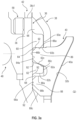
- FIG. 3a shows that relief grooves 92 can be provided at the connections between the surfaces 60b and 64a, between the surfaces 64a and 62c, and/or between the surfaces 62b and 68a, so that the connecting radii allow for better distribution of the mechanical forces and stresses during operation.
- the contact surfaces 60b, 64a, 68a of the bowl 36 are always a little smaller than the faces 86a, 86b, 88b of the stops 40 opposite each other. This makes it possible to avoid a local force peak at the end of the bearing surface on the bowl 36 (radial and axial support).
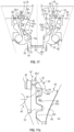
- FIGS. 17 and 17a represent an alternative embodiment of the system 34 and in particular of the stops 40' which here additionally include a finger 94 additional which extends axially on the side of the blade 12 of the vane 10 in the mounting position, and which comprises a lateral face 94a for bearing radially outwards.
- the faces 86a are intended to be applied axially to the surface 60b of the rib 60
- the faces 94a are intended to be applied axially to the surface 60a of this same rib 60.
- the other faces of the stops 40' are separated by clearances from the surfaces facing the bowl 36.
- the radial support (expansion work) of the stops 40' is made on the inside diameter of the upper rib 60.
- the area of the bowl 36 working in traction (retaining the blade 10 in centrifugal) is not exposed to this force.
- the radial support is made on a thicker part of the bowl 36, the deformation of the bowl 36 is less, benefiting the operation of the upper bearing 48.
- the axial support of the stops 40' is made on the lower surface 60b of the upper rib 60 of the bowl 36, isolating the critical zone of this support from the critical traction zone of the bowl 36 by a sufficient distance.
- stops 40, 40' are mounted one after the other by a dog-type assembly in the bowl 36. Furthermore, it is also understood that the stops 40, 40' are mounted one after the other in the bowl 36 in the same manner as the loading of bullets into the rotating barrel of a firearm, the bowl 36 here forming the barrel.
- the ring 38 is preferably moved by a circumferential pitch, this circumferential pitch being equal to 360°/k, k being the number of slots 76 of the intermediate wall 72 of the ring 38.
- this circumferential pitch represents 40° around the axis A.
Landscapes
- Engineering & Computer Science (AREA)
- Mechanical Engineering (AREA)
- General Engineering & Computer Science (AREA)
- Aviation & Aerospace Engineering (AREA)
- Structures Of Non-Positive Displacement Pumps (AREA)
Claims (19)
- System (34) zum Steuern der Winkelfeststellposition einer Schaufel (10) eines Propellers für ein Turbotriebwerk eines Luftfahrzeugs, umfassend:- eine Schaufel (10), umfassend ein mit einem Fuß (14) verbundenes Schaufelblatt (12), wobei die Schaufel (10) eine Feststellachse (A) umfasst und ihr Fuß (14) einen Bulbus (32) umfasst, der zwei, jeweils unteren (32a) und oberen (32b), Spannweiten aufweist, die sich um die Achse (A) herum erstrecken, und- eine Schale (36), die eine ringförmige Wand (36a) umfasst, die sich um die Achse (A) herum erstreckt, wobei diese ringförmige Wand (36a) ein unteres axiales Ende umfasst, das durch eine Bodenwand (36b) geschlossen wird, und ein oberes axiales Ende, das offen und konfiguriert ist, um die Montage des Fußes (14) der Schaufel (10) im Inneren der Schale (36) zu ermöglichen, wobei die Bodenwand (36b) eine Aussparung (52) umfasst, die einen nicht kreisförmigen Querschnitt aufweist und konfiguriert ist, um ein freies Ende (28) mit komplementärer Form des Fußes (14) derart aufzunehmen, dass die Schale (36) um die Achse (A) herum drehfest mit dem Fuß (14) verbunden ist,wobei das System weiter umfasst:- einen Stützring (38), der sich um die Achse (A) herum erstreckt und um den Fuß (14) herum und in der Schale (36) montiert ist, wobei dieser Stützring (38) eine untere Wand (74) umfasst, die sich in der Schale (36) befindet und die eine Öffnung (74a) umfasst, die von dem freien Ende (28) des Fußes (14) durchquert wird, wobei die untere Spannweite (32a) des Bulbus (32) des Fußes (14) konfiguriert ist, um von der dem Schaufelblatt (12) der Schaufel (10) gegenüberliegenden Seite mindestens in axialer Richtung gegen diese untere Wand (74) anzuliegen, wobei der Stützring (38) weiter eine durchbrochene mittlere Wand (72) und ein Gewinde (78) an einem oberen Ende umfasst,- Anschläge (40, 40'), die um die Achse (A) herum angeordnet sind und die um den Fuß (14) herum und in der Schale (36) montiert sind, wobei diese Anschläge (40, 40') in den Lumen (76) der mittleren Wand (72) und in mindestens einer Aufnahme (64, 68) der ringförmigen Wand (36a) der Schale (36) in Eingriff stehen, wobei die obere Spannweite (32b) des Bulbus (32) des Fußes (14) konfiguriert ist, um von der Seite des Schaufelblatts (12) der Schaufel (10) mindestens in axialer Richtung gegen diese Anschläge (40, 40') anzuliegen, und- eine Schraubenmutter (42), die in dem Gewinde (78) des Stützrings (38) verschraubt und konfiguriert ist, um derart axial an der Schale (36) anzuliegen, dass das Festziehen der Schraubenmutter (42) die Anlage der unteren Wand (74) des Stützrings (38) an der unteren Spannweite (32a) des Bulbus (32) des Fußes (14), die Anlage der oberen Spannweite (32b) dieses Bulbus (32) an den Anschlägen (40, 40') und die Anlage dieser Anschläge (40, 40') an komplementären Anlageoberflächen (60a, 60b, 64a, 68a) der mindestens einen Aufnahme (64, 68) der Schale (36) erzwingt.
- System (34) nach Anspruch 1, wobei die Anzahl der Anschläge (40, 40') kleiner als oder gleich der Anzahl an Lumen (76) der mittleren Wand (72) dieses Stützrings (38) ist, wobei jeder der Anschläge (40, 40') in einem dieser Lumen (76) in Eingriff steht.
- System (34) nach Anspruch 2, wobei die Anzahl der Anschläge (40, 40') zwischen 5 und 20 liegt.
- System (34) nach einem der vorstehenden Ansprüche, wobei die untere Wand (74) des Stützrings (38) eine von der Seite des Schaufelblatts (14) derart aufgeweitete allgemeine Kegelstumpfform aufweist, dass die Anlage der unteren Spannweite (32a) des Bulbus (32) des Fußes (14) an dieser unteren Wand (74) in Bezug auf die Achse (A) an jedem Punkt eine axiale Komponente und eine radiale Komponente aufweist.
- System (34) nach einem der vorstehenden Ansprüche, wobei jeder der Anschläge (40, 40') eine Anlagefläche (40a) an der oberen Spannweite (32b) des Bulbus (32) des Fußes (14) umfasst, wobei diese Anlagefläche (40a) derart angepasst ist, dass die Anlage in Bezug auf die Achse (A) an jedem Punkt eine axiale Komponente und eine radiale Komponente aufweist.
- System (34) nach einem der vorstehenden Ansprüche, wobei die Schraubenmutter (42) an der Außenseite des Stützrings (38) verschraubt ist und/oder axial an einem oberen freien Ende (36c) der Schale (36) anliegt.
- System (34) nach einem der vorstehenden Ansprüche, wobei jeder der Anschläge (40, 40') mindestens einen in Bezug auf die Achse (A) radial in Richtung der Außenseite hervorstehenden Finger (86, 88) umfasst, wobei der mindestens eine Finger (86, 88) eine obere Fläche (86a) zur axialen Anlage an einer Anlageoberfläche (60b) umfasst, die der mindestens einen Aufnahme (64) entspricht.
- System (34) nach dem vorstehenden Anspruch, wobei der mindestens eine Finger (86, 88) weiter eine seitliche Fläche (86b) zur radialen Anlage in Richtung der Außenseite an einer Anlageoberfläche (64a) umfasst, die der mindestens einen Aufnahme (64) entspricht.
- System (34) nach Anspruch 7 oder 8, wobei jeder der Anschläge (40, 40') zwei in Bezug auf die Achse (A) radial in Richtung der Außenseite hervorstehende und axial hintereinander angeordnete Finger (86, 88) umfasst.
- System (34) nach einem der vorstehenden Ansprüche, wobei die Schale (36) mindestens eine ringförmige Rippe (60, 62) umfasst, die sich um die Achse (A) herum erstreckt und die die mindestens eine Aufnahme (64, 68) zum Eingriff der Anschläge (40, 40') definiert, wobei diese Rippe (60, 62) mindestens eine axiale Einkerbung (70) umfasst, die konfiguriert ist, um die Montage der Anschläge (40, 40') einen nach dem anderen zu ermöglichen.
- System (34) nach Anspruch 10, wobei die Schale (36) zwei ringförmige, jeweils obere (60) und untere (62), Rippen umfasst, die sich um die Achse (A) herum erstrecken und die zwischen ihnen die mindestens eine Aufnahme (64) zum Eingriff der Anschläge (40, 40') definieren, wobei diese Rippen (60, 62) mindestens eine axiale Einkerbung (70) umfassen, die konfiguriert ist, um die Montage der Anschläge (40, 40') einen nach dem anderen zu ermöglichen.
- System (34) nach Anspruch 10 oder 11, wobei es weiter mindestens eine Verriegelung (44) umfasst, die in einem der Lumen (76) des Stützrings (38) in Eingriff steht, und in der mindestens einen Einkerbung (70) die Verriegelung (44) an dem Stützring (38) befestigt ist.
- System (34) nach Anspruch 12, wobei die Verriegelung (44) durch eine oder mehrere Schrauben (84) an dem Stützring (38) befestigt ist.
- System (34) nach Anspruch 12 oder 13, wobei sich die Verriegelung (44) auf der Seite einer Oberseite (12b) des Schaufelblatts (12) der Schaufel (10) befindet und näher an einer Abströmkante (12d) des Schaufelblatts (12) als an seiner Anströmkante (12a) vorliegt.
- System (34) nach einem der Ansprüche 12 bis 14, wobei vor der Montage der Verriegelung (44) der Stützring (38) in der Lage ist, sich in der Schale (36) drehend um die Achse (A) herum zu verschieben, und nach der Montage der Verriegelung (44) der Stützring (38) um diese Achse (A) herum durch umlaufenden Anschlag der Verriegelung (44) auf den Seiten der Einkerbung (70) drehend immobilisiert ist.
- Turbotriebwerk, insbesondere eines Luftfahrzeugs, das mindestens ein System (34) nach einem der vorstehenden Ansprüche umfasst.
- Verfahren zum Montieren eines Systems (34) nach einem der Ansprüche 1 bis 15, wobei es die Schritte umfasst zum:a) Einsetzen des Stützrings (38) in die Schale (36),b) Einsetzen des Fußes (14) der Schaufel (10) in den Stützring (38), bis zum Anlegen der unteren Spannweite (32a) des Bulbus (32) des Fußes (14) an der unteren Wand (74) des Stützrings (38),c) Einführen der Anschläge (40, 40') in die Lumen (76) der mittleren Wand (72) des Stützrings (38) und in die mindestens eine Aufnahme (64, 68) der Schale (36), undd) Verschraubung der Schraubenmutter (42) an dem Stützring (38) und Festziehen der Schraubenmutter (42) an der Schale (36) auf eine Weise, um die Anlage der unteren Wand (74) des Stützrings (38) an der unteren Spannweite (32a) des Bulbus (32) des Fußes (14), die Anlage der oberen Spannweite (32b) dieses Bulbus (32) an den Anschlägen (40, 40') und die Anlage dieser Anschläge (40, 40') an den komplementären Anlageoberflächen (60a, 60b, 64a, 68a) der mindestens einen Aufnahme (64, 68) der Schale (36) zu erzwingen.
- Verfahren nach Anspruch 17, wobei das System wie in Anspruch 15 definiert ist, wobei der Schritt c) die folgenden aufeinander folgenden Teilschritte umfasst:c1) Einführen eines der Anschläge (40, 40') in eins der Lumen (76) der mittleren Wand (72) des Stützrings (38) durch axiale translatorische Verschiebung des Anschlags (40, 40') quer durch die Einkerbung (70) der Schale (36),c2) drehende Verschiebung des Stützrings (38) und des Anschlags (40, 40') im Inneren der Schale (36) um die Achse (A) herum,c3) Einführen des anderen der Anschläge (40, 40') in eins der Lumen (76) der mittleren Wand (72) des Stützrings (38) durch axiale translatorische Verschiebung des Anschlags (40, 40') quer durch die Einkerbung (70) der Schale (36),c4) drehende Verschiebung des Stützrings (38) und der Anschläge (40, 40') im Inneren der Schale (36) um die Achse (A) herum,c5) Wiederholung der Schritte c3) und c4) für die verbleibenden Anschläge (40, 40'),c6) Einführen der Verriegelung (44) in das letzte frei Lumen (76) der mittleren Wand (72) des Stützrings durch axiale translatorische Verschiebung der Verriegelung (44) quer durch die Einkerbung (70) der Schale (36),c7) Befestigung der Verriegelung (44) an dem Stützring (38).
- Verfahren nach Anspruch 18, wobei der Stützring (38) bei jedem der Schritte c2) und c4) um einen umlaufenden Schritt verschoben wird, wobei dieser umlaufende Schritt gleich 360°/k ist, wobei k die Anzahl von Lumen (76) der mittleren Wand (72) des Stützrings (38) ist.
Applications Claiming Priority (1)
| Application Number | Priority Date | Filing Date | Title |
|---|---|---|---|
| PCT/FR2021/051500 WO2023031522A1 (fr) | 2021-08-31 | 2021-08-31 | Système de commande du calage angulaire d'une aube d'helice pour une turbomachine d'aeronef |
Publications (2)
| Publication Number | Publication Date |
|---|---|
| EP4396077A1 EP4396077A1 (de) | 2024-07-10 |
| EP4396077B1 true EP4396077B1 (de) | 2025-05-28 |
Family
ID=78086607
Family Applications (1)
| Application Number | Title | Priority Date | Filing Date |
|---|---|---|---|
| EP21790227.9A Active EP4396077B1 (de) | 2021-08-31 | 2021-08-31 | System zur steuerung der blattverstellung eines propellers für ein flugzeugturbinentriebwerk |
Country Status (4)
| Country | Link |
|---|---|
| US (1) | US12331647B2 (de) |
| EP (1) | EP4396077B1 (de) |
| CN (1) | CN117980226A (de) |
| WO (1) | WO2023031522A1 (de) |
Families Citing this family (4)
| Publication number | Priority date | Publication date | Assignee | Title |
|---|---|---|---|---|
| US12264590B2 (en) * | 2023-08-08 | 2025-04-01 | General Electric Company | Fan assembly for an engine having redundant trunnion retention |
| FR3154462B1 (fr) | 2023-10-19 | 2025-09-26 | Safran Aircraft Engines | Aube a calage variable pour une helice de turbomachine d’aeronef |
| FR3154701B1 (fr) * | 2023-10-25 | 2025-10-31 | Safran Aircraft Engines | Ensemble pour une helice de turbomachine d’aeronef |
| US12546226B1 (en) | 2024-08-07 | 2026-02-10 | General Electric Company | Variable pitch fan blade retention system |
Family Cites Families (9)
| Publication number | Priority date | Publication date | Assignee | Title |
|---|---|---|---|---|
| US4850801A (en) * | 1987-12-21 | 1989-07-25 | United Technologies Corporation | Aircraft propeller blade retention |
| FR2942454B1 (fr) * | 2009-02-23 | 2012-09-14 | Airbus France | Dispositif de retenue d'aube pour helice de turbomachine. |
| FR2943985B1 (fr) | 2009-04-07 | 2011-05-13 | Airbus France | Helice pour turbomachine d'aeronef comprenant un anneau de retention d'aubes monte autour du moyeu. |
| FR2958621B1 (fr) * | 2010-04-09 | 2012-03-23 | Snecma | Helice non carenee pour turbomachine. |
| FR3017163B1 (fr) | 2014-02-04 | 2016-02-12 | Snecma | Dispositif pour une helice non carenee a pales a calage variable d'une turbomachine |
| FR3021030B1 (fr) * | 2014-05-14 | 2018-01-05 | Ratier Figeac | Pale a ancrage securise en translation radiale, helice, turbomachine et aeronef |
| FR3046403B1 (fr) * | 2016-01-05 | 2018-02-09 | Safran Aircraft Engines | Pivot de pale a orientation reglable pour moyeu de soufflante de turbomachine |
| FR3080322B1 (fr) | 2018-04-20 | 2020-03-27 | Safran Aircraft Engines | Aube comprenant une structure en materiau composite et procede de fabrication associe |
| FR3093076B1 (fr) | 2019-02-22 | 2021-04-02 | Safran Aircraft Engines | Pivot d’aube à orientation réglable et à encombrement réduit pour moyeu de soufflante de turbomachine |
-
2021
- 2021-08-31 CN CN202180102548.5A patent/CN117980226A/zh active Pending
- 2021-08-31 WO PCT/FR2021/051500 patent/WO2023031522A1/fr not_active Ceased
- 2021-08-31 US US18/686,008 patent/US12331647B2/en active Active
- 2021-08-31 EP EP21790227.9A patent/EP4396077B1/de active Active
Also Published As
| Publication number | Publication date |
|---|---|
| WO2023031522A1 (fr) | 2023-03-09 |
| US12331647B2 (en) | 2025-06-17 |
| EP4396077A1 (de) | 2024-07-10 |
| CN117980226A (zh) | 2024-05-03 |
| US20250035009A1 (en) | 2025-01-30 |
Similar Documents
| Publication | Publication Date | Title |
|---|---|---|
| EP4185518B1 (de) | Flugzeugturbinentriebwerk mit verstellpropellerschaufeln | |
| EP4396077B1 (de) | System zur steuerung der blattverstellung eines propellers für ein flugzeugturbinentriebwerk | |
| EP4185778B1 (de) | Anordnung mit einer schaufel und einem system zur winkeleinstellung der schaufel | |
| EP4110691B1 (de) | Fanrotor mit schaufeln mit variablem anstellwinkel und mit einem solchen rotor ausgestattete turbomaschine | |
| EP4185521B1 (de) | Flugzeugturbinentriebwerk mit verstellpropellerschaufeln | |
| FR3146327A1 (fr) | Ensemble comportant une aube et un systeme de calage angulaire de l'aube | |
| FR3112819A1 (fr) | Turbomachine d’aeronef comportant des aubes d’helice a calage variable | |
| EP4185522B1 (de) | Flugzeugturbinentriebwerk mit verstellpropellerschaufeln | |
| EP4568886A1 (de) | Propeller für ein flugzeugturbinentriebwerk | |
| EP4522869B1 (de) | Flugzeugturbomaschine mit propellerschaufeln mit verstellbarem anstellwinkel | |
| EP4185523B1 (de) | System zur steuerung der blattverstellung eines propellers für ein flugzeugturbinentriebwerk | |
| EP4185520B1 (de) | System zur steuerung der neigung einer propellerschaufel für ein flugzeugturbinentriebwerk | |
| FR3131731A1 (fr) | Système de commande du calage angulaire d’une aube d’helice pour une turbomachine d’aeronef | |
| EP4402050B1 (de) | Propeller für eine flugzeugturbomaschine | |
| FR3120650A1 (fr) | Turbomachine d’aeronef comportant des aubes d’helice a calage variable | |
| FR3120660A1 (fr) | Système de commande du calage angulaire d’une aube d’helice pour une turbomachine d’aeronef | |
| FR3112820A1 (fr) | Turbomachine d’aeronef comportant des aubes d’helice a calage variable | |
| FR3123696A1 (fr) | Système de commande du calage angulaire d’une aube d’helice pour une turbomachine d’aeronef | |
| FR3121477A1 (fr) | Turbomachine d’aeronef comportant des aubes d’helice a calage variable | |
| WO2025062088A1 (fr) | Turbomachine d'aeronef comportant des aubes d'helice a calage variable | |
| WO2025088268A1 (fr) | Ensemble pour une helice de turbomachine d'aeronef |
Legal Events
| Date | Code | Title | Description |
|---|---|---|---|
| STAA | Information on the status of an ep patent application or granted ep patent |
Free format text: STATUS: UNKNOWN |
|
| STAA | Information on the status of an ep patent application or granted ep patent |
Free format text: STATUS: THE INTERNATIONAL PUBLICATION HAS BEEN MADE |
|
| PUAI | Public reference made under article 153(3) epc to a published international application that has entered the european phase |
Free format text: ORIGINAL CODE: 0009012 |
|
| STAA | Information on the status of an ep patent application or granted ep patent |
Free format text: STATUS: REQUEST FOR EXAMINATION WAS MADE |
|
| 17P | Request for examination filed |
Effective date: 20240228 |
|
| AK | Designated contracting states |
Kind code of ref document: A1 Designated state(s): AL AT BE BG CH CY CZ DE DK EE ES FI FR GB GR HR HU IE IS IT LI LT LU LV MC MK MT NL NO PL PT RO RS SE SI SK SM TR |
|
| DAV | Request for validation of the european patent (deleted) | ||
| DAX | Request for extension of the european patent (deleted) | ||
| GRAP | Despatch of communication of intention to grant a patent |
Free format text: ORIGINAL CODE: EPIDOSNIGR1 |
|
| STAA | Information on the status of an ep patent application or granted ep patent |
Free format text: STATUS: GRANT OF PATENT IS INTENDED |
|
| INTG | Intention to grant announced |
Effective date: 20250317 |
|
| GRAS | Grant fee paid |
Free format text: ORIGINAL CODE: EPIDOSNIGR3 |
|
| GRAA | (expected) grant |
Free format text: ORIGINAL CODE: 0009210 |
|
| STAA | Information on the status of an ep patent application or granted ep patent |
Free format text: STATUS: THE PATENT HAS BEEN GRANTED |
|
| AK | Designated contracting states |
Kind code of ref document: B1 Designated state(s): AL AT BE BG CH CY CZ DE DK EE ES FI FR GB GR HR HU IE IS IT LI LT LU LV MC MK MT NL NO PL PT RO RS SE SI SK SM TR |
|
| REG | Reference to a national code |
Ref country code: GB Ref legal event code: FG4D Free format text: NOT ENGLISH |
|
| REG | Reference to a national code |
Ref country code: CH Ref legal event code: EP |
|
| REG | Reference to a national code |
Ref country code: DE Ref legal event code: R096 Ref document number: 602021031475 Country of ref document: DE |
|
| REG | Reference to a national code |
Ref country code: IE Ref legal event code: FG4D Free format text: LANGUAGE OF EP DOCUMENT: FRENCH |
|
| REG | Reference to a national code |
Ref country code: NL Ref legal event code: MP Effective date: 20250528 |
|
| PG25 | Lapsed in a contracting state [announced via postgrant information from national office to epo] |
Ref country code: ES Free format text: LAPSE BECAUSE OF FAILURE TO SUBMIT A TRANSLATION OF THE DESCRIPTION OR TO PAY THE FEE WITHIN THE PRESCRIBED TIME-LIMIT Effective date: 20250528 Ref country code: FI Free format text: LAPSE BECAUSE OF FAILURE TO SUBMIT A TRANSLATION OF THE DESCRIPTION OR TO PAY THE FEE WITHIN THE PRESCRIBED TIME-LIMIT Effective date: 20250528 |
|
| PGFP | Annual fee paid to national office [announced via postgrant information from national office to epo] |
Ref country code: DE Payment date: 20250819 Year of fee payment: 5 |
|
| REG | Reference to a national code |
Ref country code: LT Ref legal event code: MG9D |
|
| PG25 | Lapsed in a contracting state [announced via postgrant information from national office to epo] |
Ref country code: GR Free format text: LAPSE BECAUSE OF FAILURE TO SUBMIT A TRANSLATION OF THE DESCRIPTION OR TO PAY THE FEE WITHIN THE PRESCRIBED TIME-LIMIT Effective date: 20250829 Ref country code: NO Free format text: LAPSE BECAUSE OF FAILURE TO SUBMIT A TRANSLATION OF THE DESCRIPTION OR TO PAY THE FEE WITHIN THE PRESCRIBED TIME-LIMIT Effective date: 20250828 |
|
| PG25 | Lapsed in a contracting state [announced via postgrant information from national office to epo] |
Ref country code: NL Free format text: LAPSE BECAUSE OF FAILURE TO SUBMIT A TRANSLATION OF THE DESCRIPTION OR TO PAY THE FEE WITHIN THE PRESCRIBED TIME-LIMIT Effective date: 20250528 Ref country code: PL Free format text: LAPSE BECAUSE OF FAILURE TO SUBMIT A TRANSLATION OF THE DESCRIPTION OR TO PAY THE FEE WITHIN THE PRESCRIBED TIME-LIMIT Effective date: 20250528 |
|
| PG25 | Lapsed in a contracting state [announced via postgrant information from national office to epo] |
Ref country code: BG Free format text: LAPSE BECAUSE OF FAILURE TO SUBMIT A TRANSLATION OF THE DESCRIPTION OR TO PAY THE FEE WITHIN THE PRESCRIBED TIME-LIMIT Effective date: 20250528 |
|
| PGFP | Annual fee paid to national office [announced via postgrant information from national office to epo] |
Ref country code: GB Payment date: 20250825 Year of fee payment: 5 |
|
| PG25 | Lapsed in a contracting state [announced via postgrant information from national office to epo] |
Ref country code: HR Free format text: LAPSE BECAUSE OF FAILURE TO SUBMIT A TRANSLATION OF THE DESCRIPTION OR TO PAY THE FEE WITHIN THE PRESCRIBED TIME-LIMIT Effective date: 20250528 |
|
| PGFP | Annual fee paid to national office [announced via postgrant information from national office to epo] |
Ref country code: FR Payment date: 20250827 Year of fee payment: 5 |
|
| PG25 | Lapsed in a contracting state [announced via postgrant information from national office to epo] |
Ref country code: RS Free format text: LAPSE BECAUSE OF FAILURE TO SUBMIT A TRANSLATION OF THE DESCRIPTION OR TO PAY THE FEE WITHIN THE PRESCRIBED TIME-LIMIT Effective date: 20250828 |
|
| PG25 | Lapsed in a contracting state [announced via postgrant information from national office to epo] |
Ref country code: IS Free format text: LAPSE BECAUSE OF FAILURE TO SUBMIT A TRANSLATION OF THE DESCRIPTION OR TO PAY THE FEE WITHIN THE PRESCRIBED TIME-LIMIT Effective date: 20250928 |
|
| PG25 | Lapsed in a contracting state [announced via postgrant information from national office to epo] |
Ref country code: LV Free format text: LAPSE BECAUSE OF FAILURE TO SUBMIT A TRANSLATION OF THE DESCRIPTION OR TO PAY THE FEE WITHIN THE PRESCRIBED TIME-LIMIT Effective date: 20250528 |
|
| REG | Reference to a national code |
Ref country code: AT Ref legal event code: MK05 Ref document number: 1798511 Country of ref document: AT Kind code of ref document: T Effective date: 20250528 |
|
| PG25 | Lapsed in a contracting state [announced via postgrant information from national office to epo] |
Ref country code: DK Free format text: LAPSE BECAUSE OF FAILURE TO SUBMIT A TRANSLATION OF THE DESCRIPTION OR TO PAY THE FEE WITHIN THE PRESCRIBED TIME-LIMIT Effective date: 20250528 Ref country code: AT Free format text: LAPSE BECAUSE OF FAILURE TO SUBMIT A TRANSLATION OF THE DESCRIPTION OR TO PAY THE FEE WITHIN THE PRESCRIBED TIME-LIMIT Effective date: 20250528 Ref country code: SM Free format text: LAPSE BECAUSE OF FAILURE TO SUBMIT A TRANSLATION OF THE DESCRIPTION OR TO PAY THE FEE WITHIN THE PRESCRIBED TIME-LIMIT Effective date: 20250528 |
|
| PG25 | Lapsed in a contracting state [announced via postgrant information from national office to epo] |
Ref country code: CZ Free format text: LAPSE BECAUSE OF FAILURE TO SUBMIT A TRANSLATION OF THE DESCRIPTION OR TO PAY THE FEE WITHIN THE PRESCRIBED TIME-LIMIT Effective date: 20250528 |
|
| PG25 | Lapsed in a contracting state [announced via postgrant information from national office to epo] |
Ref country code: EE Free format text: LAPSE BECAUSE OF FAILURE TO SUBMIT A TRANSLATION OF THE DESCRIPTION OR TO PAY THE FEE WITHIN THE PRESCRIBED TIME-LIMIT Effective date: 20250528 |
|
| PG25 | Lapsed in a contracting state [announced via postgrant information from national office to epo] |
Ref country code: SK Free format text: LAPSE BECAUSE OF FAILURE TO SUBMIT A TRANSLATION OF THE DESCRIPTION OR TO PAY THE FEE WITHIN THE PRESCRIBED TIME-LIMIT Effective date: 20250528 |
|
| PG25 | Lapsed in a contracting state [announced via postgrant information from national office to epo] |
Ref country code: IT Free format text: LAPSE BECAUSE OF FAILURE TO SUBMIT A TRANSLATION OF THE DESCRIPTION OR TO PAY THE FEE WITHIN THE PRESCRIBED TIME-LIMIT Effective date: 20250528 |
|
| REG | Reference to a national code |
Ref country code: DE Ref legal event code: R097 Ref document number: 602021031475 Country of ref document: DE |
|
| PG25 | Lapsed in a contracting state [announced via postgrant information from national office to epo] |
Ref country code: RO Free format text: LAPSE BECAUSE OF FAILURE TO SUBMIT A TRANSLATION OF THE DESCRIPTION OR TO PAY THE FEE WITHIN THE PRESCRIBED TIME-LIMIT Effective date: 20250528 |
|
| REG | Reference to a national code |
Ref country code: CH Ref legal event code: H13 Free format text: ST27 STATUS EVENT CODE: U-0-0-H10-H13 (AS PROVIDED BY THE NATIONAL OFFICE) Effective date: 20260324 |
|
| PG25 | Lapsed in a contracting state [announced via postgrant information from national office to epo] |
Ref country code: MC Free format text: LAPSE BECAUSE OF FAILURE TO SUBMIT A TRANSLATION OF THE DESCRIPTION OR TO PAY THE FEE WITHIN THE PRESCRIBED TIME-LIMIT Effective date: 20250528 |
|
| PLBE | No opposition filed within time limit |
Free format text: ORIGINAL CODE: 0009261 |
|
| STAA | Information on the status of an ep patent application or granted ep patent |
Free format text: STATUS: NO OPPOSITION FILED WITHIN TIME LIMIT |
|
| REG | Reference to a national code |
Ref country code: CH Ref legal event code: L10 Free format text: ST27 STATUS EVENT CODE: U-0-0-L10-L00 (AS PROVIDED BY THE NATIONAL OFFICE) Effective date: 20260409 |
|
| PG25 | Lapsed in a contracting state [announced via postgrant information from national office to epo] |
Ref country code: LU Free format text: LAPSE BECAUSE OF NON-PAYMENT OF DUE FEES Effective date: 20250831 |
|
| PG25 | Lapsed in a contracting state [announced via postgrant information from national office to epo] |
Ref country code: CH Free format text: LAPSE BECAUSE OF NON-PAYMENT OF DUE FEES Effective date: 20250831 |