EP4396477B1 - Gleitringdichtungsanordnung mit drehmomentmesseinrichtung sowie verfahren hierzu - Google Patents
Gleitringdichtungsanordnung mit drehmomentmesseinrichtung sowie verfahren hierzu Download PDFInfo
- Publication number
- EP4396477B1 EP4396477B1 EP22751386.8A EP22751386A EP4396477B1 EP 4396477 B1 EP4396477 B1 EP 4396477B1 EP 22751386 A EP22751386 A EP 22751386A EP 4396477 B1 EP4396477 B1 EP 4396477B1
- Authority
- EP
- European Patent Office
- Prior art keywords
- torque
- mechanical seal
- sliding surfaces
- slide ring
- seal assembly
- Prior art date
- Legal status (The legal status is an assumption and is not a legal conclusion. Google has not performed a legal analysis and makes no representation as to the accuracy of the status listed.)
- Active
Links
Images


Classifications
-
- F—MECHANICAL ENGINEERING; LIGHTING; HEATING; WEAPONS; BLASTING
- F16—ENGINEERING ELEMENTS AND UNITS; GENERAL MEASURES FOR PRODUCING AND MAINTAINING EFFECTIVE FUNCTIONING OF MACHINES OR INSTALLATIONS; THERMAL INSULATION IN GENERAL
- F16J—PISTONS; CYLINDERS; SEALINGS
- F16J15/00—Sealings
- F16J15/16—Sealings between relatively-moving surfaces
- F16J15/34—Sealings between relatively-moving surfaces with slip-ring pressed against a more or less radial face on one member
- F16J15/3492—Sealings between relatively-moving surfaces with slip-ring pressed against a more or less radial face on one member with monitoring or measuring means associated with the seal
-
- F—MECHANICAL ENGINEERING; LIGHTING; HEATING; WEAPONS; BLASTING
- F16—ENGINEERING ELEMENTS AND UNITS; GENERAL MEASURES FOR PRODUCING AND MAINTAINING EFFECTIVE FUNCTIONING OF MACHINES OR INSTALLATIONS; THERMAL INSULATION IN GENERAL
- F16J—PISTONS; CYLINDERS; SEALINGS
- F16J15/00—Sealings
- F16J15/16—Sealings between relatively-moving surfaces
- F16J15/34—Sealings between relatively-moving surfaces with slip-ring pressed against a more or less radial face on one member
- F16J15/3464—Mounting of the seal
-
- G—PHYSICS
- G01—MEASURING; TESTING
- G01M—TESTING STATIC OR DYNAMIC BALANCE OF MACHINES OR STRUCTURES; TESTING OF STRUCTURES OR APPARATUS, NOT OTHERWISE PROVIDED FOR
- G01M13/00—Testing of machine parts
- G01M13/005—Sealing rings
Definitions
- the present invention relates to a mechanical seal arrangement with a torque measuring device and a method for checking wear of sliding surfaces of a mechanical seal arrangement.
- Mechanical seal assemblies are known from the prior art in various designs.
- One problem area with mechanical seal assemblies is the determination of the wear condition of the sliding surfaces of the seal rings.
- the mechanical seal is usually a non-contact seal during normal operation, with a gas cushion or a liquid cushion between the sliding surfaces of the stationary and rotating seal rings, situations also arise during operation in which contact exists between the seal rings, for example, when starting up or shutting down the machine, or from the moment the machine starts until the seal surfaces lift off. Pressure surges acting in the axial direction of the mechanical seal can also occur during operation, creating contact between the seal surfaces. However, such contact can damage the seal surfaces and necessitate replacement of the seal rings. It is known, for example, that wear of the seal surfaces is determined based on leakage across the seal gap.
- the mechanical seal assembly according to the invention with the features of claim 1 has the advantage that an alternative and simple-to-implement wear detection on sliding surfaces of a rotating and/or stationary seal ring of a mechanical seal is possible.
- a direct torque measurement of a torque applied to the stationary seal ring is possible both during test operation on a test bench and when the mechanical seal is installed for sealing on a shaft or the like.
- the mechanical seal assembly has a mechanical seal with a rotating and stationary seal ring, which define a sealing gap between their sliding surfaces.
- a torque measuring device is provided, which is configured to detect a torque applied to the stationary seal ring.
- the torque measuring device comprises a measuring unit and a sensor.
- the measuring unit is fixed by a base to a housing of the mechanical seal and is arranged with a free end in a groove formed in an outer circumference of the stationary seal ring.
- the sensor is configured to detect a change in position of the measuring unit in the groove.
- the change in position of the measuring unit is a measure of the torque exerted on the stationary seal ring.
- the torque value measured on the stationary seal ring provides information about the wear status of the sliding surfaces of the rotating and stationary seal rings. This enables simple and reliable detection of the condition of the sliding surfaces and, if necessary, rapid replacement of the seal rings.
- the torque measuring device enables reliable torque measurement even during axial movements of the stationary sliding ring, which can occur during operation due to pressure surges or the like.
- the mechanical seal assembly further comprises a control device configured to determine wear on the sliding surfaces of the mechanical seal based on the detected torque on the stationary sliding ring.
- the control device is particularly preferably configured to determine the wear on the sliding surfaces of the sliding rings as a function of the torque level. For example, a threshold value for a torque can be stored in a database, and the threshold value can be compared with the detected torque value. If the threshold value is exceeded, this indicates excessive wear on the sliding surfaces, and the control unit can, for example, output a replacement signal or a replacement message or the like.
- control device is designed to operate the mechanical seal arrangement in such a way that contact occurs at the sliding surfaces of the rotating and stationary seal ring and the torque measuring device detects a torque occurring when the sliding surfaces come into contact. Contact torque is recorded and, based on the contact torque, a conclusion is drawn about wear on the sliding surfaces. Determining the torque upon contact between the sliding surfaces is particularly informative with regard to wear on the sliding surfaces. This can occur, for example, at a low speed of a shaft to be sealed, when there is no or insufficient medium in the sealing gap for the sliding surfaces of the seal rings to lift off.
- the measuring unit is preferably designed as a flat bar.
- the measuring unit thus comprises a flat, rod-shaped beam fixed on one side, the length of which is greater than its cross-sectional dimensions.
- the cross-section of the flat bar is preferably rectangular. Since the free end of the flat bar is arranged in the groove in the stationary slide ring and the foot of the flat bar is fixed in place to the housing, when a torque is introduced onto the stationary slide ring, the stationary slide ring is moved in the circumferential direction, so that the free end of the flat bar experiences a change in position upon contact with a groove wall. This change in position is a measure of the torque introduced into the stationary slide ring, on the basis of which wear of the sliding surfaces of the slide rings can be determined.
- a protruding region in particular a cam-shaped region, is formed at the free end of each flat side of the flat bar.
- the flat bar then has a width in the groove that is only minimally smaller than the groove width, so that when a torque is introduced into the stationary sliding ring, the free end of the flat bar immediately changes position. This allows even small torques to be reliably detected.
- the base of the measuring unit has a greater thickness than the free end.
- the thickness at the base of the measuring unit is twice as large as the thickness at the free end.
- the sensor of the torque measuring device is particularly preferably an optical sensor.
- the optical sensor detects position changes of the free end of the measuring unit due to the torque introduced into the stationary sliding ring.
- the optical sensor is preferably of the reflection type, which detects a light beam, for example a laser beam, reflected from the free end of the measuring unit.
- the optical sensor is an optical FBG sensor (Fiber Bragg Grating).
- the optical sensors have the particular advantage that no electrical current is required for the measurement at the measuring unit, so that they are preferably used for sealing tasks with explosion hazard. or similar. If the measuring unit is designed as a flat bar, a special reflection surface for the optical sensor is preferably formed on at least one flat side of the flat bar. This can, in particular, increase measurement accuracy.
- the torque measuring device's sensor is a strain gauge (SG).
- Strain gauge sensors are very cost-effective and have a very robust design. Strain gauge sensors can be used, for example, in sealing applications where a large number of dust particles or similar substances are present, where optical measurement methods produce poor results.
- piezo element the sensor for the torque measuring device.
- Piezo elements are also very robust and relatively inexpensive to produce. Since electrical current also flows through piezo sensors, their application is usually limited to gaseous media where electrical short circuits do not occur.
- the stationary seal ring is preloaded in the axial direction by means of a preloading device.
- a pressure ring is provided between the preloading device and the stationary seal ring.
- the preloading device is particularly preferably a plurality of individual spring elements arranged along the circumference of the mechanical seal.
- the control unit is further preferably configured to detect a breakaway torque of the mechanical seal when the mechanical seal is at a standstill.
- the mechanical seal is at a standstill, the sliding surfaces of the rotating and stationary seal rings touch each other.
- the breakaway torque is reached when the rotating seal ring begins to rotate relative to the stationary seal ring. This can be determined reliably and easily using the torque measuring device according to the invention.
- the greater the breakaway torque of the mechanical seal arrangement the more wear there is on the sliding surfaces of the seal rings. If a threshold value for the breakaway torque is exceeded, it can then again be concluded that excessive wear has occurred and that the seal rings need to be replaced.
- the present invention relates to a method for checking wear of sliding surfaces of a mechanical seal assembly according to the invention as described above.
- the method comprises the steps of detecting a torque acting on the stationary seal ring and comparing the detected torque with a stored torque threshold. If the torque is greater than the torque threshold, it is determined that excessive wear of the sliding surfaces is present.
- the method according to the invention enables the advantages described above.
- the method further comprises the steps of operating the mechanical seal assembly at a speed such that the sliding surfaces of the rotating and stationary seal rings are in contact.
- a contact torque acting on the stationary seal ring upon contact of the sliding surfaces is detected, and the detected contact torque is compared with a stored threshold value for the contact torque. If the contact torque is greater than the threshold value, it is determined that excessive wear of the sliding surfaces is present.
- a signal or message can then preferably be output, and the seal rings can be replaced.
- the method according to the invention detects a breakaway torque from a standstill of the mechanical seal as a contact torque.
- the breakaway torque is the torque value at which a relative rotation of the rotating seal ring to the stationary seal ring begins.
- the torque on the stationary seal ring is also continuously recorded during operation of the mechanical seal.
- a certain torque is always exerted on the stationary seal ring during operation, which also increases with increasing wear of the sliding surfaces. Therefore, the recorded torque during operation is also an indicator of the wear of the sliding surfaces of the seal rings, and a comparison with a stored threshold value can then indicate the need to replace the seal rings if the threshold is exceeded.
- the mechanical seal arrangement 1 comprises, as shown in Fig. 1 shown, a mechanical seal 2 with a rotating seal ring 3 and a stationary seal ring 4.
- a sealing gap 5 is defined between a sliding surface 3a of the rotating seal ring 3 and a sliding surface 4a of the stationary seal ring 4. During operation, there is usually no contact between the sliding surfaces 3a, 4a of the seal rings.
- the mechanical seal arrangement 1 seals a product area 13 from an atmospheric area 14 on a shaft 17.
- the rotating slide ring 3 is connected to the shaft 17 by means of a slide ring carrier 30, so that a rotation of the shaft is transmitted to the rotating slide ring 3 via the slide ring carrier 30.
- the stationary seal ring 4 is arranged on a housing 8 in a non-rotatable manner.
- the housing 8 has a sleeve region 80 extending in the axial direction XX of the mechanical seal arrangement 1.
- the stationary slide ring 4 is movable in the axial direction XX on the sleeve region 80.
- a pressure ring 11 is provided, which is preloaded in the axial direction XX against the rotating slide ring 3 by means of preloading elements 10, in particular a plurality of spring elements.
- the mechanical seal arrangement 1 comprises a torque measuring device 6.
- the torque measuring device 6 is shown in detail in the Fig. 1 to 4
- the torque measuring device 6 comprises a measuring unit 7 and a sensor 9, which in this embodiment is an optical sensor.
- the sensor 9 comprises a light guide 90 and a light source/receiver arrangement 91.
- the light source/receiver arrangement 91 emits a light into the light guide 90 and receives a corresponding reflection.
- the measuring unit 7 is shown in detail in summary from the Fig. 1 and 3
- the measuring unit 7 comprises a flat bar 70, which is fastened on one side to the housing 8.
- the flat bar 70 is fastened on one side by means of a base plate 73, which is fixed to the housing 8 with screw bolts 15, 16.
- a free end 71 of the flat bar 70 projects into a groove 40 formed on an outer circumference of the stationary slide ring 4.
- a foot 72 connected to the base plate has a greater thickness than the free end 71 (cf. Fig. 3 ).
- the groove 40 runs in the axial direction XX of the mechanical seal arrangement 1.
- the free end 71 extends in the axial direction XX from the base plate 73 through the entire groove 40 and has a small overhang in the axial direction over the groove 40.
- the light guide 90 is also guided to the groove 40, whereby the light guide 90 has a 90° bend (cf. Fig. 2 ).
- a reflection surface 75 is provided on a flat side 71a at the free end 71 of the flat bar 70 (cf. Fig. 2 ).
- a light beam (arrow A) emitted by the light source/receiver arrangement 91 is reflected and sent back to it.
- protruding areas 74 are provided on both sides of the flat bar 70 (see in particular Fig. 2 and 3 ), which are also arranged in the groove 40.
- the projecting areas 74 are designed such that a small gap 18 is present on both sides to the walls of the groove 40 ( Fig. 2 ).
- the stationary seal ring 4 can perform axial movements. For example, when the shaft 17 moves in Fig. 1 to the left, which also causes a movement of the rotating sliding ring 3 in the axial direction, a readjustment is made possible by the preload force F applied by the preload element 10 via the pressure ring 11. As can be seen from Fig. 3 As can be seen, the torque measuring device 6, which is fixed to the housing 8, remains stationary, but the measuring recording areas of the torque measuring device 6 are still arranged in the groove 40 of the stationary slide ring 4.
- the function and measuring method of the torque detection device 6 is as follows: During normal operation of the mechanical seal assembly 1, when a medium is present in the sealing gap 5 and there is no contact between the sliding surfaces 3a, 4a of the sliding rings 3, 4 is present, a torque is exerted on the stationary sliding ring 4, which is shown schematically in Figure 4 As indicated by arrow B, a groove wall 40a of the groove 40 comes into contact with the measuring unit 7, in particular one of the protruding areas 74. As a result, there is no longer a gap 18 between the groove wall 40a and the protruding area 74.
- the sensor 9 is connected to a control device 12, which evaluates the sensor signal. The torque exerted on the stationary slide ring 4 can be determined from the change in the sensor signal.
- the control device 12 is further configured to compare the torque value thus determined with a torque threshold value. If the determined torque value is above the threshold value, this is a clear indication of wear on the sliding surfaces 3a, 4a, since with unworn sliding surfaces 3a, 4a, the torque transmission from the rotating sliding ring 3 to the stationary sliding ring 4 is much lower than with sliding surfaces that exhibit wear, for example, scoring or waviness or the like.
- a torque measurement can also be carried out when there is contact between the rotating seal ring and the stationary seal ring at the sliding surfaces 3a, 4a, for example when the shaft 17 is at a standstill or at a very low speed at which contact is still present at the sliding surfaces 3a, 4a.
- the contact between the sliding surfaces lasts longer than with new seal surfaces.
- the torque transmitted from the rotating seal ring 3 to the stationary seal ring 4 is significantly greater than with new seal rings, which exhibit no wear and no waviness.
- a breakaway torque can also be measured when the shaft 17 is at a standstill, which is also significantly greater with worn sliding surfaces than with a sliding surface with no or only slight wear.
- the stationary sliding ring 4 has a radially outwardly directed, circumferential flange area 41 in which the groove 40 is formed.
- the flange area 41 has no sliding surface (see also Fig. 4 ).
- the circumferential force thus generated during torque transmission from the rotating seal ring 3 to the stationary seal ring 4 acts on the flat bar 70, causing it to bend and deform.
- This deformation can be detected by optical displacement measurement.
- the control device 12 is configured, for example, based on to determine a force on the measuring unit 7 based on the known material parameters of the measuring unit 7 and then to calculate the torque acting on the stationary sliding ring 4 based on the known sliding ring geometry.
- the measuring unit 7 is preferably made of stainless steel.
- Fig. 5 shows a mechanical seal assembly 1 according to a second embodiment of the invention. Identical or functionally identical parts are designated by the same reference numerals as in the first embodiment.
- the second embodiment essentially corresponds to the first embodiment, with a strain gauge 92 being used as sensor 9 instead of an optical sensor in the second embodiment.
- the strain gauge 92 is arranged in the area of the base 72 of the flat bar 70.
- This change can be detected by the control device 12, and from this, the force acting on the measuring unit 7 due to the torque introduced into the stationary sliding ring 4 can be determined.
- this exemplary embodiment corresponds to the previous exemplary embodiment, so that reference can be made to the description given there.
- an optical FBG sensor can also be used at the position of the strain gauge 92.
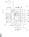
- Fig. 6 shows a mechanical seal arrangement 1 according to a third exemplary embodiment of the invention. Identical or functionally identical parts are designated by the same reference numerals as in the previous exemplary embodiments.
- a piezo sensor 93 is arranged as sensor 9 on a groove wall 40a of the groove 40.
- the measuring unit 7 bends, in particular, in the region of the free end 71. This can exert a force on the piezo sensor 93, causing its electrical resistance to change, which can be detected by the control device 12.
- the control device 12 can then determine the force exerted on the piezo sensor 93 and thus the torque based on the changed electrical resistance of the piezo sensor 93.
- piezo sensors 93 are preferably arranged on both groove walls of the groove 40. Otherwise, this embodiment corresponds to the previous embodiments, so that reference can be made to the description given there.
- the method according to the invention for checking the wear condition of sliding surfaces 3a, 4a is carried out in all of the described embodiments, in particular, upon contact between the sliding surfaces of the sliding rings.
- the various sensors 9 of the torque detection device 6 described in the embodiments can thus detect a contact torque upon contact between the sliding surfaces. This contact torque is then compared with a threshold value stored in the control device 12. As soon as the contact torque is greater than the threshold value, the control device 12 determines that excessive wear of the sliding surfaces 3a, 4a of the sliding rings is present. A signal or message can then be output, for example, indicating the excessive wear and recommending replacement of the sliding rings.
- the method according to the invention can be used, in particular, to detect a breakaway torque of the sliding surfaces when the shaft 17 is at a standstill. If the breakaway torque is also greater than a predetermined threshold value for the breakaway torque, excessive wear of the sliding surfaces can also be concluded, and corresponding indications can be issued by the control device 12.
Landscapes
- Engineering & Computer Science (AREA)
- General Engineering & Computer Science (AREA)
- Mechanical Engineering (AREA)
- Physics & Mathematics (AREA)
- General Physics & Mathematics (AREA)
- Mechanical Sealing (AREA)
- Testing Of Devices, Machine Parts, Or Other Structures Thereof (AREA)
Description
- Die vorliegende Erfindung betrifft eine Gleitringdichtungsanordnung mit einer Drehmomentmesseinrichtung sowie ein Verfahren zum Überprüfen eines Verschleißes von Gleitflächen einer Gleitringdichtungsanordnung.
- Gleitringdichtungsanordnungen aus dem Stand der Technik in unterschiedlichen Ausgestaltungen bekannt. Ein Problemkreis bei Gleitringdichtungsanordnungen ist die Bestimmung eines Verschleißzustandes der Gleitflächen der Gleitringe. Zwar ist die Gleitringdichtung im Normalbetrieb üblicherweise eine berührungslose Dichtung, wobei zwischen den Gleitflächen des stationären und des rotierenden Gleitrings ein Gaspolster oder ein Flüssigkeitspolster vorhanden ist, allerdings ergeben sich auch im Betrieb Situationen, bei denen ein Kontakt zwischen den Gleitringen vorhanden ist, beispielsweise beim Anfahren oder Abstellen der Maschine oder vom Zeitpunkt des Starts der Maschine bis zum Abheben der Gleitflächen. Auch können im Betrieb in Axialrichtung der Gleitringdichtung wirkende Druckstöße auftreten, welche einen Kontakt zwischen den Gleitflächen herstellen. Derartige Kontakte können jedoch die Gleitflächen beschädigen und einen Austausch der Gleitringe notwendig machen. Es ist bekannt, dass beispielsweise ein Verschleiß der Gleitflächen anhand einer Leckage über den Dichtspalt bestimmt wird. Es wäre jedoch wünschenswert, auch alternative Möglichkeiten zur Bestimmung eines Zustandes von Gleitflächen zu haben. Aus der
US 2005 / 0 016 303 A1 ist eine Gleitringdichtungsanordnung gemäß dem Oberbegriff des Anspruchs 1 bekannt. Ferner zeigen dieDE 10 2018 206 219 B3 , dieJP H02 199374 A CN 102 183 327 A Gleitringdichtungsanordnungen mit Sensoreinrichtungen zur Messung von verschiedenen Größen einer Gleitringdichtungsanordnung. - Es ist daher Aufgabe der vorliegenden Erfindung, eine Gleitringdichtungsanordnung sowie ein Verfahren zum Überprüfen eines Verschleißzustandes von Gleitflächen bereitzustellen, welche bei einfachem Aufbau und einfacher kostengünstiger Herstellbarkeit eine schnelle und sichere Verschleißbestimmung der Gleitflächen ermöglichen.
- Diese Aufgabe wird durch eine Gleitringdichtungsanordnung mit den Merkmalen des Anspruchs 1 sowie ein Verfahren mit den Merkmalen des Anspruchs 11 gelöst. Die Unteransprüche zeigen jeweils bevorzugte Weiterbildungen der Erfindung.
- Die erfindungsgemäße Gleitringdichtungsanordnung mit den Merkmalen des Anspruchs 1 weist demgegenüber den Vorteil auf, dass eine alternative und einfach auszuführende Verschleißerkennung an Gleitflächen eines rotierenden und/oder stationären Gleitrings einer Gleitringdichtung möglich ist. Insbesondere ist eine direkte Drehmomentmessung eines am stationären Gleitring anliegenden Drehmoments sowohl in einem Testbetrieb auf einem Prüfstand als auch im eingebauten Zustand der Gleitringdichtung zur Abdichtung an einer Welle oder dgl. möglich. Dies wird erfindungsgemäß dadurch erreicht, dass die Gleitringdichtungsanordnung eine Gleitringdichtung mit rotierendem und stationären Gleitring aufweist, welche zwischen ihren Gleitflächen einen Dichtspalt definieren. Ferner ist eine Drehmomentmesseinrichtung vorgesehen, welche eingerichtet ist, ein am stationären Gleitring anliegendes Drehmoment zu erfassen. Die Drehmomentmesseinrichtung umfasst dabei eine Messeinheit und einen Sensor. Die Messeinheit ist mit einem Fuß an einem Gehäuse der Gleitringdichtung fixiert und mit einem freien Ende in einer in einem Außenumfang des stationären Gleitrings ausgebildeten Nut angeordnet. Der Sensor ist eingerichtet, eine Positionsänderung der Messeinheit in der Nut zu erfassen. Die Positionsänderung der Messeinheit ist dabei ein Maß für das auf den stationären Gleitring ausgeübte Drehmoment. Der erfasste Drehmomentwert am stationären Gleitring gibt dabei Aufschluss über einen Verschleißzustand der Gleitflächen des rotierenden und stationären Gleitrings. Somit kann eine einfache und sichere Erfassung des Zustands der Gleitflächen ermöglicht werden und gegebenenfalls ein schneller Austausch der Gleitringe durchgeführt werden.
- Insbesondere ermöglicht die erfindungsgemäße Drehmomentmesseinrichtung eine sichere Drehmomentmessung auch bei axialen Bewegungen des stationären Gleitrings, welche im Betrieb durch Druckstöße oder dgl. auftreten können.
- Ferner umfasst die Gleitringdichtungsanordnung eine Steuereinrichtung, welche eingerichtet ist, basierend auf dem erfassten Drehmoment am stationären Gleitring auf einen Verschleiß der Gleitflächen der Gleitringdichtung zu schließen. Die Steuereinrichtung ist insbesondere bevorzugt eingerichtet, den Verschleiß der Gleitflächen der Gleitringe in Abhängigkeit einer Höhe des Drehmoments zu bestimmen. Hierbei kann beispielsweise ein Schwellenwert für ein Drehmoment in einer Datenbank hinterlegt sein und ein Vergleich des Schwellenwerts mit dem erfassten Drehmomentwert erfolgen. Wenn der Schwellenwert überschritten ist, ist dies ein Hinweis auf einen übermäßigen Verschleiß der Gleitflächen und die Steuereinheit kann beispielsweise ein Austauschsignal oder eine Austauschmeldung oder dgl. ausgeben.
- Weiterhin ist die Steuereinrichtung eingerichtet, die Gleitringdichtungsanordnung derart zu betreiben, dass ein Kontakt an den Gleitflächen des rotierenden und stationären Gleitrings auftritt und die Drehmomentmesseinrichtung ein bei Kontakt der Gleitflächen auftretendes Kontaktdrehmoment erfasst und basierend auf dem Kontaktdrehmoment auf einen Verschleiß der Gleitflächen schließt. Die Bestimmung des Drehmoments bei einem Kontakt der Gleitflächen ist besonders aufschlussreich hinsichtlich eines Verschleißes der Gleitflächen. Dies kann beispielsweise bei einer niedrigen Drehzahl einer abzudichtenden Welle auftreten, wenn im Dichtspalt noch kein oder nicht ausreichend Medium für ein Abheben der Gleitflächen der Gleitringe vorhanden ist.
- Somit kann eine sichere Drehmomenterfassung auch bei axial beweglichen stationären Gleitringen ermöglicht werden.
- Vorzugsweise ist die Messeinheit als Flachstab ausgebildet. Die Messeinheit umfasst somit einen flachen, stabförmig ausgebildeten, einseitig fixierten Balken, dessen Länge größer ist als dessen Querschnittsabmessungen. Der Querschnitt des Flachstabs ist vorzugsweise rechteckig. Da das freie Ende des Flachstabs in der Nut im stationären Gleitring eingeordnet ist und der Fuß des Flachstabs am Gehäuse ortsfest fixiert ist, wird bei Einleitung eines Drehmoments auf den stationären Gleitring der stationäre Gleitring in Umfangsrichtung bewegt, so dass das freie Ende des Flachstabs bei Kontakt mit einer Nutwand eine Positionsänderung erfährt. Diese Positionsänderung ist ein Maß für das in den stationären Gleitring eingeleitete Drehmoment, aufgrund dessen dann auf einen Verschleiß der Gleitflächen der Gleitringe geschlossen werden kann.
- Vorzugsweise ist am freien Ende an jeder Flachseite des Flachstabs jeweils ein vorstehender Bereich, insbesondere ein nockenförmiger Bereich, ausgebildet. Vorzugsweise weist der Flachstab dabei dann in der Nut eine Breite auf, welche nur minimal kleiner als die Nutbreite ist, so dass bei einer Einleitung eines Drehmoments in den stationären Gleitring gleich eine Ortsveränderung des freien Endes des Flachstabs erfolgt. Dadurch können auch kleine Drehmomente sicher erfasst werden.
- Weiter bevorzugt weist der Fuß der Messeinheit eine größere Dicke auf als das freie Ende. Vorzugsweise ist die Dicke am Fuß der Messeinheit doppelt so groß wie die Dicke am freien Ende.
- Besonders bevorzugt ist der Sensor der Drehmomentmesseinrichtung ein optischer Sensor. Der optische Sensor erfasst dabei Positionsänderungen des freien Endes der Messeinheit aufgrund des in den stationären Gleitrings eingeleiteten Drehmoments. Vorzugsweise ist der optische Sensor vom Reflexionstyp, welcher einen vom freien Ende der Messeinheit reflektierten Lichtstrahl, beispielsweise ein Laserstrahl, erfasst. Alternativ ist der optische Sensor ein optischer FBG-Sensor (Fiber Bragg Gitter). Die optischen Sensoren haben insbesondere den Vorteil, dass zur Messung an der Messeinheit kein elektrischer Strom notwendig ist, so dass diese vorzugsweise bei Abdichtungsaufgaben mit Explosionsgefahr oder ähnlichem eingesetzt werden. Wenn die Messeinheit als Flachstab ausgebildet ist, ist vorzugsweise an wenigstens einer Flachseite des Flachstabs eine spezielle Reflexionsfläche für den optischen Sensor ausgebildet. Hierdurch kann insbesondere eine Messgenauigkeit erhöht werden.
- Alternativ ist der Sensor der Drehmomentmesseinrichtung ein Dehnungsmessstreifen (DMS). DMS-Sensoren sind sehr kostengünstig bereitstellbar und sehr robust aufgebaut. DMS-Sensoren können beispielsweise bei Abdichtungsaufgaben eingesetzt werden, wenn eine Vielzahl von Staubpartikeln oder ähnliches vorhanden ist, bei denen optische Messverfahren nur schlechte Ergebnisse liefern.
- Weiter alternativ ist der Sensor der Drehmomentmesseinrichtung ein Piezoelement. Piezoelemente sind ebenfalls sehr robust und relativ kostengünstig bereitstellbar. Da auch bei Piezosensoren elektrischer Strom fließt, ist das Anwendungsgebiet üblicherweise auf gasförmige Medien beschränkt, bei denen kein elektrischer Kurzschluss auftritt.
- Ein besonders einfacher und kostengünstiger Aufbau ist möglich, wenn die Nut im stationären Gleitring in Axialrichtung der Gleitringdichtungsanordnung verläuft. Die Nut ist somit parallel mit einer Mittelachse einer abzudichtenden Welle.
- Weiter bevorzugt ist der stationäre Gleitring mittels einer Vorspanneinrichtung in Axialrichtung vorgespannt. Vorzugsweise ist hierbei ein Druckring zwischen der Vorspanneinrichtung und dem stationären Gleitring vorgesehen. Die Vorspanneinrichtung ist besonders bevorzugt eine Vielzahl von einzelnen Federelementen, welche entlang des Umfangs der Gleitringdichtung angeordnet sind.
- Weiter bevorzugt ist die Steuereinheit eingerichtet, ein Losbrech-Drehmoment der Gleitringdichtung aus einem Stillstand der Gleitringdichtung zu erfassen. Im Stillstand der Gleitringdichtung berühren sich die Gleitflächen des rotierenden und stationären Gleitrings. Das Losbrech-Drehmoment ist dann erreicht, wenn sich der rotierende Gleitring gegenüber dem stationären Gleitring beginnt zu drehen. Dieses kann mit der erfindungsgemäßen Drehmomentmesseinrichtung sicher und einfach bestimmt werden. Auch hierbei gilt, je größer das Losbrech-Drehmoment der Gleitringdichtungsanordnung ist, umso mehr Verschleiß liegt an den Gleitflächen der Gleitringe vor. Bei Überschreiten eines Schwellenwerts für das Losbrech-Drehmoment kann dann ebenfalls wieder auf einen übermäßigen Verschleiß und einen notwendigen Austausch der Gleitringe geschlossen werden.
- Weiterhin betrifft die vorliegende Erfindung ein Verfahren zum Überprüfen eines Verschleißes von Gleitflächen einer wie vorangehend beschriebenen, erfindungsgemäßen Gleitringdichtungsanordnung. Das Verfahren umfasst dabei die Schritte des Erfassens eines auf den stationären Gleitring wirkenden Drehmoments und des Vergleichens des erfassten Drehmoments mit einem gespeicherten Schwellenwert für das Drehmoment. Wenn das Drehmoment größer als der Schwellenwert für das Drehmoment ist, wird bestimmt, dass ein übermäßiger Verschleiß der Gleitflächen vorliegt. Das erfindungsgemäße Verfahren ermöglicht dabei die voranstehend beschriebenen Vorteile.
- Weiter umfasst das Verfahren dabei die Schritte des Betreibens der Gleitringdichtungsanordnung mit einer Drehzahl derart, dass sich die Gleitflächen des rotierenden und stationären Gleitrings in Kontakt befinden. Dabei wird ein auf den stationären Gleitring bei Kontakt der Gleitflächen auftretendes Kontaktdrehmoment erfasst und das erfasste Kontaktdrehmoment mit einem gespeicherten Schwellenwert für das Kontaktdrehmoment verglichen. Wenn das Kontaktdrehmoment größer als der Schwellenwert ist, wird bestimmt, dass ein übermäßiger Verschleiß der Gleitflächen vorhanden ist. Dann kann vorzugsweise ein Signal oder eine Meldung ausgegeben werden und ein Austausch der Gleitringe erfolgen.
- Besonders bevorzugt erfasst das erfindungsgemäße Verfahren ein Losbrech-Drehmoment aus einem Stillstand der Gleitringdichtung als Kontaktdrehmoment. Das Losbrech-Drehmoment ist wie vorangehend beschrieben, dabei der Drehmomentwert, bei welchem eine Relativrotation des rotierenden Gleitrings zum stationären Gleitring beginnt.
- Vorzugsweise wird das Drehmoment am stationären Gleitring auch kontinuierlich während des Betriebs der Gleitringdichtung erfasst. Zwar herrscht beim Normalbetrieb der Gleitringdichtung kein direkter Kontakt an den Gleitflächen zwischen den Gleitringen, jedoch wird im Betrieb immer ein gewisses Drehmoment auf den stationären Gleitring ausgeübt, welches bei einem zunehmenden Verschleiß der Gleitflächen auch ansteigt. Von daher ist das erfasste Drehmoment im Betrieb ebenfalls ein Indikator für den Verschleiß der Gleitflächen der Gleitringe und ein Vergleich mit einem abgespeicherten Schwellenwert kann dann bei Überschreiten des Schwellenwerts der Hinweis auf den notwendigen Austausch der Gleitringe geben.
- Nachfolgend werden unter Bezugnahme auf die begleitende Zeichnungen Ausführungsbeispiele der Erfindung im Detail beschrieben. In der Zeichnung ist:
- Fig. 1
- eine schematische Schnittansicht einer Gleitringdichtungsanordnung gemäß einem ersten Ausführungsbeispiel der Erfindung,
- Fig. 2
- eine schematische Teil-Draufsicht auf die Gleitringdichtungsanordnung von
Fig. 1 , - Fig. 3
- eine perspektivische Teil-Ansicht der Gleitringdichtungsanordnung von
Fig. 1 , - Fig. 4
- eine Teil-Seitenansicht der Gleitringdichtungsanordnung von
Fig. 1 , - Fig. 5
- eine schematische Schnittansicht einer Gleitringdichtungsanordnung gemäß einem zweiten Ausführungsbeispiel der Erfindung, und
- Fig. 6
- eine schematische Schnittansicht einer Gleitringdichtungsanordnung gemäß einem dritten Ausführungsbeispiel der Erfindung.
- Nachfolgend wird unter Bezugnahme auf die
Fig. 1 bis 4 eine Gleitringdichtungsanordnung 1 sowie ein Verfahren zum Überprüfen eines Verschleißes von Gleitflächen der Gleitringdichtungsanordnung im Detail beschrieben. - Die Gleitringdichtungsanordnung 1 umfasst, wie in
Fig. 1 gezeigt, eine Gleitringdichtung 2 mit einem rotierenden Gleitring 3 und einem stationären Gleitring 4. Zwischen einer Gleitfläche 3a des rotierenden Gleitrings 3 und einer Gleitfläche 4a des stationären Gleitrings 4 ist ein Dichtspalt 5 definiert. Im Betrieb herrscht üblicherweise kein Kontakt zwischen den Gleitflächen 3a, 4a der Gleitringe. - Die Gleitringdichtungsanordnung 1 dichtet dabei an einer Welle 17 einen Produktbereich 13 von einem Atmosphärenbereich 14 ab.
- Der rotierende Gleitring 3 ist mittels eines Gleitringträgers 30 mit der Welle 17 verbunden, so dass eine Rotation der Welle über den Gleitringträger 30 auf den rotierenden Gleitring 3 übertragen wird.
- Der stationäre Gleitring 4 ist an einem Gehäuse 8 in nicht rotierbarer Weise angeordnet. Wie aus
Fig. 1 ersichtlich ist, weist das Gehäuse 8 einen in Axialrichtung X-X der Gleitringdichtungsanordnung 1 verlaufenden Hülsenbereich 80 auf. Dabei ist der stationäre Gleitring 4 in Axialrichtung X-X auf dem Hülsenbereich 80 bewegbar. An einer Rückseite 4b des stationären Gleitrings 4 ist ein Druckring 11 vorgesehen, welcher mittels Vorspannelementen 10, insbesondere einer Vielzahl von Federelementen, in Axialrichtung X-X gegen den rotierenden Gleitring 3 vorgespannt wird. - Weiterhin umfasst die Gleitringdichtungsanordnung 1 eine Drehmomentmesseinrichtung 6. Die Drehmomentmesseinrichtung 6 ist im Detail aus den
Fig. 1 bis 4 ersichtlich. Die Drehmomentmesseinrichtung 6 umfasst eine Messeinheit 7 und einen Sensor 9, welcher in diesem Ausführungsbeispiel ein optischer Sensor ist. Der Sensor 9 umfasst dabei einen Lichtleiter 90 und eine Lichtquelle-/Empfängeranordnung 91. Die Lichtquelle-/Empfängeranordnung 91 sendet ein Licht in den Lichtleiter 90 aus und empfängt eine entsprechende Reflexion. - Die Messeinheit 7 ist im Detail in Zusammenschau aus den
Fig. 1 und3 ersichtlich. Die Messeinheit 7 umfasst einen Flachstab 70, welcher einseitig am Gehäuse 8 befestigt ist. Hierbei ist der Flachstab 70 mittels einer Basisplatte 73, die mit Schraubbolzen 15, 16 am Gehäuse 8 fixiert ist, einseitig befestigt. Ein freies Ende 71 des Flachstabs 70 ragt in eine Nut 40, welche an einem Außenumfang des stationären Gleitrings 4 ausgebildet ist. Ein mit der Basisplatte verbundener Fuß 72 weist eine größere Dicke als das freie Ende 71 auf (vgl.Fig. 3 ). - Wie insbesondere aus
Fig. 1 ersichtlich ist, verläuft die Nut 40 in Axialrichtung X-X der Gleitringdichtungsanordnung 1. Wie weiter ausFig. 1 ersichtlich ist, reicht dabei das freie Ende 71 in Axialrichtung X-X ausgehend von der Basisplatte 73 durch die gesamte Nut 40 hindurch und weist einen kleinen Überstand in Axialrichtung über die Nut 40 auf. - Wie in
Fig. 1 gestrichelt dargestellt, ist auch der Lichtleiter 90 bis zur Nut 40 geführt, wobei der Lichtleiter 90 einen 90°-Bogen aufweist (vgl.Fig. 2 ). Hierbei ist an einer Flachseite 71a am freien Ende 71 des Flachstabs 70 eine Reflexionsfläche 75 vorgesehen (vgl.Fig. 2 ). Dadurch wird ein von der Lichtquelle-/Empfangsanordnung 91 ausgesandter Lichtstrahl (Pfeil A) reflektiert und zu dieser zurückgesendet. - Am Flachstab 70 sind ferner zu beiden Seiten vorstehende Bereiche 74 vorgesehen (vgl. insbesondere
Fig. 2 und3 ), welche ebenfalls in der Nut 40 angeordnet sind. Die vorstehenden Bereiche 74 sind dabei derart ausgelegt, dass ein kleiner Spalt 18 an beiden Seiten zu den Wänden der Nut 40 vorhanden ist (Fig. 2 ). - Da die Nut 40 geradlinig und parallel zur Axialrichtung X-X im stationären Gleitring 4 ausgebildet ist, kann der stationäre Gleitring 4 Axialbewegungen ausführen. Beispielsweise kann bei einer Bewegung der Welle 17 in
Fig. 1 nach links, welche auch eine Bewegung des rotierenden Gleitrings 3 in Axialrichtung verursacht, ein Nachsetzen durch die von dem Vorspannelement 10 aufgebrachten Vorspannkraft F über den Druckring 11 ermöglicht werden. Wie ausFig. 3 ersichtlich ist, bleibt dabei die Drehmomentmesseinrichtung 6, die am Gehäuse 8 fixiert ist, zwar ortsfest, jedoch sind Messaufnahmebereiche der Drehmomentmesseinrichtung 6 immer noch in der Nut 40 des stationären Gleitrings 4 angeordnet. - Die Funktion und das Messverfahren der Drehmomenterfassungseinrichtung 6 ist dabei wie folgt. Wenn im Normalbetrieb der Gleitringdichtungsanordnung 1, wenn im Dichtspalt 5 ein Medium vorhanden ist und kein Kontakt zwischen den Gleitflächen 3a, 4a der Gleitringe 3, 4 vorhanden ist, ein Drehmoment auf den stationären Gleitring 4 ausgeübt wird, was schematisch in
Figur 4 durch den Pfeil B angedeutet ist, kommt eine Nutwand 40a der Nut 40 mit der Messeinheit 7, insbesondere einem der vorstehenden Bereiche 74 in Kontakt. Damit ist kein Spalt 18 mehr zwischen der Nutwand 40a und dem vorstehenden Bereich 74 vorhanden. Dadurch erfolgt eine Verformung des Flachstabs 70 mit entsprechender Positionsänderung der Messeinheit 7, insbesondere am freien Ende 71, so dass der Sensor 9, welcher kontinuierlich oder im Intervall einen Lichtstrahl A aussendet, eine Änderung einer Reflexion des Lichtstrahls erfassen kann. Die Reflexionsänderung kann dann durch den Sensor 9 erfasst werden. Der Sensor 9 ist mit einer Steuereinrichtung 12 verbunden, welche eine Auswertung des Sensorsignals vornimmt. Aus der Änderung des Sensorsignals kann auf das auf den stationären Gleitring 4 ausgeübte Drehmoment geschlossen werden. - Die Steuereinrichtung 12 ist dabei ferner eingerichtet, den so ermittelten Drehmomentwert mit einem Schwellenwert für das Drehmoment zu vergleichen. Wenn der ermittelte Drehmomentwert über dem Schwellenwert liegt, ist dies ein deutlicher Hinweis auf einen Verschleiß an den Gleitflächen 3a, 4a, da bei nicht verschlissenen Gleitflächen 3a, 4a, eine Drehmomentübertragung vom rotierenden Gleitring 3 auf den stationären Gleitring 4 viel geringer ist, als bei Gleitflächen, welche einen Verschleiß, beispielsweise Riefen oder Welligkeiten oder dgl., aufweisen, haben.
- Auch bei einem Kontakt zwischen dem rotierenden Gleitring und dem stationären Gleitring an den Gleitflächen 3a, 4a, beispielsweise bei einem Stillstand der Welle 17 oder einer sehr geringen Drehzahl, bei der noch ein Kontakt an den Gleitflächen 3a, 4a vorhanden ist, kann eine Drehmomentmessung erfolgen. Bei verschlissenen Gleitringen hält der Kontakt zwischen den Gleitflächen länger an, als bei neuwertigen Gleitflächen. Somit ist ein vom rotierenden Gleitring 3 auf den stationären Gleitring 4 übertragenes Drehmoment deutlich größer als bei neuwertigen Gleitringen, welche keinen Verschleiß und keine Welligkeit aufweisen. Insbesondere kann aus einem Stillstand der Welle 17 auch ein Losbrech-Drehmoment erfasst werden, welches bei verschlissenen Gleitflächen ebenfalls deutlich größer ist als bei Gleitfläche ohne oder nur mit geringem Verschleiß.
- Wie insbesondere aus
Fig. 1 und4 weiter ersichtlich ist, weist der stationäre Gleitring 4 einen radial nach außen gerichteten, umlaufenden Flanschbereich 41 auf, in welchem die Nut 40 gebildet ist. Der Flanschbereich 41 weist dabei keine Gleitfläche auf (vgl. auchFig. 4 ). - Die somit bei Drehmomentübertragungen vom rotierenden Gleitring 3 auf den stationären Gleitring 4 ausgebildete Kraft in Umfangsrichtung wirkt auf den Flachstab 70, so dass dieser auf Biegung beansprucht wird und sich verformt. Diese Verformung kann durch eine optische Wegmessung erfasst werden. Die Steuereinrichtung 12 ist z.B. dabei eingerichtet, basierend auf den bekannten Materialparametern der Messeinheit 7 eine Kraft auf die Messeinheit 7 zu bestimmen und dann basierend auf der bekannten Gleitringgeometrie das am stationären Gleitring 4 anliegende Drehmoment zu berechnen.
- Durch die axiale Anordnung der Nut 40 kann dabei unabhängig von einer Axialposition des stationären Gleitrings 4 immer das am stationären Gleitring 4 anliegende Drehmoment erfasst werden. Die Messeinheit 7 ist vorzugsweise aus Edelstahl hergestellt.
-
Fig. 5 zeigt eine Gleitringdichtungsanordnung 1 gemäß einem zweiten Ausführungsbeispiel der Erfindung. Gleiche bzw. funktional gleiche Teile sind mit den gleichen Bezugszeichen wie im ersten Ausführungsbeispiel bezeichnet. Das zweite Ausführungsbeispiel entspricht im Wesentlichen dem ersten Ausführungsbeispiel, wobei statt eines optischen Sensors beim zweiten Ausführungsbeispiel als Sensor 9 ein Dehnungsmessstreifen 92 verwendet wird. Wie inFig. 5 gezeigt, ist der Dehnungsmessstreifen 92 am Bereich des Fußes 72 des Flachstabs 70 angeordnet. Wenn ein Drehmoment auf den stationären Gleitring 4 übertragen wird, erfolgt wie im ersten Ausführungsbeispiel eine Krafteinleitung auf das freie Ende 71 des Flachstabs 70 der Messeinheit 7, so dass sich ein elektrischer Widerstand des Dehnungsmessstreifens 92 in Abhängigkeit der Größe der Biegung des Flachstabs 70 ändert. Diese Änderung kann mittels der Steuereinrichtung 12 erfasst werden und daraus die auf die Messeinheit 7 wirkende Kraft aufgrund des in den stationären Gleitring 4 eingeleitete Drehmoment ermittelt werden. Ansonsten entspricht dieses Ausführungsbeispiel dem vorhergehenden Ausführungsbeispiel, so dass auf die dort gegebene Beschreibung verwiesen werden kann. Alternativ kann an der Position des Dehnungsmessstreifens 92 auch ein optischer FBG-Sensor verwendet werden. -
Fig. 6 zeigt eine Gleitringdichtungsanordnung 1 gemäß einem dritten Ausführungsbeispiel der Erfindung. Gleiche bzw. funktional gleiche Teile sind mit den gleichen Bezugszeichen wie in den vorhergehenden Ausführungsbeispielen bezeichnet. Beim dritten Ausführungsbeispiel ist als Sensor 9 eine Piezosensor 93 an einer Nutwand 40a der Nut 40 angeordnet. Wenn ein Drehmoment vom rotierenden Gleitring 3 auf den stationären Gleitring 4 übertragen wird, erfolgt eine Kraftübertragung auf die Messeinheit 7, welche sich insbesondere im Bereich des freien Endes 71 verbiegt. Dadurch kann eine Kraft auf den Piezosensor 93 ausgeübt werden, wodurch sich dessen elektrischer Widerstand ändert, was durch die Steuereinrichtung 12 erfassbar ist. Die Steuereinrichtung 12 kann dann basierend auf dem geänderten elektrischen Widerstand des Piezosensors 93 die auf diesen ausgeübte Kraft und damit auf das Drehmoment bestimmt werden. Um eine drehrichtungsunabhängige Erfassung des Drehmoments zu ermöglichen, sind vorzugsweise an beiden Nutwänden der Nut 40 Piezosensoren 93 angeordnet. Ansonsten entspricht dieses Ausführungsbeispiel den vorhergehenden Ausführungsbeispielen, so dass auf die dort gegebene Beschreibung verwiesen werden kann. - Das erfindungsgemäße Verfahren zum Überprüfen eines Verschleißzustands von Gleitflächen 3a, 4a wird in allen beschriebenen Ausführungsbeispielen dabei insbesondere bei einem Kontakt zwischen den Gleitflächen der Gleitringe ausgeübt. Durch die in den Ausführungsbeispielen beschriebenen verschiedenen Sensoren 9 der Drehmomenterfassungseinrichtung 6 kann somit bei Kontakt der Gleitflächen ein Kontaktdrehmoment erfasst werden. Dieses Kontaktdrehmoment wird dann mit einem in der Steuereinrichtung 12 gespeicherten Schwellenwert verglichen. Sobald das Kontaktdrehmoment größer als der Schwellenwert ist, bestimmt die Steuereinrichtung 12 dann, dass ein übermäßiger Verschleiß der Gleitflächen 3a, 4a der Gleitringe vorhanden ist. Hier kann dann beispielsweise ein Signal oder eine Meldung ausgegeben werden, welche auf den zu großen Verschleiß hinweist und einen Austausch der Gleitringe empfiehlt.
- Weiterhin kann durch das erfindungsgemäße Verfahren insbesondere ein Losbrech-Drehmoment der Gleitflächen aus einem Stillstand der Welle 17 erfasst werden. Wenn das Losbrech-Drehmoment ebenfalls größer als ein vorbestimmter Schwellenwert für das Losbrech-Drehmoment ist, kann ebenfalls auf einen übermäßigen Verschleiß der Gleitflächen geschlossen werden und entsprechende Hinweise durch die Steuereinrichtung 12 ausgegeben werden.
-
- 1
- Gleitringdichtungsanordnung
- 2
- Gleitringdichtung
- 3
- rotierender Gleitring
- 3a
- Gleitfläche des rotierenden Gleitrings
- 4
- stationärer Gleitring
- 4a
- Gleitfläche des rotierenden Gleitrings
- 4b
- Rückseite des stationären Gleitrings
- 5
- Dichtspalt
- 6
- Drehmomentmesseinrichtung
- 7
- Messeinheit
- 8
- Gehäuse
- 9
- Sensor
- 10
- Vorspannelement
- 11
- Druckring
- 12
- Steuereinrichtung
- 13
- Produktbereich
- 14
- Atmosphärenbereich
- 15, 16
- Schraubbolzen
- 17
- Welle
- 18
- Spalt zwischen Nutwand und Messeinheit
- 30
- Gleitringträger
- 40
- Nut
- 40a
- Nutwand
- 41
- Flanschbereich
- 70
- Flachstab
- 71
- freies Ende
- 71a
- Flachseite
- 72
- Fuß des Flachstabs
- 73
- Basisplatte
- 74
- vorstehender Bereich
- 75
- Reflexionsfläche
- 80
- Hülsenbereich
- 90
- Lichtleiter
- 91
- Lichtquelle-/Empfängeranordnung
- 92
- Dehnungsmessstreifen
- 93
- Piezosensor
- A
- Lichtstrahl
- B
- in den stationären Gleitring eingeleitete Kraft
- F
- Vorspannkraft
- X-X
- Axialrichtung
Claims (12)
- Gleitringdichtungsanordnung, umfassend:- eine Gleitringdichtung (2) mit einem rotierenden Gleitring (3) und einem stationären Gleitring (4), welche zwischen ihren Gleitflächen (3a, 4a) einen Dichtspalt (5) definieren, und- eine Drehmomentmesseinrichtung (6), welche eingerichtet ist, ein am stationären Gleitring (4) anliegendes Drehmoment zu erfassen,- dadurch gekennzeichnet, dass die Drehmomentmesseinrichtung (6) eine Messeinheit (7) und einen Sensor (9) umfasst, wobei die Messeinheit (7) mit einem Fuß (72) an einem Gehäuse (8) fixiert ist und ein freies Ende (71) aufweist, welches in einer in einem Außenumfang des stationären Gleitrings (4) ausgebildeten Nut (40) vorsteht, und- wobei der Sensor (9) eingerichtet ist, eine Positionsänderung der Messeinheit (7) in der Nut (40) zu erfassen,- eine Steuereinrichtung (12), welche eingerichtet ist, basierend auf dem erfassten Drehmoment am stationären Gleitring (4) auf einen Verschleiß der Gleitflächen (3a, 4a) der Gleitringdichtung (2) zu schließen, und- wobei die Steuereinrichtung (12) ferner eingerichtet ist, die Gleitringdichtungsanordnung (1) derart zu betreiben, dass ein Kontakt an den Gleitflächen (3a, 4a) zwischen dem rotierenden Gleitring (3) und dem stationären Gleitring (4) auftritt und weiter eingerichtet ist, ein bei Kontakt der Gleitflächen (3a, 4a) auftretendes Kontaktdrehmoment zu erfassen und basierend auf dem Kontaktdrehmoment auf einen Verschleiß der Gleitflächen zu schließen.
- Gleitringdichtungsanordnung nach Anspruch 1, wobei die Messeinheit (7) einen einseitig fixierten Flachstab (70) aufweist.
- Gleitringdichtungsanordnung nach einem der vorhergehenden Ansprüche, wobei am freien Ende (71) der Messeinheit (7) an jeder zu einer Nutwand (40a) der Nut (40) gerichteten Seite ein vorstehender Bereich (74) ausgebildet ist.
- Gleitringdichtungsanordnung nach einem der vorhergehenden Ansprüche, wobei der Fuß (72) der Messeinheit (7) eine größere Dicke aufweist als das freie Ende (71).
- Gleitringdichtungsanordnung nach einem der vorhergehenden Ansprüche, wobei der Sensor (9) ein optischer Sensor ist.
- Gleitringdichtungsanordnung nach Anspruch 5, wobei an der Messeinheit (7) eine Reflexionsfläche (75) für den optischen Sensor ausgebildet ist.
- Gleitringdichtungsanordnung nach einem der Ansprüche 1 bis 4, wobei der Sensor (9) einen Dehnungsmessstreifen (92) umfasst, welcher an der Messeinheit (7) angeordnet ist.
- Gleitringdichtungsanordnung nach einem der Ansprüche 1 bis 4, wobei der Sensor (9) einen Piezosensor (93) umfasst, welcher in der Nut (40) an der Nutwand (40a) angeordnet ist.
- Gleitringdichtungsanordnung nach einem der vorhergehenden Ansprüche,- wobei die Nut (40) in Axialrichtung (X-X) der Gleitringdichtungsanordnung (1) verläuft und/oder- wobei der stationäre Gleitring (4) mittels eines Vorspannelements (10) in Axialrichtung (X-X) vorgespannt ist.
- Gleitringdichtungsanordnung nach Anspruch 1, wobei die Steuereinrichtung (12) ferner eingerichtet ist, den Verschleiß der Gleitflächen (3a, 4a) basierend auf einem Vergleich des erfassten Drehmomentwerts mit einem Schwellenwert zu bestimmen, wenn der erfasste Drehmomentwert größer als der Schwellenwert ist.
- Verfahren zum Überprüfen eines Verschleißes von Gleitflächen (3a, 4a) einer Gleitringdichtungsanordnung, umfassend:- eine Gleitringdichtung (2) mit einem rotierenden Gleitring (3) und einem stationären Gleitring (4), welche zwischen ihren Gleitflächen (3a, 4a) einen Dichtspalt (5) definieren, und- eine Drehmomentmesseinrichtung (6), welche eingerichtet ist, ein am stationären Gleitring (4) anliegendes Drehmoment zu erfassen,- wobei die Drehmomentmesseinrichtung (6) eine Messeinheit (7) und einen Sensor (9) umfasst, wobei die Messeinheit (7) mit einem Fuß (72) an einem Gehäuse (8) fixiert ist und ein freies Ende (71) aufweist, welches in einer in einem Außenumfang des stationären Gleitrings (4) ausgebildeten Nut (40) vorsteht, und- wobei der Sensor (9) eingerichtet ist, eine Positionsänderung der Messeinheit (7) in der Nut (40) zu erfassen,umfassend die Schritte:- Betreiben der Gleitringdichtungsanordnung,- Erfassen eines auf den stationären Gleitring (4) wirkenden Drehmoments, und- Vergleichen des erfassen Drehmoments mit einem gespeicherten Schwellenwert für das Drehmoment,- wobei, wenn das Drehmoment größer als der Schwellenwert für das Drehmoment ist, bestimmt wird, dass ein übermäßiger Verschleiß der Gleitflächen (3a, 4a) vorliegt,- Betreiben der Gleitringdichtungsanordnung mit einer Drehzahl derart, dass sich die Gleitflächen (3a, 4a) des rotierenden Gleitrings (3) und des stationären Gleitrings (4) in Kontakt befinden,- Erfassen eines auf den stationären Gleitring (4) bei Kontakt der Gleitflächen auftretenden Kontaktdrehmoments, und- Vergleich des Kontaktdrehmoments mit einem gespeicherten Schwellenwert für das Kontaktdrehmoment,- wobei, wenn das Kontaktdrehmoment größer als der Schwellenwert für das Kontaktdrehmoment ist, bestimmt wird, dass ein übermäßiger Verschleiß der Gleitflächen (3a, 4a) vorhanden ist.
- Verfahren nach Anspruch 11, wobei ein Losbrech-Drehmoment der Gleitflächen, ausgehend aus einem Stillstand der Gleitringdichtung (2) erfasst wird und mit einem Schwellenwert für das Losbrech-Drehmoment verglichen wird und wenn das Losbrech-Drehmoment größer als der Schwellenwert für das Losbrech-Drehmoment ist, bestimmt wird, dass ein übermäßiger Verschleiß der Gleitflächen (3a, 4a) vorhanden ist.
Applications Claiming Priority (2)
| Application Number | Priority Date | Filing Date | Title |
|---|---|---|---|
| DE102021122476.4A DE102021122476A1 (de) | 2021-08-31 | 2021-08-31 | Gleitringdichtungsanordnung mit Drehmomentmesseinrichtung sowie Verfahren hierzu |
| PCT/EP2022/070217 WO2023030743A1 (de) | 2021-08-31 | 2022-07-19 | Gleitringdichtungsanordnung mit drehmomentmesseinrichtung sowie verfahren hierzu |
Publications (2)
| Publication Number | Publication Date |
|---|---|
| EP4396477A1 EP4396477A1 (de) | 2024-07-10 |
| EP4396477B1 true EP4396477B1 (de) | 2025-06-11 |
Family
ID=82839337
Family Applications (1)
| Application Number | Title | Priority Date | Filing Date |
|---|---|---|---|
| EP22751386.8A Active EP4396477B1 (de) | 2021-08-31 | 2022-07-19 | Gleitringdichtungsanordnung mit drehmomentmesseinrichtung sowie verfahren hierzu |
Country Status (9)
| Country | Link |
|---|---|
| US (1) | US12480581B2 (de) |
| EP (1) | EP4396477B1 (de) |
| JP (1) | JP7766179B2 (de) |
| CN (1) | CN117916501A (de) |
| AU (1) | AU2022337912B2 (de) |
| DE (1) | DE102021122476A1 (de) |
| ES (1) | ES3034632T3 (de) |
| PL (1) | PL4396477T3 (de) |
| WO (1) | WO2023030743A1 (de) |
Families Citing this family (1)
| Publication number | Priority date | Publication date | Assignee | Title |
|---|---|---|---|---|
| DE102019219422A1 (de) * | 2019-12-12 | 2021-06-17 | Eagleburgmann Germany Gmbh & Co. Kg | Gleitringdichtung mit Überwachungsfunktion sowie Verfahren hierzu |
Family Cites Families (14)
| Publication number | Priority date | Publication date | Assignee | Title |
|---|---|---|---|---|
| GB8319550D0 (en) * | 1983-07-20 | 1983-08-24 | Grange Packing Ltd | Seal wear indicator |
| JPH02199374A (ja) | 1989-01-30 | 1990-08-07 | Eagle Ind Co Ltd | メカニカルシールの特性変化計測方法およびその計測装置 |
| JP2681725B2 (ja) * | 1992-04-15 | 1997-11-26 | 株式会社タンケンシールセーコウ | メカニカルシールの挙動監視装置 |
| US6626436B2 (en) * | 1997-08-20 | 2003-09-30 | Crane John Inc | Monitoring seal system |
| US7405818B2 (en) * | 1998-06-03 | 2008-07-29 | Ralph Heinzen | Self monitoring static seal with optical sensor |
| GB0224862D0 (en) * | 2002-10-25 | 2002-12-04 | Aesseal Plc | An intelligent sealing system |
| DE202007001223U1 (de) | 2007-01-22 | 2007-05-03 | Burgmann Industries Gmbh & Co. Kg | Gleitringdichtung mit Überwachungsfunktion |
| EP2375111B1 (de) * | 2008-12-25 | 2015-10-21 | Kyocera Corporation | Gleitkomponente und mechanische dichtung, absperrhahn und rollenauflage damit |
| DE202009008089U1 (de) | 2009-06-10 | 2009-08-20 | Burgmann Industries Gmbh & Co. Kg | Gleitringdichtung mit Reibungsüberwachungseinrichtung |
| DE202009008088U1 (de) | 2009-06-10 | 2009-08-20 | Burgmann Industries Gmbh & Co. Kg | Gleitringdichtung mit druckgeschützter Überwachungseinrichtung |
| CN102183327B (zh) * | 2011-02-23 | 2013-01-23 | 南京林业大学 | 机械密封端面摩擦扭矩测量方法 |
| DE102017218711A1 (de) * | 2017-10-19 | 2019-04-25 | Christian Maier GmbH & Co. KG | Gleitringdichtung zur Abdichtung eines ein Fluid führenden Kanals und/oder Raumes und Verfahren zum Überwachen des Verschleißes einer Gleitringdichtung |
| DE102018206219B3 (de) * | 2018-04-23 | 2019-09-12 | Christian Maier GmbH & Co. KG | Dynamische Dichtung und Drehdurchführung mit einer solchen dynamischen Dichtung |
| DE102018215736B4 (de) * | 2018-09-17 | 2025-11-13 | Christian Maier GmbH & Co. KG, Maschinenfabrik | Drehdurchführung mit Gleitringdichtung |
-
2021
- 2021-08-31 DE DE102021122476.4A patent/DE102021122476A1/de active Pending
-
2022
- 2022-07-19 AU AU2022337912A patent/AU2022337912B2/en active Active
- 2022-07-19 ES ES22751386T patent/ES3034632T3/es active Active
- 2022-07-19 WO PCT/EP2022/070217 patent/WO2023030743A1/de not_active Ceased
- 2022-07-19 CN CN202280058475.9A patent/CN117916501A/zh active Pending
- 2022-07-19 JP JP2024513091A patent/JP7766179B2/ja active Active
- 2022-07-19 PL PL22751386.8T patent/PL4396477T3/pl unknown
- 2022-07-19 US US18/684,969 patent/US12480581B2/en active Active
- 2022-07-19 EP EP22751386.8A patent/EP4396477B1/de active Active
Also Published As
| Publication number | Publication date |
|---|---|
| US20250129850A1 (en) | 2025-04-24 |
| US12480581B2 (en) | 2025-11-25 |
| PL4396477T3 (pl) | 2025-10-06 |
| AU2022337912A1 (en) | 2024-03-14 |
| DE102021122476A1 (de) | 2023-03-02 |
| CN117916501A (zh) | 2024-04-19 |
| EP4396477A1 (de) | 2024-07-10 |
| ES3034632T3 (en) | 2025-08-20 |
| JP7766179B2 (ja) | 2025-11-07 |
| AU2022337912B2 (en) | 2025-03-06 |
| JP2024532357A (ja) | 2024-09-05 |
| WO2023030743A1 (de) | 2023-03-09 |
Similar Documents
| Publication | Publication Date | Title |
|---|---|---|
| DE69106032T2 (de) | Verfahren zur Vorhersage von Abweichungen in mechanischen Dichtungen und Gerät zu ihrer Vorhersage. | |
| EP2981796B1 (de) | Kraft-messvorrichtung | |
| EP3724540B1 (de) | Dynamische dichtung und drehdurchführung mit einer solchen dynamischen dichtung | |
| DE102016116113A1 (de) | Lager und Verfahren zur Verschleißüberwachung und/oder Lastmessung | |
| EP1800809A1 (de) | Bremsvorrichtung für einen Roboterantrieb und Verfahren zum Erkennen eines Bremsenzustandes | |
| EP4396477B1 (de) | Gleitringdichtungsanordnung mit drehmomentmesseinrichtung sowie verfahren hierzu | |
| WO2008089800A1 (de) | Gleitringdichtung mit überwachungsfunktion | |
| DE102018210842B4 (de) | Anordnung zur Aufnahme des Axialschubes einer Kreiselpumpe | |
| DE112006003783B4 (de) | Verfahren und Vorrichtung zur Lastmessung | |
| DE102013225467A1 (de) | Kugelgewindetrieb | |
| DE102006028294A1 (de) | Radiallageranordnung mit einer diese zentrierenden Spannringanordnung | |
| EP3643942B1 (de) | Bremsvorrichtung | |
| EP4652392A1 (de) | Gleitringdichtungsanordnung | |
| DE102019106572B4 (de) | Kraftmessvorrichtung, Getriebe und Stellantrieb sowie Verwendung einer Kraftmessvorrichtung | |
| WO1996035105A2 (de) | Vorrichtung zur ermittlung von auf einen messkopf wirkenden kräften und deren verwendung | |
| EP3999754B1 (de) | Brems- und/oder klemmvorrichtung mit einteiligem spaltgehäuse und sensormodul | |
| DE102013220429B4 (de) | Gleitringdichtungsanordnung mit optischer Überwachungseinrichtung und Verfahren zum Überwachen eines Dichtspaltes einer Gleitringdichtungsanordnung | |
| DE2755069A1 (de) | Vorrichtung zur ueberwachung der axialen auslenkung von turbomaschinenkupplungen | |
| EP4419818B1 (de) | Gleitring mit verschleiss-messeinrichtung sowie gleitringdichtungsanordnung mit derartigem gleitring | |
| WO1992002747A1 (de) | Anordnung zur abdichtung eines durchführungsspaltes zwischen einer gehäusewand und einer welle | |
| DE10206679C1 (de) | Vorrichtung zum Messen einer Axialkraft an einer Achse oder Welle | |
| DE202016000094U1 (de) | Richtpresse zum Richten von Rundlauf- oder Geradheitsfehlern an lang gestreckten Werkstücken mit mindestens einem Wendelbereich, wie an Förderschnecken, insbesondere an Extruderschnecken | |
| WO2023094331A1 (de) | Stellventileinheit mit einer zahnstrukturmessvorrichtung | |
| WO2023066651A1 (de) | GLEITRING MIT VERSCHLEIß-MESSEINRICHTUNG SOWIE GLEITRINGDICHTUNGSANORDNUNG MIT DERARTIGEM GLEITRING | |
| EP4321761A1 (de) | Erfassungseinrichtung, zylinderrohreinheit und verfahren zum erfassen einer position eines kolbens in einem zylinderrohr |
Legal Events
| Date | Code | Title | Description |
|---|---|---|---|
| STAA | Information on the status of an ep patent application or granted ep patent |
Free format text: STATUS: UNKNOWN |
|
| STAA | Information on the status of an ep patent application or granted ep patent |
Free format text: STATUS: THE INTERNATIONAL PUBLICATION HAS BEEN MADE |
|
| PUAI | Public reference made under article 153(3) epc to a published international application that has entered the european phase |
Free format text: ORIGINAL CODE: 0009012 |
|
| STAA | Information on the status of an ep patent application or granted ep patent |
Free format text: STATUS: REQUEST FOR EXAMINATION WAS MADE |
|
| 17P | Request for examination filed |
Effective date: 20240130 |
|
| AK | Designated contracting states |
Kind code of ref document: A1 Designated state(s): AL AT BE BG CH CY CZ DE DK EE ES FI FR GB GR HR HU IE IS IT LI LT LU LV MC MK MT NL NO PL PT RO RS SE SI SK SM TR |
|
| DAV | Request for validation of the european patent (deleted) | ||
| DAX | Request for extension of the european patent (deleted) | ||
| GRAP | Despatch of communication of intention to grant a patent |
Free format text: ORIGINAL CODE: EPIDOSNIGR1 |
|
| STAA | Information on the status of an ep patent application or granted ep patent |
Free format text: STATUS: GRANT OF PATENT IS INTENDED |
|
| INTG | Intention to grant announced |
Effective date: 20250317 |
|
| GRAS | Grant fee paid |
Free format text: ORIGINAL CODE: EPIDOSNIGR3 |
|
| GRAA | (expected) grant |
Free format text: ORIGINAL CODE: 0009210 |
|
| STAA | Information on the status of an ep patent application or granted ep patent |
Free format text: STATUS: THE PATENT HAS BEEN GRANTED |
|
| P01 | Opt-out of the competence of the unified patent court (upc) registered |
Free format text: CASE NUMBER: APP_17932/2025 Effective date: 20250414 |
|
| AK | Designated contracting states |
Kind code of ref document: B1 Designated state(s): AL AT BE BG CH CY CZ DE DK EE ES FI FR GB GR HR HU IE IS IT LI LT LU LV MC MK MT NL NO PL PT RO RS SE SI SK SM TR |
|
| REG | Reference to a national code |
Ref country code: GB Ref legal event code: FG4D Free format text: NOT ENGLISH |
|
| REG | Reference to a national code |
Ref country code: CH Ref legal event code: EP |
|
| REG | Reference to a national code |
Ref country code: DE Ref legal event code: R096 Ref document number: 502022004270 Country of ref document: DE |
|
| REG | Reference to a national code |
Ref country code: IE Ref legal event code: FG4D Free format text: LANGUAGE OF EP DOCUMENT: GERMAN |
|
| REG | Reference to a national code |
Ref country code: NL Ref legal event code: FP |
|
| REG | Reference to a national code |
Ref country code: ES Ref legal event code: FG2A Ref document number: 3034632 Country of ref document: ES Kind code of ref document: T3 Effective date: 20250820 |
|
| PGFP | Annual fee paid to national office [announced via postgrant information from national office to epo] |
Ref country code: NL Payment date: 20250804 Year of fee payment: 4 |
|
| PG25 | Lapsed in a contracting state [announced via postgrant information from national office to epo] |
Ref country code: FI Free format text: LAPSE BECAUSE OF FAILURE TO SUBMIT A TRANSLATION OF THE DESCRIPTION OR TO PAY THE FEE WITHIN THE PRESCRIBED TIME-LIMIT Effective date: 20250611 |
|
| PGFP | Annual fee paid to national office [announced via postgrant information from national office to epo] |
Ref country code: ES Payment date: 20250903 Year of fee payment: 4 |
|
| PGFP | Annual fee paid to national office [announced via postgrant information from national office to epo] |
Ref country code: DE Payment date: 20250804 Year of fee payment: 4 |
|
| REG | Reference to a national code |
Ref country code: LT Ref legal event code: MG9D |
|
| PG25 | Lapsed in a contracting state [announced via postgrant information from national office to epo] |
Ref country code: GR Free format text: LAPSE BECAUSE OF FAILURE TO SUBMIT A TRANSLATION OF THE DESCRIPTION OR TO PAY THE FEE WITHIN THE PRESCRIBED TIME-LIMIT Effective date: 20250912 Ref country code: NO Free format text: LAPSE BECAUSE OF FAILURE TO SUBMIT A TRANSLATION OF THE DESCRIPTION OR TO PAY THE FEE WITHIN THE PRESCRIBED TIME-LIMIT Effective date: 20250911 |
|
| PGFP | Annual fee paid to national office [announced via postgrant information from national office to epo] |
Ref country code: PL Payment date: 20250729 Year of fee payment: 4 Ref country code: IT Payment date: 20250731 Year of fee payment: 4 |
|
| PG25 | Lapsed in a contracting state [announced via postgrant information from national office to epo] |
Ref country code: BG Free format text: LAPSE BECAUSE OF FAILURE TO SUBMIT A TRANSLATION OF THE DESCRIPTION OR TO PAY THE FEE WITHIN THE PRESCRIBED TIME-LIMIT Effective date: 20250611 |
|
| PGFP | Annual fee paid to national office [announced via postgrant information from national office to epo] |
Ref country code: BE Payment date: 20250804 Year of fee payment: 4 |
|
| PG25 | Lapsed in a contracting state [announced via postgrant information from national office to epo] |
Ref country code: HR Free format text: LAPSE BECAUSE OF FAILURE TO SUBMIT A TRANSLATION OF THE DESCRIPTION OR TO PAY THE FEE WITHIN THE PRESCRIBED TIME-LIMIT Effective date: 20250611 |
|
| PGFP | Annual fee paid to national office [announced via postgrant information from national office to epo] |
Ref country code: AT Payment date: 20251020 Year of fee payment: 4 Ref country code: FR Payment date: 20250804 Year of fee payment: 4 |
|
| PG25 | Lapsed in a contracting state [announced via postgrant information from national office to epo] |
Ref country code: RS Free format text: LAPSE BECAUSE OF FAILURE TO SUBMIT A TRANSLATION OF THE DESCRIPTION OR TO PAY THE FEE WITHIN THE PRESCRIBED TIME-LIMIT Effective date: 20250911 |
|
| PG25 | Lapsed in a contracting state [announced via postgrant information from national office to epo] |
Ref country code: LV Free format text: LAPSE BECAUSE OF FAILURE TO SUBMIT A TRANSLATION OF THE DESCRIPTION OR TO PAY THE FEE WITHIN THE PRESCRIBED TIME-LIMIT Effective date: 20250611 |
|
| PG25 | Lapsed in a contracting state [announced via postgrant information from national office to epo] |
Ref country code: PT Free format text: LAPSE BECAUSE OF FAILURE TO SUBMIT A TRANSLATION OF THE DESCRIPTION OR TO PAY THE FEE WITHIN THE PRESCRIBED TIME-LIMIT Effective date: 20251013 |
|
| PG25 | Lapsed in a contracting state [announced via postgrant information from national office to epo] |
Ref country code: IS Free format text: LAPSE BECAUSE OF FAILURE TO SUBMIT A TRANSLATION OF THE DESCRIPTION OR TO PAY THE FEE WITHIN THE PRESCRIBED TIME-LIMIT Effective date: 20251011 |
|
| PG25 | Lapsed in a contracting state [announced via postgrant information from national office to epo] |
Ref country code: SM Free format text: LAPSE BECAUSE OF FAILURE TO SUBMIT A TRANSLATION OF THE DESCRIPTION OR TO PAY THE FEE WITHIN THE PRESCRIBED TIME-LIMIT Effective date: 20250611 |
|
| PG25 | Lapsed in a contracting state [announced via postgrant information from national office to epo] |
Ref country code: CZ Free format text: LAPSE BECAUSE OF FAILURE TO SUBMIT A TRANSLATION OF THE DESCRIPTION OR TO PAY THE FEE WITHIN THE PRESCRIBED TIME-LIMIT Effective date: 20250611 |
|
| PG25 | Lapsed in a contracting state [announced via postgrant information from national office to epo] |
Ref country code: EE Free format text: LAPSE BECAUSE OF FAILURE TO SUBMIT A TRANSLATION OF THE DESCRIPTION OR TO PAY THE FEE WITHIN THE PRESCRIBED TIME-LIMIT Effective date: 20250611 |
|
| PG25 | Lapsed in a contracting state [announced via postgrant information from national office to epo] |
Ref country code: SK Free format text: LAPSE BECAUSE OF FAILURE TO SUBMIT A TRANSLATION OF THE DESCRIPTION OR TO PAY THE FEE WITHIN THE PRESCRIBED TIME-LIMIT Effective date: 20250611 |
|
| REG | Reference to a national code |
Ref country code: CH Ref legal event code: H13 Free format text: ST27 STATUS EVENT CODE: U-0-0-H10-H13 (AS PROVIDED BY THE NATIONAL OFFICE) Effective date: 20260224 |
|
| PG25 | Lapsed in a contracting state [announced via postgrant information from national office to epo] |
Ref country code: RO Free format text: LAPSE BECAUSE OF FAILURE TO SUBMIT A TRANSLATION OF THE DESCRIPTION OR TO PAY THE FEE WITHIN THE PRESCRIBED TIME-LIMIT Effective date: 20250611 |
|
| PG25 | Lapsed in a contracting state [announced via postgrant information from national office to epo] |
Ref country code: LU Free format text: LAPSE BECAUSE OF NON-PAYMENT OF DUE FEES Effective date: 20250719 |
|
| PG25 | Lapsed in a contracting state [announced via postgrant information from national office to epo] |
Ref country code: MC Free format text: LAPSE BECAUSE OF FAILURE TO SUBMIT A TRANSLATION OF THE DESCRIPTION OR TO PAY THE FEE WITHIN THE PRESCRIBED TIME-LIMIT Effective date: 20250611 |
|
| PG25 | Lapsed in a contracting state [announced via postgrant information from national office to epo] |
Ref country code: DK Free format text: LAPSE BECAUSE OF FAILURE TO SUBMIT A TRANSLATION OF THE DESCRIPTION OR TO PAY THE FEE WITHIN THE PRESCRIBED TIME-LIMIT Effective date: 20250611 |
|
| PLBE | No opposition filed within time limit |
Free format text: ORIGINAL CODE: 0009261 |
|
| STAA | Information on the status of an ep patent application or granted ep patent |
Free format text: STATUS: NO OPPOSITION FILED WITHIN TIME LIMIT |
|
| REG | Reference to a national code |
Ref country code: CH Ref legal event code: L10 Free format text: ST27 STATUS EVENT CODE: U-0-0-L10-L00 (AS PROVIDED BY THE NATIONAL OFFICE) Effective date: 20260423 |