EP4397227A2 - Ensemble de nettoyage - Google Patents
Ensemble de nettoyage Download PDFInfo
- Publication number
- EP4397227A2 EP4397227A2 EP24167447.2A EP24167447A EP4397227A2 EP 4397227 A2 EP4397227 A2 EP 4397227A2 EP 24167447 A EP24167447 A EP 24167447A EP 4397227 A2 EP4397227 A2 EP 4397227A2
- Authority
- EP
- European Patent Office
- Prior art keywords
- base plate
- handle
- cleaning
- coupling
- diamond
- Prior art date
- Legal status (The legal status is an assumption and is not a legal conclusion. Google has not performed a legal analysis and makes no representation as to the accuracy of the status listed.)
- Pending
Links
Images





Classifications
-
- A—HUMAN NECESSITIES
- A47—FURNITURE; DOMESTIC ARTICLES OR APPLIANCES; COFFEE MILLS; SPICE MILLS; SUCTION CLEANERS IN GENERAL
- A47L—DOMESTIC WASHING OR CLEANING; SUCTION CLEANERS IN GENERAL
- A47L13/00—Implements for cleaning floors, carpets, furniture, walls, or wall coverings
- A47L13/10—Scrubbing; Scouring; Cleaning; Polishing
- A47L13/20—Mops
- A47L13/24—Frames for mops; Mop heads
- A47L13/25—Wire frames
-
- A—HUMAN NECESSITIES
- A47—FURNITURE; DOMESTIC ARTICLES OR APPLIANCES; COFFEE MILLS; SPICE MILLS; SUCTION CLEANERS IN GENERAL
- A47L—DOMESTIC WASHING OR CLEANING; SUCTION CLEANERS IN GENERAL
- A47L13/00—Implements for cleaning floors, carpets, furniture, walls, or wall coverings
- A47L13/10—Scrubbing; Scouring; Cleaning; Polishing
- A47L13/20—Mops
- A47L13/24—Frames for mops; Mop heads
- A47L13/254—Plate frames
- A47L13/255—Plate frames for mops of textile fringes or the like
-
- B—PERFORMING OPERATIONS; TRANSPORTING
- B25—HAND TOOLS; PORTABLE POWER-DRIVEN TOOLS; MANIPULATORS
- B25G—HANDLES FOR HAND IMPLEMENTS
- B25G3/00—Attaching handles to the implements
- B25G3/02—Socket, tang, or like fixings
- B25G3/12—Locking and securing devices
- B25G3/30—Locking and securing devices comprising screwed sockets or tangs
-
- A—HUMAN NECESSITIES
- A47—FURNITURE; DOMESTIC ARTICLES OR APPLIANCES; COFFEE MILLS; SPICE MILLS; SUCTION CLEANERS IN GENERAL
- A47L—DOMESTIC WASHING OR CLEANING; SUCTION CLEANERS IN GENERAL
- A47L13/00—Implements for cleaning floors, carpets, furniture, walls, or wall coverings
- A47L13/10—Scrubbing; Scouring; Cleaning; Polishing
- A47L13/42—Details
- A47L13/44—Securing scouring-cloths to the brush or like body of the implement
Definitions
- the invention relates to a cleaning set for cleaning a surface, preferably for cleaning a floor, comprising at least one base plate with an upper side, on which a coupling point for a handle is arranged, and an underside facing away from the upper side, wherein the base plate has a diamond-shaped outline, and at least one mop textile cover.
- the cleaning set for cleaning a surface preferably for cleaning a floor, comprises at least one base plate with an upper side on which a coupling point for a handle is arranged.
- Cleaning or purifying is also understood here to mean disinfecting, wiping, dry wiping or, for example, applying a liquid, such as a cleaning liquid, to a surface.
- the cleaning set also includes a mop textile cover for picking up dirt on the floor with a diamond-shaped textile base.
- the diamond-shaped textile base is adapted to the diamond-shaped outline of the base plate. This means that it is almost the same size and can be slightly larger if necessary so that it can be at least partially placed or pulled over the base plate.
- the cleaning set includes an additional cleaning attachment that can be connected to the underside of the base plate. Details of this will be described later.
- the mop textile cover can therefore comprise at least one suitable counter-adhesive element on an upper side.
- This can accordingly particularly preferably be a counter-Velcro element, ie when the Velcro element is a hook strip is a fleece strip and vice versa.
- the top side here refers to the inside that faces the base plate during normal use or application, which then rests against the underside of the base plate.
- the mop textile cover can have an insertion loop and/or insertion pocket for a first acute-angled corner area of the base plate on at least one first acute-angled corner area of the diamond-shaped textile base on an upper side, in particular for receiving the corner area.
- the mop textile cover can therefore be sewn there in the form of a textile insertion loop and/or insertion pocket, for example.
- the mop textile cover can have a first quick-release element or a second insertion pocket for a detachable coupling to the base plate on at least a second corner area of the diamond-shaped textile base area.
- the detachable coupling to the base plate preferably takes place on a second acute-angled corner area of the base plate.
- the cleaning set can generally manage without such a special counter-coupling element for the quick-release element during cleaning.
- the base plate usually only needs to be lifted to attach and change the mop textile cover.
- it may therefore be sufficient to simply loop the quick-release element for example if it is designed as an elongated piece of material, namely tape, cord, string or the like (as explained in more detail below), once or several times around the relevant acute-angled corner area of the base plate for a somewhat faster (but not completely fixed) attachment to the base plate, so that the mop textile cover remains securely on the base plate in its intended cleaning position, at least when it is in contact with the floor or is only slightly lifted.
- the base plate can be assigned a holding plate that can be detachably coupled to the underside of the base plate.
- the holding plate (e.g. only a few millimeters thick) has at least one holding element for detachably coupling the mop textile cover to the holding plate.
- the holding element is particularly preferably arranged on an underside of the holding plate, which - when the holding plate is coupled to the base plate - points away from the base plate.
- the holding element can also be at least partially, in particular completely, integrated into the holding plate.
- the holding element can be integrated into the underside of the holding plate.
- the holding element can preferably be injection-molded when the holding plate is manufactured using an injection molding process. For example, small hooks, spikes or similar can be injected or formed, which then also hold the mop textile cover against slipping when the surface is cleaned.
- the holding element can also be designed in several parts.
- the construction according to the invention ensures the necessary adhesion, e.g. relative static friction between the base plate and the mop textile cover.
- the cleaning set according to the invention is therefore a particularly simple and quick-to-change cleaning set that is ideal for commercial use. It therefore enables time to be saved when cleaning floors, which results from the particularly quick and easy change of the mop textile cover, or a different cleaning attachment if necessary. Whereas, with designs known from practice, time is lost when changing the mop textile cover, the design according to the invention can save time, which in turn is then available for cleaning other floor areas.
- the diamond-shaped outline with acute-angled corner areas also helps to effectively clean tight corners on the floor right into the very back of the corner. Furthermore, the diamond-shaped outline with acute-angled corner areas helps to clean narrow places, e.g. between chair or table legs, etc. with ease without bumping into anything, as the acute-angled corner area can be threaded into the narrow gap or guided along the object in question without bumping into anything with a broad side (e.g. with rectangular or square base plates).
- the construction according to the invention in particular the base plate with mop textile cover, can have such a low structural height that, if possible, only the surface to be cleaned itself is cleaned or wetted, but not a boundary surface such as an adjacent wall surface or an adjacent part of the building.
- This is advantageous, for example, when applying, i.e. coating or sealing, e.g. with cleaning agents, polymer coatings, etc.
- no adjacent boundary surfaces need to be taped off when applying a cleaning agent or polymer coating, etc.
- the insertion band can extend perpendicular to a longitudinal direction of the mop textile cover, ie parallel to the short diagonal of the mop textile cover.
- the short diagonal is the shorter of the two diagonals, in this case the diamond-shaped textile base area.
- a position approximately in the middle between the tip of the relevant acute-angled corner area and the short diagonal is particularly preferred, very particularly preferably closer to the short diagonal or the diagonal intersection point than to the tip.
- a brush plate or bristle plate is a plate with brushes or bristles that can be used to clean stubborn, coarse dirt on the floor.
- a sponge element is a plate or cube-shaped cleaning attachment containing a sponge that can be used, for example, on more sensitive floors to absorb moisture or to moisten.
- the sponge can also be a glass ceramic sponge for removing grease and stubborn dirt, such as burnt-on dirt.
- a pad plate here refers to a pad - such as a scrubbing pad, a microfiber pad, a hand pad, a polishing pad or similar - which is arranged on a plate.
- the holding element of the holding plate can have an adhesive element, in particular a Velcro element.
- the adhesive element, in particular a Velcro element can be designed, for example, in the form of a plate or film, i.e., only a few millimeters thick, in order to attach the mop textile cover to it and to hold it in the attached position when cleaning the floor.
- At least 30%, preferably at least 50%, particularly preferably at least 75%, of an underside of a base area of the holding plate can have a holding element.
- the underside of the holding plate can also be designed essentially completely as a holding element, in particular as an adhesive element.
- the mop textile cover then adheres at least partially to the holding plate, and adheres (over the entire surface) wherever an adhesive element is located.
- the adhesive element can, for example, have a surface facing the mop textile cover in the coupled state with a hook surface with a large number of hooks or barbs.
- a handle can also be arranged on the top of the base plate. This can be particularly advantageous when used to clean a wall, table or ceiling surface.
- a handle can preferably have at least one handle opening and/or at least one grip recess.
- the handle can extend in an arc (so that the handle opening remains below the arc) in a longitudinal direction that preferably runs parallel to one of the diagonals above the base plate, particularly preferably parallel to the longer diagonal.
- the handle itself can, for example, serve as a coupling point for a handle if it has a suitable receiving element or an adapter (for example a clamping device for clamping the handle).
- the handle can also be designed in such a way that it has a coupling element specially provided for this purpose, for example a coupling eyelet (a coupling hole or a coupling bore), in which, for example, an axle or at least an axle stub or a pin can be inserted into a counter-coupling element or adapter at the end of a handle.
- the cleaning set can comprise a coupling mechanism arranged at the coupling point of the base plate, which connects the base plate to the handle.
- the coupling point can be located (viewed in a projection from above onto the top of the base plate) particularly preferably at the intersection point of the diagonals of the diamond-shaped outline.
- the handle could have a simple coupling eyelet running across the handle, with which, as described above, a U-shaped, fork-like holder (as in the EN 10 2019 113 870 A1 ) of an adapter at the end of a handle.
- This coupling then allows the handle to be pivoted on the handle about a first pivot axis, namely the longitudinal axis through the eyelet.
- the handle can be made up of several parts. A part that contains the coupling eyelet can be pivoted relative to the other parts of the handle.
- the base plate lies flat on the floor on the side facing the floor when used as intended (at least indirectly via the mop's textile cover), the base plate can apply even pressure to the floor over the entire length of the contour edges when cleaning. This significantly improves the cleaning result.
- pressure can be effectively exerted in the area of the acute-angled corners of the diamond-shaped base plate.
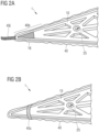
- the base plate can comprise a diamond-shaped outer frame all around, between which a material-saving inner lattice structure with lattice struts for stabilization and stiffening runs or is formed.
- the lattice structure can be designed such that the lattice struts converge in a star shape at three positions on one of the diagonals.
- a middle position of the three positions they can form an overlapping, converging central surface, where the coupling point for a stem is located.
- At least the oblique lattice struts of the lattice structure can protrude from the frame or outer frame at the same angle, so that an overall uniform honeycomb structure is created.
- the lattice struts can be hollow inside to save even more material and weight.
- a single base plate can be designed to detachably attach either another cleaning attachment or a mop textile cover to it.
- a mop textile cover can be detachably attached to the same base plate either via an adhesive element on the base plate and/or via an insertion pocket and a first quick-release element or via a holding plate on the base plate.
- FIG. 1 An embodiment of a cleaning set 1 according to the invention is shown by way of example and schematically in a perspective view of an upper side.
- the main components of this cleaning set 1 include a base plate 10 with a diamond-shaped outline 10g, which has a coupling point 12 for an elongated handle 60 or an end 61 of the handle 60, the optional handle 60 itself and a mop textile cover 40 with a textile base area 40g that is also diamond-shaped and is adapted in shape to the base plate 10.
- the base plate 10 is further constructed from a diamond-shaped outer frame 13, between which a grid structure 14 or grid struts 14 run.
- the grid struts 14 are evenly distributed so that they stabilize the structure evenly.
- the diamond-shaped outline 10g of the base plate 10, or more precisely of the outer frame 13, comprises two acute-angled corner areas 10a, 10b with an interior angle ⁇ ( Figure 4 ) and in between two obtuse-angled corner areas 10c, 10d ( Figure 3 ), which of course lie opposite each other due to the diamond shape.
- the respective acute-angled corner areas 10a, 10b are connected in a stiffening manner by a lattice strut in the longitudinal direction 55L along a long diagonal 57 and the respective obtuse-angled corner areas 10c, 10d are connected in a stiffening manner by a lattice strut in the transverse direction 55Q along a short diagonal 56.
- a lattice strut 14 With Hollow spaces are left in the lattice struts 14, so that the construction requires considerably less material than a base plate made of solid material and above all saves weight.
- the lattice struts 14 themselves are made hollow, which saves material and weight again.
- the lattice struts 14 running diagonally between the diagonals 56, 57 and the outer frame 13 run into the outer frame 13.
- the lattice-like construction or the lattice structure 14 thus saves material and weight, as mentioned, and is also extremely stable.
- the mop textile cover 40 which is explained in more detail below, also has two acute-angled corner areas 40a, 40b with an interior angle ⁇ and two obtuse-angled corner areas 40c, 40d to match the shape or outline 10g of the base plate 10, i.e. its textile base area 40g is adapted to the base plate 10.
- An interior angle ⁇ can preferably be essentially identical to the above-mentioned interior angle ⁇ of the acute-angled corner areas 10a, 10b of the base plate 10, possibly minimally, i.e. a few degrees larger.
- the base plate 10 further comprises an upper side 11 on which the previously mentioned coupling point 12 for the handle 60 is located, more precisely the relevant end 61 of the handle 60 (which is close to the ground when in use).
- an articulated coupling mechanism 90 (see Figure 4 ).
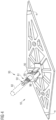
- a part of the coupling mechanism 90 is a fork joint 17 on the base plate 10. This protrudes vertically upwards from the base plate 10 on the upper side 11 and forms with its two parallel "fork tines" or legs, each with a pin, spaced 55L apart in the longitudinal direction (see Figure 5 ) a first fork joint axis 96 or longitudinal axis of rotation 96.
- a joint cube 91 which for this purpose is provided in two side surfaces 91a, 91b facing the legs of the fork joint 17, each with a round bore 92 or a receiving hole 92.
- a pin formed on the inside of each leg of the fork joint 17 is rotatably mounted. This allows the base plate 10 with the fork joint 17 to be rotated about the first fork joint axis 96.
- the coupling mechanism 90 represents a two-axis joint or double joint and thus allows the stem 60 to be pivoted relative to the base plate 10 on an entire "hemispherical surface". That is, the base plate 10 is mounted on the handle 60 or at the end 61 of the handle 60 with sufficient mobility to be able to move it over the floor in any desired wiping motion for cleaning a floor.
- the adapter 93 For coupling with an end 61 of the stem 60, the adapter 93 itself has an adapter element 95 on a side facing away from the fork joint 94, which can be designed for a particular stem type.
- the adapter element 95 comprises Figure 1 and 5 a sleeve with a simple internal thread for solid material handles or handles 60 with a matching external thread at the end 61. These are found mainly in the American region.
- Figure 4 an alternative variant of the adapter element 95' is shown, in which it has a conical fitting section 98 and a conical threaded section 99. These allow coupling with hollow stems or stems 60 that do not have an extra external thread at the end 61. Such stems are particularly common in Europe.
- the base plate 10 has a hook strip 22 as an adhesive element 22, preferably a Velcro element 22, at least in a central area ( Figure 3 ).
- the mop textile cover 40 is in turn attached to this hook strip 22 with a fleece strip 42 as a counter-adhesive element 42, preferably a counter-velcro element 42 ( Figure 1 ).
- a material could be selected for the mop textile cover 40 (at least on the top side 41 or inside 41) which adheres to the hook strip 22.
- the same material can be used for the underside 51 of the mop textile cover 40, i.e. the side of the mop textile cover 40 which comes into contact with the floor to be cleaned during use, provided it is suitable as a cleaning material for the floor.
- the mop textile cover includes 40 in Figure 1
- a first acute-angled corner area 40a of the textile base area 40g on an upper side 41 or inner side 41 there is an insertion pocket 43.
- This consists of an essentially triangular material section which is sewn onto the mop textile cover 40 in the first acute-angled corner area 40a to form a "pocket" so that the first, acute-angled corner area 10a of the base plate 10 can be inserted or threaded into it. This then ensures that the mop textile cover 40 is held particularly securely in position on the base plate 10 in this corner area 10a as well.
- the mop textile cover 40 comprises a first quick-release element 45 on a second acute-angled corner area 40b opposite the first acute-angled corner area 40a of the textile base area 40g, here in the form of an elongated, flexible piece of material 45, in particular in the form of a textile Velcro tab 45l, more precisely a fleece strip 45l, which is fixedly attached to a further hook strip 16 as a counter-coupling element 16 of the base plate 10 on the upper side 11 of the base plate 10 (see Figure 1 ).
- the Velcro tab 45l in the case shown the fleece strip 45l, can be attached to the hook strip 16 of the base plate 10 very quickly, easily and simply in fractions of a second and can be removed again just as quickly.
- two through-holes 25 are formed as parts of second quick-release elements 25 through the base plate 10 from the top side 11 to the bottom side 21.
- the cleaning attachment 70 here for example a brush plate 70
- the cleaning attachment 70 can be attached to the bottom of the base plate 10 in a very simple manner, e.g. by screwing, as a further variant, for example for cleaning a rougher floor covering.
- the brush plate 70 replaces the mop textile cover 40.
- Such a brush plate 70 is also suitable, for example, for particularly stubborn dirt.
- the brush plate 70 is adapted in shape to the base plate 10 and accordingly has a diamond-shaped base area 70g and an upper side 71 with two internally threaded holes 72 and an underside 73 with bristles 74.
- the above-mentioned through holes 25 are therefore used to fasten the brush plate 70 to the base plate 10 using two suitable screw elements 80, here wing screws 80, i.e. threaded rods with wing nuts, so to speak.
- wing screws 80 i.e. threaded rods with wing nuts
- the invention is not limited to such wing screws alone.
- Other comparable screw means or cylindrical clamping or spreading means are also possible, which can be clamped or spread within the through holes.
- the handle 12 ⁇ is arranged on the upper side 11 of the base plate 10 such that a longitudinal direction of the handle 12' runs along the first diagonal from one of the acute-angled corner regions 10a, 10b to the other.
- the axis of the coupling eyelet 12l' then forms a first pivot axis D1, about which the handle can be pivoted relative to the base plate 10.
- a joint mechanism in an adapter that allows pivoting by several degrees of freedom
- the handle bar 12b ⁇ is designed and arranged in such a way that a sufficiently large grip eyelet 12o' remains between the top side 11 of the base plate 10 and the handle bar 12b', into which a user can easily reach with four fingers of his hand.
- the handle bar 12b ⁇ is shaped in such a way that it has several (here specifically four) grip recesses 12g' in order to comfortably place the four fingers on the handle bar 12b ⁇ .
- the arched strut 12a' running above the handle strut 12b' is also shaped in such a way that it allows the handle 12' to be gripped as ergonomically as possible.
- the arched strut 12a' has a slightly curved elongated upper section in the uppermost area and two steeper end sections running at an obtuse angle from it to the top of the base plate 10. These end sections are also only slightly curved.
- a reinforcing bar 10s' runs in the end areas of the longer, first diagonal on the top side 11 of the base plate 10 between the handle strut 12b' and the arched strut 12a' and beyond these into the sharp corner.
- This reinforcing bar 10s' is shaped in such a way that it becomes thinner and lower towards the tip of the base plate 10.
- the entire handle 12' with all struts 12a', 12b', 12c' and the reinforcing bars 10s' is designed in such a way that it is particularly ergonomically shaped and enables working as gently and fatigue-free as possible.
- the base plate 10 due to the lattice construction, it is relatively light and requires only relatively little material, and on the other hand, it is arranged extremely stably on the base plate 10. It is preferably manufactured in one piece with the base plate 10 (particularly preferably using an injection molding process).
- the handle 12' would then be, unlike in Figure 8 shown, preferably not manufactured in a lattice construction, but the area between the handle strut 12b ⁇ and the arched strut 12a' could be filled over its entire surface, ie the handle 12' would then have, for example, a single wide arch (preferably with the grip recesses 12g' on the underside facing the base plate 10).
- the handle strut 12b ⁇ and the arched strut 12a' could have further cross struts to the right and left of the dividing lines.
- This mop textile cover 40 is again designed to match the shape or outline 10g of the base plate 10, i.e. its textile base area is adapted to the base plate 10.
Landscapes
- Engineering & Computer Science (AREA)
- Mechanical Engineering (AREA)
- Cleaning Implements For Floors, Carpets, Furniture, Walls, And The Like (AREA)
Applications Claiming Priority (2)
| Application Number | Priority Date | Filing Date | Title |
|---|---|---|---|
| DE102022111543 | 2022-05-09 | ||
| EP23171965.9A EP4275572A1 (fr) | 2022-05-09 | 2023-05-05 | Ensemble de nettoyage |
Related Parent Applications (1)
| Application Number | Title | Priority Date | Filing Date |
|---|---|---|---|
| EP23171965.9A Division EP4275572A1 (fr) | 2022-05-09 | 2023-05-05 | Ensemble de nettoyage |
Publications (2)
| Publication Number | Publication Date |
|---|---|
| EP4397227A2 true EP4397227A2 (fr) | 2024-07-10 |
| EP4397227A3 EP4397227A3 (fr) | 2024-10-09 |
Family
ID=86330609
Family Applications (2)
| Application Number | Title | Priority Date | Filing Date |
|---|---|---|---|
| EP23171965.9A Pending EP4275572A1 (fr) | 2022-05-09 | 2023-05-05 | Ensemble de nettoyage |
| EP24167447.2A Pending EP4397227A3 (fr) | 2022-05-09 | 2023-05-05 | Ensemble de nettoyage |
Family Applications Before (1)
| Application Number | Title | Priority Date | Filing Date |
|---|---|---|---|
| EP23171965.9A Pending EP4275572A1 (fr) | 2022-05-09 | 2023-05-05 | Ensemble de nettoyage |
Country Status (3)
| Country | Link |
|---|---|
| US (1) | US20240366055A1 (fr) |
| EP (2) | EP4275572A1 (fr) |
| DE (2) | DE202023102462U1 (fr) |
Families Citing this family (2)
| Publication number | Priority date | Publication date | Assignee | Title |
|---|---|---|---|---|
| DE102024108333A1 (de) * | 2024-03-22 | 2025-09-25 | JP Innovations AG | Haltevorrichtung für Wischtuch sowie Wischmopp mit einer solchen |
| US20250302247A1 (en) * | 2024-03-27 | 2025-10-02 | William J. Korek | Windshield washing device |
Citations (1)
| Publication number | Priority date | Publication date | Assignee | Title |
|---|---|---|---|---|
| DE102019113870A1 (de) | 2019-05-23 | 2020-11-26 | André Waldenburger | Adapter zum Befestigen eines Werkzeugs an einem Rohrstiel |
Family Cites Families (9)
| Publication number | Priority date | Publication date | Assignee | Title |
|---|---|---|---|---|
| JPS507963U (fr) * | 1973-05-22 | 1975-01-27 | ||
| US5862565A (en) * | 1997-11-13 | 1999-01-26 | Lundstedt; Kurt | Apparatus for cleaning or scrubbing |
| CA2537584C (fr) * | 2003-09-03 | 2011-11-08 | The Procter & Gamble Company | Dispositif de nettoyage multi-surface |
| JP2005152334A (ja) * | 2003-11-26 | 2005-06-16 | Duskin Co Ltd | ハンディモップ |
| WO2008066771A2 (fr) * | 2006-11-22 | 2008-06-05 | Dinh Minh T | Système de balai-éponge polyvalent et procédé d'utilisation |
| ITPT20090002A1 (it) * | 2009-02-11 | 2010-08-12 | Marco Pinochi | Base o spazzolone per panni da pulizie utilizzabile contemporaneamente da due lati. |
| CN201855231U (zh) * | 2010-05-21 | 2011-06-08 | 孙明丽 | 拖布和与拖布配套使用的刮水器 |
| US20170215686A1 (en) * | 2014-06-17 | 2017-08-03 | Bona AB | Mop head |
| US11998153B2 (en) * | 2019-12-26 | 2024-06-04 | Kenneth Post | Handheld cleaning apparatus |
-
2023
- 2023-05-05 EP EP23171965.9A patent/EP4275572A1/fr active Pending
- 2023-05-05 EP EP24167447.2A patent/EP4397227A3/fr active Pending
- 2023-05-05 DE DE202023102462.9U patent/DE202023102462U1/de active Active
- 2023-05-05 DE DE102023111847.1A patent/DE102023111847A1/de active Pending
-
2024
- 2024-02-01 US US18/429,972 patent/US20240366055A1/en active Pending
Patent Citations (1)
| Publication number | Priority date | Publication date | Assignee | Title |
|---|---|---|---|---|
| DE102019113870A1 (de) | 2019-05-23 | 2020-11-26 | André Waldenburger | Adapter zum Befestigen eines Werkzeugs an einem Rohrstiel |
Also Published As
| Publication number | Publication date |
|---|---|
| US20240366055A1 (en) | 2024-11-07 |
| EP4397227A3 (fr) | 2024-10-09 |
| EP4275572A1 (fr) | 2023-11-15 |
| DE202023102462U1 (de) | 2023-05-15 |
| DE102023111847A1 (de) | 2023-11-09 |
Similar Documents
| Publication | Publication Date | Title |
|---|---|---|
| EP0883369B1 (fr) | Dispositif pour le nettoyage d'objets plats | |
| EP0719107B1 (fr) | Appareil manuel de nettoyage de surfaces lisses | |
| DE29512724U1 (de) | Mophalter sowie Mopbezug hierfür | |
| WO2013131541A1 (fr) | Appareil de nettoyage en mousse synthétique avec surface abrasive | |
| EP4397227A2 (fr) | Ensemble de nettoyage | |
| DE69511373T2 (de) | Bürste mit einem kamm | |
| DE10200033A1 (de) | Wischvorrichtung zum Wischen von zu reinigenden Flächen | |
| DE2611615A1 (de) | Reinigungsgeraet | |
| EP0846438B1 (fr) | Outil pour essuyer un sol humide | |
| DE1503872A1 (de) | Zweischwamm-Handwischgeraet | |
| EP1188406A2 (fr) | Balai à laver | |
| DE2909617C2 (de) | Reinigungsgerät zum Reinigen von Fußböden | |
| WO2005016068A1 (fr) | Balai et adaptateur pour raccorder un element de balai a un manche de balai | |
| DE102012022127A1 (de) | Mopp mit einem Wischbezug | |
| CH354214A (de) | Reinigungsgerät zum Reinigen von Gegenständen, insbesondere von Möbeln, Räumen usw. | |
| DE3926524A1 (de) | Reinigungsgeraet | |
| DE102005012679A1 (de) | Verfahren zum Betreiben eines Flächenreinigungskopfes und Flächenreinigungskopf zur Durchführung des Verfahrens | |
| DE102010013218B4 (de) | Reinigungsgerät | |
| DE19650868C2 (de) | Feuchtbodenwischgerät | |
| DE7608476U1 (de) | Reinigungsgeraet | |
| DE4312522A1 (de) | Hülse zum Aufstecken auf einen Halter eines Reinigungsgeräts, insbesondere für die Teppichreinigung | |
| DE112022007513T5 (de) | Selektiv fixierbarer Wischmopp | |
| DE8909621U1 (de) | Reinigungsgerät | |
| DE102012102803B4 (de) | Tapezierbürste | |
| DE8816777U1 (de) | Handgerät zum Reinigen glatter Flächen, insbesondere Glasscheiben |
Legal Events
| Date | Code | Title | Description |
|---|---|---|---|
| PUAI | Public reference made under article 153(3) epc to a published international application that has entered the european phase |
Free format text: ORIGINAL CODE: 0009012 |
|
| STAA | Information on the status of an ep patent application or granted ep patent |
Free format text: STATUS: THE APPLICATION HAS BEEN PUBLISHED |
|
| AC | Divisional application: reference to earlier application |
Ref document number: 4275572 Country of ref document: EP Kind code of ref document: P |
|
| AK | Designated contracting states |
Kind code of ref document: A2 Designated state(s): AL AT BE BG CH CY CZ DE DK EE ES FI FR GB GR HR HU IE IS IT LI LT LU LV MC ME MK MT NL NO PL PT RO RS SE SI SK SM TR |
|
| PUAL | Search report despatched |
Free format text: ORIGINAL CODE: 0009013 |
|
| AK | Designated contracting states |
Kind code of ref document: A3 Designated state(s): AL AT BE BG CH CY CZ DE DK EE ES FI FR GB GR HR HU IE IS IT LI LT LU LV MC ME MK MT NL NO PL PT RO RS SE SI SK SM TR |
|
| RIC1 | Information provided on ipc code assigned before grant |
Ipc: B25G 1/00 20060101ALI20240903BHEP Ipc: B25G 3/00 20060101ALI20240903BHEP Ipc: A47L 13/25 20060101ALI20240903BHEP Ipc: A47L 13/254 20060101AFI20240903BHEP |
|
| STAA | Information on the status of an ep patent application or granted ep patent |
Free format text: STATUS: REQUEST FOR EXAMINATION WAS MADE |
|
| 17P | Request for examination filed |
Effective date: 20250328 |
|
| STAA | Information on the status of an ep patent application or granted ep patent |
Free format text: STATUS: EXAMINATION IS IN PROGRESS |
|
| 17Q | First examination report despatched |
Effective date: 20250731 |