EP4397238A2 - Vorrichtung zur kontinuierlichen blutzuckermessung - Google Patents
Vorrichtung zur kontinuierlichen blutzuckermessung Download PDFInfo
- Publication number
- EP4397238A2 EP4397238A2 EP24177616.0A EP24177616A EP4397238A2 EP 4397238 A2 EP4397238 A2 EP 4397238A2 EP 24177616 A EP24177616 A EP 24177616A EP 4397238 A2 EP4397238 A2 EP 4397238A2
- Authority
- EP
- European Patent Office
- Prior art keywords
- unit
- sensor
- needle
- housing
- applicator
- Prior art date
- Legal status (The legal status is an assumption and is not a legal conclusion. Google has not performed a legal analysis and makes no representation as to the accuracy of the status listed.)
- Withdrawn
Links
Images












Classifications
-
- A—HUMAN NECESSITIES
- A61—MEDICAL OR VETERINARY SCIENCE; HYGIENE
- A61B—DIAGNOSIS; SURGERY; IDENTIFICATION
- A61B5/00—Measuring for diagnostic purposes; Identification of persons
- A61B5/15—Devices for taking samples of blood
- A61B5/150007—Details
- A61B5/150206—Construction or design features not otherwise provided for; manufacturing or production; packages; sterilisation of piercing element, piercing device or sampling device
-
- A—HUMAN NECESSITIES
- A61—MEDICAL OR VETERINARY SCIENCE; HYGIENE
- A61B—DIAGNOSIS; SURGERY; IDENTIFICATION
- A61B5/00—Measuring for diagnostic purposes; Identification of persons
- A61B5/0002—Remote monitoring of patients using telemetry, e.g. transmission of vital signals via a communication network
- A61B5/0015—Remote monitoring of patients using telemetry, e.g. transmission of vital signals via a communication network characterised by features of the telemetry system
- A61B5/0024—Remote monitoring of patients using telemetry, e.g. transmission of vital signals via a communication network characterised by features of the telemetry system for multiple sensor units attached to the patient, e.g. using a body or personal area network
-
- A—HUMAN NECESSITIES
- A61—MEDICAL OR VETERINARY SCIENCE; HYGIENE
- A61B—DIAGNOSIS; SURGERY; IDENTIFICATION
- A61B5/00—Measuring for diagnostic purposes; Identification of persons
- A61B5/145—Measuring characteristics of blood in vivo, e.g. gas concentration or pH-value ; Measuring characteristics of body fluids or tissues, e.g. interstitial fluid or cerebral tissue
- A61B5/14532—Measuring characteristics of blood in vivo, e.g. gas concentration or pH-value ; Measuring characteristics of body fluids or tissues, e.g. interstitial fluid or cerebral tissue for measuring glucose, e.g. by tissue impedance measurement
-
- A—HUMAN NECESSITIES
- A61—MEDICAL OR VETERINARY SCIENCE; HYGIENE
- A61B—DIAGNOSIS; SURGERY; IDENTIFICATION
- A61B5/00—Measuring for diagnostic purposes; Identification of persons
- A61B5/15—Devices for taking samples of blood
- A61B5/150007—Details
- A61B5/150374—Details of piercing elements or protective means for preventing accidental injuries by such piercing elements
- A61B5/150381—Design of piercing elements
- A61B5/150389—Hollow piercing elements, e.g. canulas, needles, for piercing the skin
-
- A—HUMAN NECESSITIES
- A61—MEDICAL OR VETERINARY SCIENCE; HYGIENE
- A61B—DIAGNOSIS; SURGERY; IDENTIFICATION
- A61B5/00—Measuring for diagnostic purposes; Identification of persons
- A61B5/15—Devices for taking samples of blood
- A61B5/151—Devices specially adapted for taking samples of capillary blood, e.g. by lancets, needles or blades
- A61B5/15101—Details
- A61B5/15103—Piercing procedure
- A61B5/15107—Piercing being assisted by a triggering mechanism
- A61B5/15113—Manually triggered, i.e. the triggering requires a deliberate action by the user such as pressing a drive button
-
- A—HUMAN NECESSITIES
- A61—MEDICAL OR VETERINARY SCIENCE; HYGIENE
- A61B—DIAGNOSIS; SURGERY; IDENTIFICATION
- A61B5/00—Measuring for diagnostic purposes; Identification of persons
- A61B5/15—Devices for taking samples of blood
- A61B5/151—Devices specially adapted for taking samples of capillary blood, e.g. by lancets, needles or blades
- A61B5/15186—Devices loaded with a single lancet, i.e. a single lancet with or without a casing is loaded into a reusable drive device and then discarded after use; drive devices reloadable for multiple use
- A61B5/15188—Constructional features of reusable driving devices
- A61B5/1519—Constructional features of reusable driving devices comprising driving means, e.g. a spring, for propelling the piercing unit
-
- A—HUMAN NECESSITIES
- A61—MEDICAL OR VETERINARY SCIENCE; HYGIENE
- A61B—DIAGNOSIS; SURGERY; IDENTIFICATION
- A61B5/00—Measuring for diagnostic purposes; Identification of persons
- A61B5/68—Arrangements of detecting, measuring or recording means, e.g. sensors, in relation to patient
- A61B5/6846—Arrangements of detecting, measuring or recording means, e.g. sensors, in relation to patient specially adapted to be brought in contact with an internal body part, i.e. invasive
-
- A—HUMAN NECESSITIES
- A61—MEDICAL OR VETERINARY SCIENCE; HYGIENE
- A61B—DIAGNOSIS; SURGERY; IDENTIFICATION
- A61B5/00—Measuring for diagnostic purposes; Identification of persons
- A61B5/68—Arrangements of detecting, measuring or recording means, e.g. sensors, in relation to patient
- A61B5/6846—Arrangements of detecting, measuring or recording means, e.g. sensors, in relation to patient specially adapted to be brought in contact with an internal body part, i.e. invasive
- A61B5/6847—Arrangements of detecting, measuring or recording means, e.g. sensors, in relation to patient specially adapted to be brought in contact with an internal body part, i.e. invasive mounted on an invasive device
- A61B5/6848—Needles
-
- A—HUMAN NECESSITIES
- A61—MEDICAL OR VETERINARY SCIENCE; HYGIENE
- A61B—DIAGNOSIS; SURGERY; IDENTIFICATION
- A61B2560/00—Constructional details of operational features of apparatus; Accessories for medical measuring apparatus
- A61B2560/06—Accessories for medical measuring apparatus
- A61B2560/063—Devices specially adapted for delivering implantable medical measuring apparatus
Definitions
- the present disclosure is related to an apparatus for continuously measuring blood glucose.
- the present disclosure is related to a continuous blood glucose measurement apparatus in which, by manufacturing the continuous blood glucose measurement apparatus in a state that the body attachable unit is assembled in an applicator, the body attachable unit can be attached to a human body by simply operating the applicator by minimizing additional work of a user for attaching the body attachable unit to the human body, specially, by including a wireless communication chip in the body attachable unit in order to provide telecommunication with an external terminal, it is possible that the use can be more simple and convenient without additional work for connecting a separate transmitter and the maintenance can also be more easily performed, and by initiating the operation according to the manipulation of the user after the body attachable unit is attached to the human body, the operation start time can be adjusted to a proper time depending on the need of the user, the operation can be started in a stable status and more precise blood glucose measurement can be provided.
- Diabetes is a chronic medical condition that is common in modern people, and in the Republic of Korea, there are 2 million diabetes patients, about 5% of the total population.
- Diabetes occurs when the absolute level of the sugar level in blood is high due to the absolute deficiency or relative insufficiency of insulin, produced by the pancreas, caused by various reasons such as obesity, stress, poor eating habits, and inherited hereditary factors and imbalance regarding glucose in the blood.
- the blood usually contains a certain concentration of glucose, and tissue cells gain energy from the glucose.
- Diabetes is characterized by substantial absence of subjective symptoms at the beginning of the condition, when diabetes progresses, diabetes-specific symptoms such as overdrink, overeat, polyuria, weight loss, weariness, skin itchiness, and lower ability of naturally healing on injury on hands and feet are shown, and further progression of diabetes leads to complications such as visual disturbances, hypertension, kidney disease, paralysis, periodontal disease, muscle spasms and neuralgia, as well as gangrene.
- diabetes-specific symptoms such as overdrink, overeat, polyuria, weight loss, weariness, skin itchiness, and lower ability of naturally healing on injury on hands and feet are shown, and further progression of diabetes leads to complications such as visual disturbances, hypertension, kidney disease, paralysis, periodontal disease, muscle spasms and neuralgia, as well as gangrene.
- Glucose measuring devices may be categorized into a single time measurement type measuring a blood glucose level and collecting blood from a fingertip by a user every single time and a continuous measurement type attaching a glucose monitoring system to the belly or an arm of the user and continuously measuring blood glucose levels.
- Diabetics patients generally experience hyperglycemia and hypoglycemia, an emergency may occur in the hypoglycemic conditions, and the patients may become unconscious or die if a hypoglycemic condition lasts for an extended period of time without the supply of sugar. Accordingly, although rapid discovery of the hypoglycemic condition is critically important for diabetics, blood-collecting type glucose monitoring devices intermittently measuring glucose have limited ability to accurately measure blood glucose levels.
- continuous glucose monitoring systems are manufactured to have a wide variety of types depending on their manufacturers, and are used in a variety of methods. However, the most of the continuous glucose monitoring systems are manufactured and distributed as a type that a one-time use sensor module is attached to the human body using an applicator, the user should perform multistage operations/manipulation to operate the applicator to attach the one-time use sensor module to the human body, and after the sensor module is attached to the human body, the user should perform various follow-up operations, such as a procedure of withdrawing a needle by the user.
- the main case may comprise an outer case, wherein the pressure button is installed to one side of the outer case, and an inner case coupled to an inside of the outer case, the inner case configured to guide a linear movement path of the plunger body.
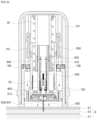
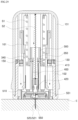
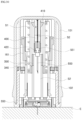
- the body attachable unit (20) is assembled and produced in a state that the body attachable unit (20) is inserted into the inside of the applicator (10), and is configured to move in an outward discharge direction pursuant to the operation of the applicator (10) by the manipulation of the user and be attached to the human body.
- an adhesive tape (560) is provided at a side of the body attachable unit (20) contacting the human body to be attached to the body, to protect the adhesive tape (560) a release paper (561) is attached to a surface of the adhesive tape (560) contacting the human body, and the release paper (561) of the adhesive tape (560) may be configured to be separated and removed from the adhesive tape (560) during the operation of separating the protection cap (200) from the applicator (10).
- the applicator (10) fixes the body the attachable unit (20), and in a state that the body attachable unit (20) is outwardly discharged and moved, the applicator (10) is configured to release the fixed state of the body attachable unit (20).
- the needle unit (550) may be separatably coupled to the housing (510) in a direction penetrating the top and bottom of the housing (510) of the body attachable unit (20), the needle unit (550) may be formed to have a structure covering the outside of the sensor unit (520), and a need head (551) is formed at the upper end portion of the needle unit (550). If the body attachable unit (20) is moved in the direction outwardly discharged by the applicator (10), the needle unit (550) is inserted into the human body first before the sensor unit (520) is inserted into the human body and the needle unit (550) may support the sensor unit (520) such that the sensor unit (520) can be stably inserted in the skin.
- the protection cap (200) as a separate element may be separatably coupled to the lower end portion of the main case (100) to protect the inside of the body attachable unit (20).
- the release paper (560) may be applied to the upper surface of the inner side supporting unit (203) of the protection cap (200), and may be attached to the inner side supporting unit (203) of the protection cap (200) through separate adhesive material (562). Accordingly, as illustrated in FIG. 7 , the separate adhesive material (562) is adhered to one side of the lower surface of the release paper (561), and this adhesive material (562) is disposed between the upper surface of the inner side supporting unit (203) of the protection cap (200) and the release paper (561) and the lower surface of the adhesive material (562) is adhered to the upper surface of the inner side supporting unit (203).
- the adhesive strength of the adhesive material (562) may be greater than the adhesive strength between the release paper (561) and the adhesive tape (560).
- the release paper (561) adhered to the inner side supporting unit (203) of the protection cap (200) is also separated together with the protection cap (200) through the adhesive material (562) and separated and removed from the adhesive tape (560).
- the pressure button (110) is installed to be configured to provide mode change between a safe mode blocking the pressure movement performed according to the pressure operation and a pressure standby mode capable of performing the pressure movement performed according to the pressure operation.
- the pressure button (11) may be configured to, in a safe mode state, slidingly move along an exterior surface of the main case (100) for a certain section to change to a standby mode state.
- a hanging raised part (1012) is formed at a portion of the main case (100) where the pressure button (110) is coupled, in the safe mode state, the pressure button (110) is interlocked with the hanging raised part (1012) to block the pressuring movement, and as the sliding movement is from the safe mode state to the pressure standby mode state performed, the interlock from the hanging raised part (1012) is released to make the pressuring movement possible.
- the pressure button (110) in the safe mode state, the pressure button (110) is interlocked at the hanging raised part (1012) of the outer case (101) so that the pressurizing operation cannot be performed, and as illustrated in FIG. 11 , when the pressure button (110) is upwardly moved to the pressure standby mode state, the interlock with the hanging raised part (1012) of the outer case (101) is released and it is possible to perform the pressurizing operation.
- the position of the pressure button (110) may be fixed not to return to the safe mode state.
- a fixing protrusion (114) is formed at one side of the pressure button (110), a transformable cut portion (1013) is formed at the bottom surface of the button guide groove (1011) of the outer case (101) and in a structure that a certain section is cut to be elastically transformable, the transformable cut portion (1013) comprises a receivable groove (1014) configured to be insertedly receive the fixing protrusion (114) when the pressure button (110) is positioned at the safe mode, and in a state that the movement of the pressure button (110) to the pressure standby mode is completed, an end portion of the pressure button (110) is interlocked with the fixing protrusion (114) to block the returning movement of the pressure button (110).
- the pressure button (110) can perform pressurizing operation by manipulated by the user only in a state that it is slidingly moved to the pressure standard mode state, and therefore the pressure operation caused by the user's mistake can be prevented and it is possible to use safely.
- the pressure button (110) is changed to the pressure standby mode state and the pressurizing operation is performed as shown in FIG. 12 , the pressure button (110) the pressure rod (111) of the pressure button (110) applies pressure to and moves the shooting plate (150).
- the shooting plate (150) is supported in the inner case (102) and slidably movably coupled according to the pressurizing operation of the pressure button (110), and the plunger body (300) is interlocked with the shooting plate (150) at the first location and according to the movement of the shooting plate (150) the interlock with the shooting plate (150) is released and the plunger body (300) is moved to the second location by the elastic force of the plunger elastic spring (S1).
- An interlock hook (310) is formed at the plunger body (300) to interlock with the shooting plate (150) as illustrated in FIGS. 12 and 13 , the hanging protrusion part (153) interlockable with the interlock hook (310) of the plunger body (300) is formed at one side of the shooting plate (150), and the hanging protrusion part (153) may be configured to be released from the state interlocking with the interlock hook (310) as the shooting plate (150) is slidingly moved.
- the guide rail (162) is formed to protrude to guide the slide movement path of the shooting plate (150), and the guide slot (151) is formed at the shooting plate (150) to insertedly guide the guide rail (162).
- an elastic structure (163) elastically supporting the shooting plate (150) in a direction opposite to a slide movement direction by the operation of the pressure button (110) is installed at the inner case (102). Accordingly, the shooting plate (150) is elastically supported by the pressure button (110) by the elastic force of the elastic structure (163), and therefore unless the pressure button (110) is manipulated for pressurization, the interlocking status of the plunger body (300) with the interlock hook (310) can be stably maintained.
- the shooting plate (150) when the user operates to pressurize the pressure button (110), the shooting plate (150) is slidingly moved, and this may result in releasing the interlocked state of the plunger body (300) and the shooting plate (150) and the plunger body (300) is outwardly discharged from the first location to the second location as shown in FIGS. 15 and 16 .
- a stopper protrusion (320) may be formed at the plunger body (300) to limit a range movable to the second location, and as the plunger body (300) is moved to the second location, the stopper protrusion (320) can limit the movement of the plunger body (300) by a way of being interlocked with one side of the inner case (102). Accordingly, the plunger body (300) can be moved up to the second location by the stopper protrusion (320), and the plunger body (300) cannot be outwardly discharged from the main case (100) over that range.
- the plunger body (300) is interlocked with the stopper protrusion (320) in a state that the plunger body (300) is moved to the second location and a stopper fixing unit (1021) may be formed to limit the movement of the stopper protrusion (320).
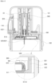
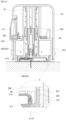
- a sensor receiving unit (301) is formed at one end portion of the plunger body (300) so that the body attachable unit (20) is insertedly received, and the body attachable unit (20) is insertedly received by the sensor receiving unit (301) and linearly move together with the plunger body (300) from the first location to the second location. As the plunger body (300) and the body attachable unit (20) are linearly moved to the second location, the sensor probe (512) and the needle unit (550) of the body attachable unit (20) are inserted into the human body.
- a sensor fixing hook (330) fixedly coupling the body attachable unit (20) by being interlockedly coupled with the body attachable unit (20) inserted to the sensor receiving unit (301) is installed at an edge of the sensor receiving unit (301).
- An interlock coupling groove (5112) is formed at both end portions of the body attachable unit (20) to be interlocked with the sensor fixing hook (330) in a state that the body attachable unit (20) is inserted into the sensor receiving unit (301).
- a hook guide unit (not shown) is formed on the inner surface of the inner case (102) and the hook guide unit pressurizes the sensor fixing hook (330) in an inward direction to be interlocked with the body attachable unit (20) and has a cross-sectional shape having a structure that the sensor fixing hook (330) is released from the pressurization in the state of the plunger body (300) moved to the second location.
- the hook guide unit may have a structure with convex and concave surfaces on the inner surface of the inner case (102), the convex surface applies pressure to the sensor fixing hook (330) and the concave surface releases the sensor fixing hook (330) from the pressure application, and the concave is formed to release the sensor fixing hook (330) from the pressure application in a state that the sensor fixing hook (330) is moved together with the plunger body (300) to the second location.
- the embodiment of the present disclosure is manufactured in a state that the body attachable unit (20) is inserted in the applicator (10), the reuse of the body attachable unit (20) by inserting again another body attachable unit (20) to the applicator (10) may be prevented as described above.
- the return prevention means may be configured to comprise a interlocking body (340) formed on one side of the plunger body (300), and a return prevention hook (161) formed at the inner case (102) and configured to prevent the returning movement of the plunger body (300) by being interlockedly coupled with the interlocking body (340) of the plunger body (300) when the downward movement of the plunger body (300) from the fist location to the second location is completed.
- the return prevention hook (161) is configured to be interlocked with the interlocking body (340) by elastic restoring force in the operation of be interlocked with the interlocking body (340).
- the return prevention hook (161) may be configured to have a structure comprising a rotatable body (1611) elastically rotatably coupled around a rotary shaft (1613) and at one side of the inner case (102), and a hook body (1612) slantly protruding from the inner side surface of the rotatable body (1611) in a downward and inward direction.
- the rotary axis (1613) is configured to elastically support the rotatable body (1611) in a inward and protruding direction of the hook body (1612) by applying elastic force according to a material character of elastic material.
- the state of the operation of the return prevention hook (161) will be described in detail, and if the plunger body (300) is moved to the second location by the operation of the pressure button (110) in a state that the plunger body (300) is positioned at the first location as shown in FIG. 17 , the hook body (1612) is pressurized by the interlocking body (340) of the plunger body (200) during the movement of the plunger body (300) to the second location as illustrated in FIG. 18 , and then the return prevention hook (161) is elastically rotated in a clockwise direction (an outward direction) around the rotary axis (1613). After that, if the movement of the plunger body (300) to the second location is completed as shown in FIG.
- the return prevention hook (161) is returned by being elastically rotated around the rotary shaft (1613) in a count-clockwise direction (an inward direction). Likewise, as the return prevention hook (161) is elastically return-rotated, the lower portion of the return prevention hook (161) is interlocked with the upper portion of the interlocking body (340) of the plunger body (300), and therefore the returning movement of the plunger body (300) to the first location in a state interlocking with the return prevention hook (161) and the interlocking body (340) is prevented.
- the applicator (10) is configured to extract and remove the needle unit (550) of the body attachable unit (20) from the human body at a time of the completion of outward discharge movement of the body attachable unit (20) from the first location to the second location
- the applicator (10) may comprise a needle extracting means (N) configured to upwardly move the needle unit (550) and extract and remove the needle unit (550) from the human body at a time of the completion of the movement of the plunger body (300) from the first location to the second location.
- the needle extracting means (N) may comprise a needle extracting body (400) coupled with the needle head (551) of the needle unit (550) and linearly move along the inner case (102) from the first location to the second location together with the plunger body (300) by being interlocked with the plunger body (300), and a needle extracting elastic spring (S2) applying elastic force to the needle extracting body (400) in a direction that the needle extracting body (400) upwardly moves toward the first location.
- a needle extracting body (400) coupled with the needle head (551) of the needle unit (550) and linearly move along the inner case (102) from the first location to the second location together with the plunger body (300) by being interlocked with the plunger body (300), and a needle extracting elastic spring (S2) applying elastic force to the needle extracting body (400) in a direction that the needle extracting body (400) upwardly moves toward the first location.
- the needle extracting body (400) is interlockedly coupled to the plunger body (300), and for this purpose, a separate elastic hook (410) configured to be elastically transformable is provided at the needle discharge body (400), and the elastic hook (410) is elastically biased in a direction interlockedly coupled to the hook interlocking unit (350) of the plunger body (300). Accordingly, if the plunger body (300) is linearly moved from the first location to the second location according to the operation of the pressure button (110), the needle extracting body (400) is also linearly moved to the second location together with the plunger body (300).
- a needle extracting pressurizing unit (130) configured to pressurize the elastic hook (410) in an inward direction so that the elastic hook (410) is released from the interlock with the hook interlocking unit (350) of the plunger body (300) according to the movement of the needle extracting body (400) to the second location is included in the inner case (102).
- the needle extracting body (400) linearly moves from the first location to the second location together with the plunger body (300) as illustrated in FIG. 19 , at the same time the elastic hook (410) of the needle extracting body (400) is pressurized by the needle extracting pressurizing unit (130) and is released from the state interlocked with the hook interlocking unit (350), and therefore the needle extracting body (400) is upwardly return-moved toward the first location by the elastic force of the needle extracting elastic spring (S2) as shown in FIG. 20 .
- the needle extracting body (400) is coupled with the needle head (551) of the needle unit (550) through an end of a needle head coupling unit (420), during the operation that the needle extracting body (400) is upwardly return-moved, the needle unit (550) is moved together and removed from the human body.
- the needle head coupling unit (420) is formed at the lower end portion of the needle extracting body (400) by a form of being interlockedly coupled to the coupling groove (552) formed at the needle head (551).
- the sensor probe (521) and the needle unit (550) of the body attachable unit (20) is inserted into the human body, but the needle unit (550) may be slightly retracted in a direction opposite to a human body insertion direction by reaction force generated by insertion resistance during the process of inserting the needle unit (550) to the human body.
- the sensor probe (521) is not inserted into the human body to a proper depth, the retraction of the needle unit (550) needs to be prevented.
- a needle supporting block may be coupled to the needle attachable body (400), and the needle supporting block is configured to downwardly support an upper end of the needle unit (550) so that the needle unit (550) cannot be upwardly moved with respect to the needle extracting body (400).
- FIGS. 21 to 25 are views illustrating use states of a continuous blood glucose measurement apparatus according to operation order step by step according to an embodiment of the present disclosure.
- the protection cap (200) of the applicator (10) is separated.
- the release paper (561) of the adhesive tape (560) of the body attachable unit (20) is separated together with the protection cap (200) and removed from the adhesive tape (560).
- the sensor applicator assembly is located on a position of the human body to attach the body attachable unit (20), and in this state, after changing a mode of the pressure button (110) from the safe mode to the pressurization standby mode, the pressure button (110) is operated to be pressurized.
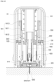
- the state interlocking with the plunger body (300) is released by the movement of the shooting plate (150), therefore the plunger body (300) is downwardly moved in a direction outwardly discharged by the plunger elastic spring (S 1) as illustrated in FIGS. 22 and 23 , and in this process, the needle unit (550) and the sensor probe (521) of the body attachable unit (20) is inserted into the human body (E). In this time, the body attachable unit (20) is adhered to a surface of the human body (E) by the bottom surface of the adhesive tape (560).
- the sensor fixing hook (330) of the sensor receiving unit (301) can be received from a state interlockedly coupled with the body attachable unit (20) as illustrated in FIG. 23 . Additionally, the elastic hook (410) of the needle extracting body (400) is pressurized in an inward direction by the needle extracting pressurizing unit (130) of the inner case (102) and the state interlocked with the plunger body (300) is released.
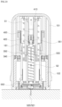
- the needle extracting body (400) is upwardly return-moved by the needle extracting elastic spring (S2) as illustrated in FIG. 24 .
- the needle unit (550) is extracted and removed from the human body (E).
- the applicator (10) can be upwardly separated and removed as shown in FIG. 25 , and if the applicator (10) is separated and removed in this way, only the body attachable unit remains in the state attached to the human body (E).
- the sensor unit (520) and the wireless communication chip (540) of the body attachable unit (20) can initiate operation by the operation of a pressurizing operation module (570) of the body attachable unit (20) and so on, and therefore the measurement result of the blood glucose by the body attachable unit (20) can be transmitted to a separate external terminal.
- a pressurizing operation module (570) of the body attachable unit (20) can be transmitted to a separate external terminal.
- the wireless communication chip (540) are installed to the body attachable unit (20), no additional work for connecting and coupling a separate transmitter is needed.
- the plunger body (300) is outwardly discharged from the first location in the main case (100) to the second location outside the main case (100), and in this operation, the body attachable unit (20) is moved together with the plunger body (300) and the needle unit (550) and the sensor unit (520) is inserted into the human body (E).
- the elastic hook (410) is pressurized by the needle extracting pressurizing unit (130) as illustrated in FIG. 26 and the elastic hook (410) is released from the interlock with the plunger body (300), and in this state the needle extracting body (400) is upwardly return-moved by the elastic force of the needle extracting elastic spring (S2) toward the first location as shown in FIG. 27 .
- the needle extracting elastic spring (S2) for return-moving the needle extracting body (400) toward the first location of the inside of the main case (100) is illustrated as a compression type spring, a tension type spring can be used instead as illustrated in FIGS. 28 to 30 .
- the compression-type needle extracting elastic spring (S2) have both ends which are coupled to the plunger body (300) and the needle extracting body (400), and is arranged in a compressed form and is configured to return-move the needle extracting body (400) toward the first location by tension restoration elastic force.
- FIG. 31 is a perspective view conceptually illustrating an outer structure of a body attachable unit attached to a human body according to an embodiment of the present disclosure
- FIG. 32 is an exploded perspective view conceptually illustrating components of a body attachable unit
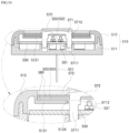
- FIG. 33 is a cross-sectional view taken along line "C-C" of FIG. 31
- FIG. 34 is a cross-sectional view taken along line "D-D” of FIG. 31
- FIG. 35 is a conceptual view illustrating a operation state of a pressurizing operation module according to an embodiment of the present disclosure.
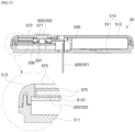
- the electrical contact point (531) is formed at the PCB board (530) to be electrically connected with the sensor unit (520), and the wireless communication chip (540) is installed to the PCB board (530) to transmit the glucose measurement result measured by the sensor unit (520) to an external terminal.
- the wireless communication chip (540) is installed at the inside of the body attachable unit (20) to transmit the glucose measurement result measured by the sensor unit (520) to an external terminal.
- the body attachable unit (20) is formed so that the other end portion of the sensor unit (520), i.e., the sensor body unit (522), is contacted to the electrical contact point (531) of the PCB board (530) by the manipulation or operation of the user, and according to this electrical contact, the operation of the body attachable unit (20) may be initiated.
- the embodiment of the present embodiment is configured to perform the power supply as well as the initiation of the operation of the sensor unit (520), the wireless communication chip (540) and other components by the electrical connection of the sensor unit (520) and the PCB board (530) by the manipulation of the user.
- the pressurizing operation module (570) is movably connected to the housing (510) and may comprise a movable pressurizing body (571) configured to be movable in a pressurizing direction by the pressure applied by the user, and according to the movement of the movable pressurizing body (571) at least a partial area of the other end portion of the sensor unit (520) is transformed by the pressure of the movable pressurizing body (571) and contacted to the electrical contact point (531) of the PCB board (530).
- a movable pressurizing body (571) configured to be movable in a pressurizing direction by the pressure applied by the user, and according to the movement of the movable pressurizing body (571) at least a partial area of the other end portion of the sensor unit (520) is transformed by the pressure of the movable pressurizing body (571) and contacted to the electrical contact point (531) of the PCB board (530).
- the seal processing means at the coupling portion between the button cover (572) and the housing (510) may be configured to use a double-side tape (580).
- a double-side tape (580) For example, one side of the double-side tape (580) is adhered to the other portion of the sensor unit (520), such as one side of the sensor body unit (522), along its circumferential edge, the other side of the double-side tape (580) is adhered to the inner-side surface of the button cover (572) along its circumferential edge, and this double-side tape (580) can seal the circumferential edge of the button cover (572).
- the movable pressurizing body (571) is moved in the pressurized direction, because the button cover (572) is made of flexible material and the circumferential edge portion of the button cover (572) is adhered to the housing (510) by the double-side tape (580), only the center portion of the button cover (572) is transformed in the pressurized direction and the circumferential edge portion of the button cover (572) is adheredly fixed and remains the sealed state.
- the contact status can be stably maintained for stable measurement of blood glucose, and for this, the movable pressurizing body (571) is formed to be fixedly positioned in a state that the movable pressurizing body (571) is moved in a pressurized direction by the urging force.
- a protruding guide unit (5711) protruding along a movement direction of the movable pressurizing body (571) is formed at the movable pressurizing body (571) as illustrated in FIG. 36 , and a locking hook (5712) may be formed at the outer circumferential surface of the protruding guide (5711).
- an interlocking projection (5124) to which the locking hook (5712) of the protruding guide unit (5711) in a state that the movable pressurizing body (571) is moved in the pressurized direction may be formed at the housing (510).
- the position of the movable pressurizing body (571) may be fixed as the locking hook (5712) is interlockedly coupled to the interlocking projection (5124) as shown in FIG. 35 .
- the interlocking projection (5124) may be formed at the sensor supporting unit (5121) of the housing (510), at least two guide fixing units (5123) separated to each other, formed along a circumferential direction and having a structure covering the protruding guide unit (5711) of the movable pressurizing body (571) are formed at the sensor supporting unit (5121) of the housing (510) as illustrated in FIG. 36 , and the interlocking protrusion (5124) may be formed at each guide fixing unit (5123). Additionally, each guide fixing unit (5123) may be arranged in a structure being elastically supported by the elastic supporting unit (5125) which is configured to be elastically transformable.
- the guide fixing unit (5123) is elastically transformed and makes the movement of the movable pressurizing body (571) smooth
- the guide fixing unit (5123) is elastically returned and the locking hook (5712) is interlockedly coupled to the interlocking projection (5124), and because the guide fixing unit (5123) is elastically supported by the elastic supporting unit (5125), the interlocking coupling state between the locking hook (5712) and the interlocking projection (5124) is stably maintained.
- the pressure transforming unit (523) further comprise a second cut section (5233) positioned at the center section of the sensor body unit (522) and having a structure cut along a second cut line (5234) formed at the outer section of the first cut line (5232), and the first cut area (5231) and the second cut area (5233) may be formed to be transformable by the pressure applied by the movable pressurizing body (571).
- a first cut section (5231) of the pressure transforming unit (523) is downwardly elastically transformed as illustrated in FIGS. 38 (a) and (b)
- a second cut section (5233) formed at an outer section of the first cut are (5231) is downwardly elastically transformed sequentially, and therefore because the first cut section (5231) directly contacting the electric contact point (531) of the PCB board (530) contact the electric contact point (531) of the PCB board (530) in a relatively horizontal state, the contacting state to the electric contact point (531) of the sensor body unit (522) can be more stably maintained.
- a plurality of electric contact points (531) electrically contacting the sensor body unit (522) may protrude toward the sensor body unit (522), and the protruding height of at least one of the plurality of electric contact points (531) may be higher than the rest.
- the protruding height of one of the electric contact points (531) is formed be higher than the other of the electric contact points (531), and therefore clearance distances d1, d2 are formed differently from each other.
- the sensor body unit (522) of the senor unit (520) and the electric contact point (531) of the PCB board are disposed to be separated from each other, but can contact each other by the pressure operation of the user.
- the housing (531) may be formed in a very thin structure, it may be difficult of stably maintaining the separation state between the sensor body unit (522) and the electric contact point (531) in the housing (510).
- the sensor body unit (522) and the electric contact point (531) may be manufactured and distributed to customers in a state that the sensor body unit (522) and the electric contact point (531) contact each other by the manufacture and assembly tolerance and other reasons before the pressure operation of the user.
- the protruding height of at least one of the plurality of electric contact points (531) is higher that the rest of the electric contact points (531) as described above, only the electric contact point (531) having the highest protruding height may contact the sensor body unit (522) and the other electric contact points (531) may maintain a separation state from the sensor body nit (522). This is because the highest protruding contact point (531) can perform the function of upwardly supporting the sensor body unit (522).
- the plurality of electric contact points (531) may be configured to elastically transformable and be formed to elastically protruding from the PCB board (530), and such an elastic force may perform the desired function of support and contact associated with the sensor body unit (522).
- the operation of the body attachable unit (20) is not initiated. Accordingly, the operation of the sensor unit (520), the wireless communication chip (540), and other components is not initiated, and the power supply by the battery (535) may not be initiated.
- This operation initiation prevention function can result from simple means for setting the circuit pattern of the PCB board (530) to be activated only when all of the plurality of the electric contact points (531) contact the sensor body unit (522).
- the pressurizing operation module (570) may need to be formed so that the movement distance of the movable pressurizing body (571) can be greater than the separation distance between the lowest protruding electric contact point (531) among the plurality of the electric contact points (531) and the sensor body unit (522).
- FIGS. 40 to 42 are conceptual views of various configuration of a contact point connection module according to embodiments of the present disclosure.
- a contact point connection module (590) which is operated by the manipulation of the user so that the sensor body unit (522) and the electric contact point (531) of the PCB board (530) contact each other is illustrated in FIGS. 40 to 42 , and this contact point connection module (590) may be configured to operate in a type that in a state that the contact point connection module (590) is positioned between the sensor body unit (522) and the electric contact point (531) of the PCB board (530) to block their contact the contact point connection module (590) may be moved by the operation of the user to release from blocking the contact between the sensor body unit (522) and the electric contact point (531) of the PCB board (530).
- the electric contact point (531) of the PCB board (530) is formed to elastically protrude in a direction that the electric contact point (531) can contact the sensor body unit (522), and as the contact point connection module (590) releases from blocking the contact between the sensor body unit (522) and the electric contact point (531) of the PCB board (530), the electric contact point (531) of the PCB board (530) is configured to be elastically moved by the elastic force and be contacted to the other end portion of the sensor unit (520).
- the movable plate (591) As shown in FIG. 40(a) , in the assembled state that the movable plate (591) is inserted into the inside of the housing (510), the movable plate (591) is positioned between the sensor body unit (522) and the electric contact point (531) to block the contact between the sensor body unit (522) and the electric contact point (531), and as illustrated in FIG. 40(b) , if the movable plate (591) is moved in a direction of being discharged and removed from the housing (510) by the operation of the user, the electric contact point (531) is upwardly moved by the elastic force and contacted to the sensor body unit (522).
- a stopper unit (592) formed to limit a movable range of the movable plate (591) to between the first location and the second location may be formed at the movable plate (591).
Landscapes
- Health & Medical Sciences (AREA)
- Life Sciences & Earth Sciences (AREA)
- Physics & Mathematics (AREA)
- Engineering & Computer Science (AREA)
- Surgery (AREA)
- Public Health (AREA)
- Biomedical Technology (AREA)
- Heart & Thoracic Surgery (AREA)
- Medical Informatics (AREA)
- Molecular Biology (AREA)
- Biophysics (AREA)
- Animal Behavior & Ethology (AREA)
- General Health & Medical Sciences (AREA)
- Pathology (AREA)
- Veterinary Medicine (AREA)
- Hematology (AREA)
- Emergency Medicine (AREA)
- Optics & Photonics (AREA)
- Manufacturing & Machinery (AREA)
- Computer Networks & Wireless Communication (AREA)
- Measurement Of The Respiration, Hearing Ability, Form, And Blood Characteristics Of Living Organisms (AREA)
Applications Claiming Priority (3)
| Application Number | Priority Date | Filing Date | Title |
|---|---|---|---|
| KR1020180089339A KR102222045B1 (ko) | 2018-07-31 | 2018-07-31 | 연속 혈당 측정 장치 |
| PCT/KR2019/006840 WO2020027423A1 (ko) | 2018-07-31 | 2019-06-07 | 연속 혈당 측정 장치 |
| EP19844623.9A EP3831298B1 (de) | 2018-07-31 | 2019-06-07 | Vorrichtung zur kontinuierlichen blutzuckermessung |
Related Parent Applications (2)
| Application Number | Title | Priority Date | Filing Date |
|---|---|---|---|
| EP19844623.9A Division EP3831298B1 (de) | 2018-07-31 | 2019-06-07 | Vorrichtung zur kontinuierlichen blutzuckermessung |
| EP19844623.9A Division-Into EP3831298B1 (de) | 2018-07-31 | 2019-06-07 | Vorrichtung zur kontinuierlichen blutzuckermessung |
Publications (2)
| Publication Number | Publication Date |
|---|---|
| EP4397238A2 true EP4397238A2 (de) | 2024-07-10 |
| EP4397238A3 EP4397238A3 (de) | 2024-09-04 |
Family
ID=69231228
Family Applications (5)
| Application Number | Title | Priority Date | Filing Date |
|---|---|---|---|
| EP24177612.9A Pending EP4397237A3 (de) | 2018-07-31 | 2019-06-07 | Vorrichtung zur kontinuierlichen blutzuckermessung |
| EP19844623.9A Active EP3831298B1 (de) | 2018-07-31 | 2019-06-07 | Vorrichtung zur kontinuierlichen blutzuckermessung |
| EP24177616.0A Withdrawn EP4397238A3 (de) | 2018-07-31 | 2019-06-07 | Vorrichtung zur kontinuierlichen blutzuckermessung |
| EP24177620.2A Pending EP4397239A3 (de) | 2018-07-31 | 2019-06-07 | Vorrichtung zur kontinuierlichen blutzuckermessung |
| EP26151540.7A Pending EP4699535A3 (de) | 2018-07-31 | 2019-06-07 | Vorrichtung zur kontinuierlichen blutzuckermessung |
Family Applications Before (2)
| Application Number | Title | Priority Date | Filing Date |
|---|---|---|---|
| EP24177612.9A Pending EP4397237A3 (de) | 2018-07-31 | 2019-06-07 | Vorrichtung zur kontinuierlichen blutzuckermessung |
| EP19844623.9A Active EP3831298B1 (de) | 2018-07-31 | 2019-06-07 | Vorrichtung zur kontinuierlichen blutzuckermessung |
Family Applications After (2)
| Application Number | Title | Priority Date | Filing Date |
|---|---|---|---|
| EP24177620.2A Pending EP4397239A3 (de) | 2018-07-31 | 2019-06-07 | Vorrichtung zur kontinuierlichen blutzuckermessung |
| EP26151540.7A Pending EP4699535A3 (de) | 2018-07-31 | 2019-06-07 | Vorrichtung zur kontinuierlichen blutzuckermessung |
Country Status (8)
| Country | Link |
|---|---|
| US (5) | US20210282675A1 (de) |
| EP (5) | EP4397237A3 (de) |
| JP (1) | JP7060757B2 (de) |
| KR (1) | KR102222045B1 (de) |
| AU (1) | AU2019315233B2 (de) |
| ES (1) | ES3036439T3 (de) |
| HU (1) | HUE073160T2 (de) |
| WO (1) | WO2020027423A1 (de) |
Families Citing this family (17)
| Publication number | Priority date | Publication date | Assignee | Title |
|---|---|---|---|---|
| WO2021108421A1 (en) | 2019-11-25 | 2021-06-03 | Aita Bio Inc. | Micropump and method of fabricating the same |
| KR102331552B1 (ko) * | 2020-03-03 | 2021-11-29 | 주식회사 아이센스 | 연속 혈당 측정 장치 |
| KR102331553B1 (ko) * | 2020-03-03 | 2021-11-29 | 주식회사 아이센스 | 연속 혈당 측정 장치 |
| KR102608069B1 (ko) * | 2020-09-16 | 2023-12-01 | 이오플로우(주) | 니들 어셈블리 및 이를 포함하는 약액 주입 장치 |
| KR102557857B1 (ko) * | 2021-03-04 | 2023-07-24 | 주식회사 아이센스 | 연속 혈당 측정장치용 어플리케이터 |
| EP4344629A4 (de) * | 2021-06-29 | 2025-05-21 | i-Sens, Inc. | Applikator für transkutanen sensor und applikatoranordnung |
| US20240315644A1 (en) * | 2021-06-29 | 2024-09-26 | I-Sens, Inc. | Applicator for transcutaneous sensor, and applicator assembly |
| EP4344625A4 (de) * | 2021-06-29 | 2025-05-14 | i-Sens, Inc. | Applikator für transkutanen sensor und applikatoranordnung |
| KR102534848B1 (ko) * | 2021-06-29 | 2023-05-30 | 주식회사 아이센스 | 생체 정보 측정용 센서 유닛 |
| KR102597679B1 (ko) * | 2021-08-05 | 2023-11-03 | 주식회사 아이센스 | 경피성 센서용 어플리케이터 및 어플리케이터 조립체 |
| KR102565316B1 (ko) * | 2021-08-05 | 2023-08-10 | 주식회사 아이센스 | 경피성 센서용 어플리케이터 및 어플리케이터 조립체 |
| KR102566020B1 (ko) * | 2021-08-05 | 2023-08-16 | 주식회사 아이센스 | 경피성 센서용 어플리케이터 및 어플리케이터 조립체 |
| CN113827231B (zh) * | 2021-11-26 | 2022-03-18 | 上海微创生命科技有限公司 | 用于经皮植入传感器的助针器及医疗装置 |
| CN114391834A (zh) * | 2021-11-27 | 2022-04-26 | 苏州百孝医疗科技有限公司 | 体表附接单元 |
| CN114451889B (zh) * | 2021-12-22 | 2023-12-26 | 天津九安医疗电子股份有限公司 | 一种经皮分析物传感器插入装置 |
| WO2026065102A1 (zh) * | 2024-09-27 | 2026-04-02 | 上海移宇科技有限公司 | 分析物检测装置的小型化安装单元 |
| WO2026065103A1 (zh) * | 2024-09-27 | 2026-04-02 | 上海移宇科技有限公司 | 分析物检测装置的小型化安装单元 |
Family Cites Families (15)
| Publication number | Priority date | Publication date | Assignee | Title |
|---|---|---|---|---|
| US7381184B2 (en) * | 2002-11-05 | 2008-06-03 | Abbott Diabetes Care Inc. | Sensor inserter assembly |
| US8452368B2 (en) * | 2004-07-13 | 2013-05-28 | Dexcom, Inc. | Transcutaneous analyte sensor |
| US9402544B2 (en) * | 2009-02-03 | 2016-08-02 | Abbott Diabetes Care Inc. | Analyte sensor and apparatus for insertion of the sensor |
| CN102548598B (zh) * | 2009-08-07 | 2014-09-17 | 犹诺医药有限公司 | 具有传感器和一个或多个插管的传送装置 |
| ES2881798T3 (es) * | 2010-03-24 | 2021-11-30 | Abbott Diabetes Care Inc | Insertadores de dispositivos médicos y procedimientos de inserción y uso de dispositivos médicos |
| KR101145668B1 (ko) | 2010-11-22 | 2012-05-24 | 전자부품연구원 | 연속 혈당 측정 시스템 |
| EP2898828B1 (de) * | 2012-09-24 | 2019-04-03 | Terumo Kabushiki Kaisha | Sensoreinsatzvorrichtung |
| US10456064B2 (en) * | 2014-09-03 | 2019-10-29 | Nova Biomedical Corporation | Subcutaneous sensor inserter and method |
| US9724698B2 (en) * | 2014-09-05 | 2017-08-08 | Steven Cottam | Grinding mill |
| WO2016120919A1 (ja) * | 2015-01-27 | 2016-08-04 | テルモ株式会社 | センサ挿入装置及びセンサ挿入装置セット |
| CN108024716B (zh) * | 2015-10-21 | 2022-04-29 | 德克斯康公司 | 经皮分析物传感器、其施加器以及相关联方法 |
| DE202016009211U1 (de) * | 2015-12-30 | 2024-04-08 | Dexcom, Inc. | Systeme für transkutane Analytsensoren |
| US10765369B2 (en) * | 2016-04-08 | 2020-09-08 | Medtronic Minimed, Inc. | Analyte sensor |
| KR101773583B1 (ko) * | 2016-06-03 | 2017-09-01 | 주식회사 아이센스 | 연속 혈당 측정기용 어플리케이터 |
| HUE057712T2 (hu) * | 2017-05-23 | 2022-05-28 | Hoffmann La Roche | Érzékelõrendszer és eljárás annak elõállítására |
-
2018
- 2018-07-31 KR KR1020180089339A patent/KR102222045B1/ko active Active
-
2019
- 2019-06-07 JP JP2021503129A patent/JP7060757B2/ja active Active
- 2019-06-07 EP EP24177612.9A patent/EP4397237A3/de active Pending
- 2019-06-07 HU HUE19844623A patent/HUE073160T2/hu unknown
- 2019-06-07 EP EP19844623.9A patent/EP3831298B1/de active Active
- 2019-06-07 US US17/261,171 patent/US20210282675A1/en not_active Abandoned
- 2019-06-07 EP EP24177616.0A patent/EP4397238A3/de not_active Withdrawn
- 2019-06-07 EP EP24177620.2A patent/EP4397239A3/de active Pending
- 2019-06-07 EP EP26151540.7A patent/EP4699535A3/de active Pending
- 2019-06-07 WO PCT/KR2019/006840 patent/WO2020027423A1/ko not_active Ceased
- 2019-06-07 ES ES19844623T patent/ES3036439T3/es active Active
- 2019-06-07 AU AU2019315233A patent/AU2019315233B2/en active Active
-
2024
- 2024-05-23 US US18/672,029 patent/US12396665B2/en active Active
- 2024-05-23 US US18/672,036 patent/US20240306955A1/en not_active Abandoned
- 2024-05-23 US US18/672,034 patent/US20240306954A1/en not_active Abandoned
-
2025
- 2025-08-04 US US19/290,273 patent/US20250352095A1/en active Pending
Also Published As
| Publication number | Publication date |
|---|---|
| EP3831298C0 (de) | 2025-07-09 |
| US20240306953A1 (en) | 2024-09-19 |
| NZ772745A (en) | 2023-09-29 |
| EP4397239A2 (de) | 2024-07-10 |
| JP7060757B2 (ja) | 2022-04-26 |
| EP4397237A2 (de) | 2024-07-10 |
| KR102222045B1 (ko) | 2021-03-04 |
| EP4397239A3 (de) | 2024-09-04 |
| AU2019315233B2 (en) | 2022-06-23 |
| EP4397237A3 (de) | 2024-09-04 |
| EP4397238A3 (de) | 2024-09-04 |
| US12396665B2 (en) | 2025-08-26 |
| EP3831298A1 (de) | 2021-06-09 |
| WO2020027423A1 (ko) | 2020-02-06 |
| EP3831298A4 (de) | 2021-09-08 |
| HUE073160T2 (hu) | 2026-01-28 |
| EP4699535A2 (de) | 2026-02-25 |
| EP3831298B1 (de) | 2025-07-09 |
| US20240306954A1 (en) | 2024-09-19 |
| JP2021531875A (ja) | 2021-11-25 |
| KR20200014002A (ko) | 2020-02-10 |
| ES3036439T3 (en) | 2025-09-18 |
| US20210282675A1 (en) | 2021-09-16 |
| EP4699535A3 (de) | 2026-05-06 |
| US20240306955A1 (en) | 2024-09-19 |
| US20250352095A1 (en) | 2025-11-20 |
| AU2019315233A1 (en) | 2021-03-04 |
Similar Documents
| Publication | Publication Date | Title |
|---|---|---|
| US12396665B2 (en) | Continuous blood glucose measurement apparatus | |
| AU2022231709B2 (en) | Continuous glucose monitoring device | |
| AU2019316453B2 (en) | Body attachment unit for continuous glucose monitoring | |
| AU2019313138B2 (en) | Body attachment unit for continuous blood glucose monitoring | |
| EP4656127A2 (de) | Vorrichtung zur kontinuierlichen blutzuckermessung | |
| AU2019316455B2 (en) | Continuous blood glucose measurement device | |
| AU2019314013B2 (en) | Body attachment unit for continuous blood glucose monitoring | |
| NZ772741B2 (en) | Continuous glucose measurement apparatus | |
| NZ772745B2 (en) | Continuous glucose measurement apparatus |
Legal Events
| Date | Code | Title | Description |
|---|---|---|---|
| PUAI | Public reference made under article 153(3) epc to a published international application that has entered the european phase |
Free format text: ORIGINAL CODE: 0009012 |
|
| STAA | Information on the status of an ep patent application or granted ep patent |
Free format text: STATUS: REQUEST FOR EXAMINATION WAS MADE |
|
| 17P | Request for examination filed |
Effective date: 20240523 |
|
| AC | Divisional application: reference to earlier application |
Ref document number: 3831298 Country of ref document: EP Kind code of ref document: P |
|
| AK | Designated contracting states |
Kind code of ref document: A2 Designated state(s): AL AT BE BG CH CY CZ DE DK EE ES FI FR GB GR HR HU IE IS IT LI LT LU LV MC MK MT NL NO PL PT RO RS SE SI SK SM TR |
|
| REG | Reference to a national code |
Ref country code: DE Ref legal event code: R079 Free format text: PREVIOUS MAIN CLASS: A61B0005145000 Ipc: A61B0005150000 |
|
| PUAL | Search report despatched |
Free format text: ORIGINAL CODE: 0009013 |
|
| AK | Designated contracting states |
Kind code of ref document: A3 Designated state(s): AL AT BE BG CH CY CZ DE DK EE ES FI FR GB GR HR HU IE IS IT LI LT LU LV MC MK MT NL NO PL PT RO RS SE SI SK SM TR |
|
| RIC1 | Information provided on ipc code assigned before grant |
Ipc: A61B 5/145 20060101ALI20240729BHEP Ipc: A61B 5/00 20060101ALI20240729BHEP Ipc: A61B 5/15 20060101AFI20240729BHEP |
|
| STAA | Information on the status of an ep patent application or granted ep patent |
Free format text: STATUS: THE APPLICATION IS DEEMED TO BE WITHDRAWN |
|
| 18D | Application deemed to be withdrawn |
Effective date: 20250305 |