EP4397242A2 - Analytsensoren mit einer sensoroberfläche mit kleinen erfassungspunkten - Google Patents
Analytsensoren mit einer sensoroberfläche mit kleinen erfassungspunkten Download PDFInfo
- Publication number
- EP4397242A2 EP4397242A2 EP24158401.0A EP24158401A EP4397242A2 EP 4397242 A2 EP4397242 A2 EP 4397242A2 EP 24158401 A EP24158401 A EP 24158401A EP 4397242 A2 EP4397242 A2 EP 4397242A2
- Authority
- EP
- European Patent Office
- Prior art keywords
- analyte
- sensing elements
- sensor
- sensing
- array
- Prior art date
- Legal status (The legal status is an assumption and is not a legal conclusion. Google has not performed a legal analysis and makes no representation as to the accuracy of the status listed.)
- Pending
Links
Images


Classifications
-
- A—HUMAN NECESSITIES
- A61—MEDICAL OR VETERINARY SCIENCE; HYGIENE
- A61B—DIAGNOSIS; SURGERY; IDENTIFICATION
- A61B5/00—Measuring for diagnostic purposes; Identification of persons
- A61B5/145—Measuring characteristics of blood in vivo, e.g. gas concentration or pH-value ; Measuring characteristics of body fluids or tissues, e.g. interstitial fluid or cerebral tissue
- A61B5/14532—Measuring characteristics of blood in vivo, e.g. gas concentration or pH-value ; Measuring characteristics of body fluids or tissues, e.g. interstitial fluid or cerebral tissue for measuring glucose, e.g. by tissue impedance measurement
-
- A—HUMAN NECESSITIES
- A61—MEDICAL OR VETERINARY SCIENCE; HYGIENE
- A61B—DIAGNOSIS; SURGERY; IDENTIFICATION
- A61B5/00—Measuring for diagnostic purposes; Identification of persons
- A61B5/145—Measuring characteristics of blood in vivo, e.g. gas concentration or pH-value ; Measuring characteristics of body fluids or tissues, e.g. interstitial fluid or cerebral tissue
- A61B5/1468—Measuring characteristics of blood in vivo, e.g. gas concentration or pH-value ; Measuring characteristics of body fluids or tissues, e.g. interstitial fluid or cerebral tissue using chemical or electrochemical methods, e.g. by polarographic means
- A61B5/1473—Measuring characteristics of blood in vivo, e.g. gas concentration or pH-value ; Measuring characteristics of body fluids or tissues, e.g. interstitial fluid or cerebral tissue using chemical or electrochemical methods, e.g. by polarographic means invasive, e.g. introduced into the body by a catheter
-
- A—HUMAN NECESSITIES
- A61—MEDICAL OR VETERINARY SCIENCE; HYGIENE
- A61B—DIAGNOSIS; SURGERY; IDENTIFICATION
- A61B5/00—Measuring for diagnostic purposes; Identification of persons
- A61B5/145—Measuring characteristics of blood in vivo, e.g. gas concentration or pH-value ; Measuring characteristics of body fluids or tissues, e.g. interstitial fluid or cerebral tissue
- A61B5/1468—Measuring characteristics of blood in vivo, e.g. gas concentration or pH-value ; Measuring characteristics of body fluids or tissues, e.g. interstitial fluid or cerebral tissue using chemical or electrochemical methods, e.g. by polarographic means
- A61B5/1486—Measuring characteristics of blood in vivo, e.g. gas concentration or pH-value ; Measuring characteristics of body fluids or tissues, e.g. interstitial fluid or cerebral tissue using chemical or electrochemical methods, e.g. by polarographic means using enzyme electrodes, e.g. with immobilised oxidase
-
- C—CHEMISTRY; METALLURGY
- C12—BIOCHEMISTRY; BEER; SPIRITS; WINE; VINEGAR; MICROBIOLOGY; ENZYMOLOGY; MUTATION OR GENETIC ENGINEERING
- C12Q—MEASURING OR TESTING PROCESSES INVOLVING ENZYMES, NUCLEIC ACIDS OR MICROORGANISMS; COMPOSITIONS OR TEST PAPERS THEREFOR; PROCESSES OF PREPARING SUCH COMPOSITIONS; CONDITION-RESPONSIVE CONTROL IN MICROBIOLOGICAL OR ENZYMOLOGICAL PROCESSES
- C12Q1/00—Measuring or testing processes involving enzymes, nucleic acids or microorganisms; Compositions therefor; Processes of preparing such compositions
- C12Q1/001—Enzyme electrodes
- C12Q1/005—Enzyme electrodes involving specific analytes or enzymes
- C12Q1/006—Enzyme electrodes involving specific analytes or enzymes for glucose
Definitions
- Such systems include electrochemical biosensors, including those that comprise a glucose sensor that is adapted for insertion into a subcutaneous site within the body for the continuous monitoring of glucose levels in bodily fluid of the subcutaneous site (see for example, U.S. Patent No. 6,175,752 to Say et al ).
- blood glucose-monitoring systems which are constructed to provide continuous in vivo measurement of an individual's blood glucose concentration, have been described and developed.
- analyte sensor that includes: a working electrode; and a counter electrode, where the working electrode includes a sensing surface having two or more sensing elements disposed laterally to each other, where each sensing element includes an analyte-responsive enzyme.
- At least a portion of the analyte sensor is adapted to be subcutaneously positioned in a subject.
- the analyte-responsive enzyme includes a glucose-responsive enzyme.
- the sensing elements include a redox mediator.
- the redox mediator may include a ruthenium-containing complex or an osmium-containing complex.
- aspects of the present disclosure also include a method for monitoring a level of an analyte in a subject
- the method includes positioning at least a portion of an analyte sensor into skin of a subject, and determining a level of an analyte over a period of time from signals generated by the analyte sensor, where the determining over a period of time provides for monitoring the level of the analyte in the subject.
- the analyte sensor includes: a working electrode; and a counter electrode, wheren the working electrode includes a sensing surface having two or more sensing elements disposed laterally to each other, where each sensing element includes an analyte-responsive enzyme.
- the sensing elements are discontiguous. In some cases, the sensing elements are arranged as individual sensing elements on the working electrode.
- the sensing surface may include an array of two or more individual sensing elements. In some cases, the sensing surface includes an array of 100 or more individual sensing elements. In certain instances, the sensing surface has a density of sensing elements ranging from 2-1000 sensing elements/mm 2 .
- the sensing surface further includes inter-feature areas.
- the inter-feature areas may surround the sensing elements.
- the sensing elements have an inter-feature distance ranging from 1 ⁇ m to 500 ⁇ m.
- the inter-feature areas are free of the analyte-responsive enzyme.
- the inter-feature areas are free of a redox mediator.
- the workingelectrode further includes a second layer of two or more sensing elements disposed on the sensing surface.
- the sensing elements have an average diameter of 200 ⁇ m or less.
- At least a portion of the analyte sensor is adapted to be subcutaneously positioned in a subject.
- the analyte sensor further includes a membrane disposed over the sensing elements that limits flux of analyte to the sensing elements.
- the analyte-responsive enzyme includes a glucose-responsive enzyme.
- the sensing elements include a redox mediator.
- the redox mediator may include a ruthenium-containing complex or an osmium-containing complex.
- the sensing elements are discontiguous. In some cases, the sensing elements are arranged as individual sensing elements on the working electrode.
- the sensing surface may include an array of two or more individual sensing elements. In some cases, the sensing surface includes an array of 100 or more individual sensing elements. In certain instances, the sensing surface has a density of sensing elements ranging from 2-1000 sensing elements/mm 2 .
- the analyte test strip includes: a first substrate having a first surface; a second substrate having a second surface opposing the first surface, the first and second substrates being disposed so that the first surface is in facing relationship with the second surface; a working electrode disposed on the first surface; and a counter electrode disposed on one of the first surface and the second surface, where the working electrode includes a sensing surface having two or more sensing elements disposed laterally to each other, where each sensing element includes an analyte-responsive enzyme.
- the sensing elements are discontiguous; In some cases, the sensing elements are arranged as individual sensing elements on the working electrode.
- the sensing surface may include an array of two or more individual sensing elements. In some cases, the sensing surface includes an array of 100 or more individual sensing elements. In certain instances, the sensing surface has a density of sensing elements ranging from 2-1000 sensing elements/mm 2 .
- the method does not include a calibration step.
- any of the possible candidates or alternatives listed for that component may generally be used individually or in combination with one another, unless implicitly or explicitly understood or stated otherwise. Additionally, it will be understood that any list of such candidates or alternatives, is merely illustrative, not limiting, unless implicitly or explicitly understood or stated otherwise.
- Embodiments of the present disclosure relate to methods and devices for reducing variation in sensor sensitivity by including a sensing surface that includes two or more sensing elements disposed laterally to each other, where the sensing surface is on a working electrode of the sensor, such as in vivo and/or in vitro analyte sensors, including continuous and/or automatic in vivo analyte sensors.
- a sensing surface of a working electrode that includes an array of two or more individual sensing elements, resulting in a decrease in variation of the sensor sensitivity between individual sensors.
- systems and methods of using the analyte sensors in analyte monitoring are also provided.
- sensors may have a lower variation in sensor sensitivity for a sensor that includes two or more sensing elements disposed laterally to each other on a sensing surface of a working electrode such that the total sensing element area per sensor is less than a sensor that has a single larger sensing element with a greater total sensing element area per sensor.
- sensors that include two or more sensing elements disposed laterally to each other on a sensing surface of a working electrode have a coefficient of variation in sensitivity of 20% or less, such as 15% or less, including 10% or less, such as 8% or less, or 5 96 or less, or 3% or less, or 296 or less, or 1% or less.
- the sensing elements may be arranged as individual (e.g., discreet) sensing elements on the surface of the working electrode.
- the sensing elements are deposited on the surface of the working electrode such that the edges of the sensing elements contact the edges of one or more adjacent sensing elements.
- the sensing elements may be referred to as "contiguous”.
- the sensing surface includes an array of two or more individual sensing elements on the working electrode.
- array refers to any one-dimensional, two-dimensional or substantially two-dimensional (as well as a three-dimensional) arrangement of regions bearing a particular composition associated with that region.
- the arrays are arrays of a formulation, such as a sensing element formulation.
- the arrays are arrays of individual sensing elements, where each sensing element includes a sensing element formulation.
- Any given substrate may carry one, two, four or more arrays of sensing elements disposed on a surface of the substrate.
- any or all of the arrays may be the same or different from one another and each may contain multiple spots or features (e.g., sensing elements).
- an array may include two or more, 5 or more, ten or more, 25 or more, 50 or more, 100 or more features, or even 1000 or more features, in an area of 100 mm 2 or less, such as 75 mm 2 or less, or 50 mm 2 or less, for instance 25 mm 2 or less, or 10 mm 2 or less, or 5 mm 2 or less, such as 2 mm 2 or less, or 1 mm 2 or less, 0.5 mm 2 or less, or 0.1 mm 2 or less.
- features may have widths (that is, diameter, for a round spot) in the range from 0.1 ⁇ m to 1 mm, or from 1 ⁇ m to 1 mm, such as ranging from I ⁇ m to 500 ⁇ m, including from 10 ⁇ m to 250 ⁇ m, for example from 50 ⁇ m to 200 ⁇ m.
- the sensing elements have an average diameter of 500 ⁇ m orless, such as 250 ⁇ m or less, including 200 ⁇ m or less, or 150 ⁇ m or less, or 100 ⁇ m or less, such as 50 ⁇ m or less, or 10 ⁇ m or less, or 1 ⁇ m or less, or 0.1 ⁇ m or less.
- Non-round features may have area ranges equivalent to that of circular features with the foregoing width (diameter) ranges.
- the sensing elements have inter-feature areas, wherein the distance between adjacent sensing elements (e.g., the inter-feature distance) is such that the flux of analyte to a sensing element does not significantly interfere with the flux of analyte to adjacent sensing elements.
- the inter-feature distance may be 0.1 ⁇ m or more, 0.5 ⁇ m or more, 1 ⁇ m or more, such as 10 ⁇ m or more, including 50 ⁇ m or more, or 100 ⁇ m or more, or 150 ⁇ m or more, or 200 ⁇ m or more, or 250 ⁇ m or more, for instance 500 ⁇ m or more.
- the inter-feature distance may range from 0.1 ⁇ m to 500 ⁇ m, or from 0.5 ⁇ m to 500 ⁇ m, or from 1 ⁇ m to 500 ⁇ m, such as from 1 ⁇ m to 250 ⁇ m, including from 5 ⁇ m to 200 ⁇ m, for instance from 10 ⁇ m to 200 ⁇ m.
- Such inter-feature areas may be present where the arrays are formed by processes involving drop deposition of the sensing element formulation onto a sensing surface of a working electrode, as described in more detail below. It will be appreciated that the inter-feature areas, when present, could be of various sizes and configurations.
- Each array may cover an area of 100 mm 2 or less, or 50 mm 2 , or 25 mm 2 or less, such as 10 mm 2 , 5 mm 2 or less, 1 mm 2 or less, or 0.1 mm 2 or less, or 0.01 mm 2 or less, for instance 0.001 mm 2 or less.
- the sensing surface has a density of sensing elements of 2 sensing elements/mm 2 or more, such as 5 sensing elements/mm 2 or more, including 10 sensing elements/mm 2 or more, or 50 sensing elements/mm 2 or more, or 100 sensing elements/mm 2 or more, such as 250 sensing elements/mm 2 or more, including 500 sensing elements/mm 2 or more, or 1000 sensing elements/mm 2 or more.
- the pulse-jet device includes a dispensing head configured to dispense drops, such as, but not limited to, sensing layer formulation, in the formation of an array.
- the dispensing head may be of a type commonly used in an inkjet type of printer and may, for example, include one or more deposition chambers for containing the formulation(s) to be deposited.
- the amount of fluid that is deposited in a single activation event of a pulse jet can be controlled by changing one or more of a number of parameters, including the size of the orifice in the dispensing head (e.g., the orifice diameter), the size of the deposition chamber, the size of the piezoelectric or thermoelectric element, etc.
- the amount of fluid deposited during a single activation event may range from 0.01 to 1000 picoliters (pL), such as from 0.1 to 750 pL, including from 1 to 500 pL, or form 1 to 250 pL, or from 1 to 100 pL, for instance from 1 to 75 pL, or from 1 to 50 pL, such as from 1 to 25 pL, or from 1 to 10 pL, for example from 1 to 5 pL. In certain cases, the amount of fluid deposited during a single activation event may range from 1 to 50 pL.
- the deposition of an array of small sensing elements may result in a reduction, and in some cases, complete elimination of the "coffee ring" effect.
- the coffee-ring effect may be minimized by depositing an array of two or more individual sensing elements on the working electrode.
- the small sensing elements in the array have a rate of evaporation that is greater than the rate of evaporation of a sensing layer formulation deposited as a stripe or a relatively large drop on the surface of the electrode.
- the faster rate of evaporation results in a more uniform distribution of the constituents of the solution deposited on the substrate upon drying and curing as compared to a solution deposited as a relatively larger stripe or drop of the sensing layer formulation. This, in turn, may improve the coefficient of variation and the overall manufacturing process of the sensor and overall system.
- small sensing elements may facilitate faster sensor fabrication due to faster drying of the very small sensing element spots, even at room temperature. Drying time may further be decreased by drying the sensing elements above room temperature, such as at a temperature of 25-100 °C, such as 30-80 °C, including 40-60 °C.
- each sensing element (e.g., feature on the array) has a volume ranging from,0.01 to 1000 picoliters (pL), such as from 0.1 to 750 pL, including from 1 to 500 pL, or form 1 to 250 pL, or from 1 to 100 pL, for instance from 1 to 75 pL, or from 1 to 50 pL, such as from 1 to 25 pL, or from 1 to 10 pL, for example from 1 to 5 pL. In certain cases, each sensing element has a volume ranging from 1 to 50 pL.
- the array of sensing elements may be deposited on the surface of the electrode such that there is an inter-feature area between each individual sensing element on the array, such that the sensing elements are discontiguous.
- a single layer of sensing elements is deposited on the surface of the working electrode.
- two or more layers of sensing elements are deposited on the surface of the working electrode.
- the working electrode may include a sensing surface that includes a first layer of sensing elements as described above, and may further include a second layer of sensing elements disposed on the sensing surface.
- the first layer may be deposited as a first array of sensing elements on the surface of the working electrode.
- a second layer of sensing elements may be deposited as a second array of sensing elements disposed on the first array of sensing elements.
- the second array of sensing elements is deposited such that each sensing element in the second array is substantially aligned on top of a corresponding sensing element of the first array of sensing elements. In other instances, the second array of sensing elements is deposited such that each sensing element in the second array is deposited substantially on top of an inter-feature area of the first array of sensing elements. In these instances, the second array of sensing elements may be offset from the positions of the sensing elements in the first array of sensing elements. In some instances, the second layer of sensing elements may overlap at least a portion of one or more sensing elements in the underlying first layer of sensing elements.
- the deposition of a first array and second array of sensing elements in an offset configuration as described above may facilitate the formation of a contiguous coating of the sensing layer formulation on the surface of the working electrode. Additional layers of sensing elements may be deposited on the working electrode, either substantially aligned with the underlying layer or offset from the underlying layer, as desired. The deposition of multiple layers of sensing elements on the surface of the working electrode may facilitate the cumulative deposition of a desired total quantity of the sensing layer formulation on the surface of the working electrode.
- the sensitivity of the sensor may depend on the flux of analyte through a flux limiting membrane disposed over the sensing layer in a 2-dimensional manner towards a surface of the working electrode (e.g., towards a planar surface).
- inclusion of two or more sensing elements disposed laterally to each other allows the area of the sensing elements to be minimized, such that edge effects of the sensing layer are maximized. This may result in the sensor sensitivity being dependent on edge effects of the sensing elements, rather than the overall area of the sensing elements.
- the sensitivity of the sensor may depend on the flux of analyte through a flux limiting membrane disposed over the sensing elements in a radial 3-dimensional manner towards the working electrode (e.g., towards a point).
- the sensing elements have an arcuate profile to promote radial diffusion of the analyte through the flux limiting membrane disposed over the sensing elements towards the working electrode.
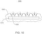
- FIG. 10 shows a cross-sectional view of a working electrode 1000 that has a plurality of sensing elements 1020 on the surface of a working electrode 1010.
- the sensing elements 1020 have an arcuate cross-sectional profile configured to promote radial diffusion of the analyte through the flux limiting membrane 1030 disposed over the sensing elements 1020 towards the working electrode 1010.
- the sensing elements have an arcuate profile.
- arcuate is meant that the cross-sectional profile of the sensing elements have an arc or rounded shape.
- the sensing elements have a shape approximating that of a half sphere, where the rounded semi-spherical portion of the sensing element is convex and extends a distance above the surface of the substrate (e.g., the surface of the working electrode).
- semi-spherical sensing elements may have a surface area that is greater that the surface area of a typical substantially flat or non-semi-spherically shaped sensing element.
- semi-spherical sensing elements may have a surface area that is 1.1 or more times greater than the surface area of a typical substantially flat (e.g., non-semi-spherically shaped) sensing element, such as 1.2 or more, including 1.3 or more, or 1.4 or more, or 1.5 or more, or 1.6 or more, or 1.7 or more, or 1.8 or more, or 1.9 or more, or 2 or more times greater than the surface area of a typical substantially flat (e.g., non-semi-spherically shaped) sensing element.
- sensing elements that have a greater surface area may facilitate an increase in the surface area of the sensing layer formulation that is able to contact the analyte as the analyte diffuses through the flux limiting membrane towards the sensing elements.
- the sensing element may also include other optional components, such as, for example, a polymer and a bi-functional, short-chain, epoxide crosslinker, such as polyethylene glycol (PEG).
- PEG polyethylene glycol
- two or more sensing elements may be provided on a sensing surface of the working electrode, where the two or more sensing elements are disposed laterally to each other.
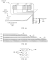
- FIG. 5C shows a schematic view of a portion of working electrode 501.
- Working electrode 501 includes a plurality of individual sensing elements 508.
- the sensing elements 508 are discontiguous, such that the sensing elements 508 are arranged into an array of individual sensing elements 508 on the working electrode 501.
- FIG. 7A shows a schematic view of a portion of an analyte sensor 700 that includes an array of sensing elements 710 deposited on a portion of a working electrode 720.
- the array of sensing elements 710 is arranged such that each row of sensing elements in the array is substantially aligned with the sensing elements in an adjacent row.
- the sensing elements 710 are arranged into an array of individual discontiguous sensing elements on the working electrode 720.
- FIG. 7B shows a schematic view of another embodiment of an analyte sensor 750.
- the portion of the analyte sensor 750 shown includes an array of sensing element 760 deposited on a portion of a working electrode 770.
- the array of sensing elements 760 is arranged such that each row of sensing elements in the array is offset from the sensing elements in an adjacent row. As shown in FIG. 7B , the sensing elements 760 are arranged into an array of individual discontiguous sensing elements on the working electrode 770. In some instances, arranging the rows of sensing elements in an offset configuration may facilitate the fabrication of an array with a greater density of sensing elements per unit area as compared to an array with rows of sensing elements substantially aligned, while still maintaining an array of individual discontiguous sensing elements.
- FIG. 8 shows an embodiment of an analyte sensor 800 that includes an array of sensing elements 810 disposed on a portion of a working electrode 820.
- the array of sensing elements 810 is arranged such that each row of sensing elements in the array is offset from the sensing elements in an adjacent row.
- the sensing elements 810 are arranged such that the edges of the sensing elements are in contact with one or more adjacent sensing elements.
- arranging the rows of sensing elements in an offset configuration with the sensing elements in contact with one or more adjacent sensing elements may facilitate the fabrication of an array with a greater density of sensing elements per unit area as compared to an array with discontiguous sensing elements.
- FIG. 9 shows a schematic of an analyte sensor 900 that includes sensing elements 910 and 930.
- Sensing elements 910 of a first layer are deposited as a first array on the surface of a working electrode 920.
- Sensing elements 930 of a second layer are deposited as a second array disposed on the sensing elements 910 of the first array.
- the sensing elements 930 of the second array are deposited such that each sensing element 930 in the second array is deposited substantially on top of an inter-feature area of the sensing elements 910 of the first array.
- the sensing elements 930 of the second array are offset from the positions of the sensing elements 910 in the first array.
- the sensing elements 930 of the second array overlap at least a portion of one or more sensing elements 910 in the underlying first array (see expanded inset in FIG. 9 ).
- the deposition of sensing elements 910 in a first array and sensing elements 930 in a second array in an offset configuration as described above may facilitate the formation of a contiguous coating of the sensing layer formulation on the surface of the working electrode 920. Additional layers of sensing elements may be deposited on the working electrode, either substantially aligned with the underlying layer or offset from the underlying layer, as desired.
- the senor is placed, transcutaneously, for example, into a subcutaneous site such that subcutaneous fluid of the site comes into contact with the sensor. In other in vivo embodiments, placement of at least a portion of the sensor may be in a blood vessel.
- the sensor operates to electrolyze an analyte of interest in the subcutaneous fluid such that a current is generated between the working electrode and the counter electrode. A value for the current associated with the working electrode is determined. If multiple working electrodes are used, current values from each of the working electrodes may be determined. A microprocessor may be used to collect these periodically determined current values or to further process these values.
- the measurement sensor is one suited for electrochemical measurement of analyte concentration, for example glucose concentration, in a bodily fluid.
- the measurement sensor includes at least a working electrode and a counter electrode. Other embodiments may further include a reference electrode.
- the working electrode may be associated with a glucose-responsive enzyme.
- a mediator may also be included.
- hydrogen peroxide which may be characterized as a mediator, is produced by a reaction of the sensor and may be used to infer the concentration of glucose.
- a mediator is added to the sensor by a manufacturer, e.g., is included with the sensor prior to use.
- a sensor may include a working electrode with a sensing surface that includes two or more sensing elements disposed laterally to each other are described in U.S. Patent Nos. 5,262,035 , 5,262,305 , 6,134,461 , 6,143,164 , 6,175,752 , 6,338,790 , 6,579,690 , 6,605,200 , 6,605,201 , 6,654,625 , 6,736,957 , 6,746,582 , 6,932,894 , 7,090,756 as well as those described in U.S. Patent Application Nos.
- embodiments disclosed herein may be incorporated into analyte monitoring systems and devices that utilize one or more rivets to attach an analytic sensor having one or more conductive traces to a sensor control unit, such as disclosed in U.S. Provisional Patent Application No. 61/498,142, filed June 17,2011 , the disclosure of which is incorporated by reference herein in its entirety.
- FIG. 11 shows an exploded perspective view of an analyte sensor test strip, the layers illustrated individually with the electrodes in a first configuration.
- test strip 1100 has a first substrate 1110, a second substrate 1120, and a spacer 1130 positioned therebetween.
- Test strip 1100 includes at least one working electrode 1140 and at least one counter electrode 1160.
- the working electrode 1140 is present on a surface of the first substrate 1110 and the counter electrode 1160 is present on a surface of the second substrate 1120 opposing the surface of the first substrate 1110 in a facing relationship with the surface of the first substrate.
- the working electrode 1140 has an array of sensing elements 1150 disposed on the sensing surface of the working electrode 1140.
- Test strip 1100 is a layered construction, in certain embodiments having a generally rectangular shape, e.g., its length is longer than its width, although other shapes are possible as well.
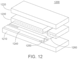
- FIG. 12 shows an exploded perspective view of an analyte sensor test strip, the layers illustrated individually with the electrodes in a second configuration. As shown in FIG.
- test strip 1200 has a first substrate 1210, a second substrate 1220, and a spacer 1230 positioned therebetween.
- Test strip 1200 includes at least one working electrode 1240 and at least one counter electrode 1260.
- the counter electrode 1260 is present on a surface of the first substrate 1210 adjacent the working electrode 1240, such that both the working electrode 1240 and the counter electrode 1260 are present on the surface of the first substrate 1210.
- the working electrode 1240 has an array of sensing elements 1250 disposed on the sensing surface of the working electrode 1240. Similar to the embodiment shown in FIG. 11 , the test strip 1200 shown in FIG.
- Analyte test strips for use with the present devices can be of any kind, size, or shape known to those skilled in the art; for example, FREESTYLE ® and FREESTYLE LITE TM test strips, as well as PRECISION TM test strips sold by ABBOTT DIABETES CARE Inc.
- the devices of the present disclosure can be configured to work with a wide variety of analyte test strips, e.g., those disclosed in U.S. Patent Application No. 11/461,725, filed August 1, 2006 ; U.S. Patent Application Publication No. 2007/0095661 ; U.S. Patent Application Publication No. 2006/0091006 ; U.S. Patent Application Publication No.
- Embodiments of the present disclosure relate to methods and devices for detecting at least one analyte, including glucose, in body fluid.
- Embodiments relate to the continuous and/or automatic in vivo monitoring of the level of one or more analytes using a continuous analyte monitoring system that includes an analyte sensor at least a portion of which is to be positioned beneath a skin surface of a user for a period of time and/or the-discrete monitoring of one or more analytes using an in vitro blood glucose (“BG") meter and an analyte test strip.
- BG in vitro blood glucose
- Embodiments include combined or combinable devices, systems and methods and/or transferring data between an in vivo continuous system and an in vivo system. In some embodiments, the systems, or at least a portion of the systems, are integrated into a single unit.
- a sensor as described herein may be an in vivo sensor or an in vitro sensor (i.e., a discrete monitoring test strip). Such a sensor can be formed on a substrate, e.g., a substantially planar substrate.
- the sensor is a wire, e.g., a working electrode wire inner portion with one or more other electrodes associated (e.g., on, including wrapped around) therewith.
- the sensor may also include at least one counter electrode (or counter/reference electrode) and/or at least one reference electrode or at least one reference/counter electrode.
- embodiments include analyte monitoring devices and systems that include an analyte sensor at least a portion of which is positionable beneath the skin surface of the user for the in vivo detection of an analyte, including glucose, lactate, and the like, in a body fluid.
- Embodiments include wholly implantable analyte sensors and analyte sensors in which only a portion of the sensor is positioned under the skin and a portion of the sensor resides above the skin, e.g., for contact to a sensor control unit (which may include a transmitter), a receiver/display unit, transceiver, processor, etc.
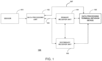
- the analyte monitoring system 100 may be a continuous monitoring system, or semi-continuous, or a discrete monitoring system.
- each component may be configured to be uniquely identified by one or more of the other components in the system so that communication conflict may be readily resolved between the various components, within the analyte monitoring system 100. For example, unique IDs, communication channels, and the like, may be used.
- the primary receiver unit 104 may include an analog interface section including an RF receiver and an antenna that is configured to communicate with the data processing unit 102 via the communication link 103, and a data processing section for processing the received data from the data processing unit 102 including data decoding, error detection and correction, data clock generation, data bit recovery, etc., or any combination thereof.
- the data processing terminal 105 may include a personal computer, a portable computer including a laptop or a handheld device (e.g., a personal digital assistant (PDA), a telephone including a cellular phone (e.g., a multimedia and Internet-enabled mobile phone including an iPhone TM , a Blackberry* or similar phone), an mp3 player (e.g., an iPOD TM , etc.), a pager, and the like), and/or a drug delivery device (e.g., an infusion device), each of which may be configured for data communication with the receiver via a wired or a wireless connection. Additionally, the data processing terminal 105 may further be connected to a data network (not shown) for storing, retrieving, updating, and/or analyzing data corresponding to the detected analyte level of the user.
- a data network not shown
- the data processing terminal 105 which may include an infusion device, e.g., an insulin pump, may be configured to receive the analyte signals from the data processing unit 102, and thus, incorporate the functions of the primary receiver unit 104 including data processing for managing the user's insulin therapy and analyte monitoring.
- FIG. 4 shows three electrodes side-by-side on the same surface of base 404, other configurations are contemplated, e.g., fewer or greater electrodes, some or all electrodes on different surfaces of the base or present on another base, some or all electrodes stacked together, electrodes of differing materials and dimensions, etc.
- Sensing elements that are in direct contact with the working electrode may contain an electron transfer agent to transfer electrons directly or indirectly between the analyte and the working electrode, and/or a catalyst to facilitate a reaction of the analyte.
- a glucose, lactate, or oxygen electrode may be formed having sensing elements which contain a catalyst, including glucose oxidase, glucose dehydrogenase, lactate oxidase, or laccase, respectively, and an electron transfer agent that facilitates the electrooxidation of the glucose, lactate, or oxygen, respectively.
- the sensing elements include one or more electron transfer agents.
- Electron transfer agents that may be employed are electroreducible and electrooxidizable ions or molecules having redox potentials that are a few hundred millivolts above or below the redox potential of the standard calomel electrode (SCE).
- the electron transfer agent may be organic, organometallic, or inorganic. Examples of organic redox species are quinones and species that in their oxidized state have quinoid structures, such as Nile blue and indophenol. Examples of organometallic redox species are metallocenes including ferrocene. Examples of inorganic redox species are hexacyanoferrate (III), ruthenium hexamine, etc. Additional examples include those described in U.S. Patent Nos. 6,736,957 , 7,501,053 and 7,754,093 , the disclosures of each of which are incorporated herein by reference in their entirety.
- Suitable copolymer substituents of poly(1-vinyl imidazole) include acrylonitrile, acrylamide, and substituted or quatemized N-vinyl imidazole, e.g., electron transfer agents with osmium complexed to a polymer or copolymer of poly(1-vinyl imidazole).
- a membrane may be formed in situ by applying an alcohol-buffer solution of a crosslinker and a modified polymer over the enzyme-containing sensing elements and allowing the solution to cure for about one to two days or other appropriate time period.
- the crosslinker-polymer solution may be applied over the sensing elements by placing a droplet or droplets of the membrane solution on the sensor, by dipping the sensor into the membrane solution, by spraying the membrane solution on the sensor, and the like.
- the thickness of the membrane is controlled by the concentration of the membrane solution, by the number of droplets of the membrane solution applied, by the number of times the sensor is dipped in the membrane solution, by the volume of membrane solution sprayed on the sensor, or by any combination of these factors.
- a membrane applied in this manner may have any combination of the following functions: (1) mass transport limitation, i.e., reduction of the flux of analyte that can reach the sensing elements, (2) biocompatibility enhancement, or (3) interferent reduction.
- the sensor control unit is typically attached to the skin of the user, for example, by adhering the sensor control unit directly to the skin of the user with an adhesive provided on at least a portion of the housing of the sensor control unit which contacts the skin or by suturing the sensor control unit to the skin through suture openings in the sensor control unit
- the senor and the electronic components within the sensor control unit are coupled via conductive contacts.
- the one or more working electrodes, counter electrode (or counter/reference electrode), optional reference electrode, and optional temperature probe are attached to individual conductive contacts.
- the conductive contacts are provided on the interior of the sensor control unit
- Other embodiments of the sensor control unit have the conductive contacts disposed on the exterior of the housing. The placement of the conductive contacts is such that they are in contact with the contact pads on the sensor when the sensor is properly positioned within the sensor control unit.
- the sensor control unit may also include digital and/or analog components utilizing semiconductor devices, including transistors.
- the sensor control unit may include other components including, for example, a bias control generator to correctly bias analog and digital semiconductor devices, an oscillator to provide a clock signal, and a digital logic and timing component to provide timing signals and logic operations for the digital components of the circuit
- the sensor circuit and the optional temperature probe circuit provide raw signals from the sensor to the measurement circuit.
- the measurement circuit converts the raw signals to a desired format, using for example, a current. to-voltage converter, cmcent-to-frequency converter, and/or a binary counter or other indicator that produces a signal proportional to the absolute value of the raw signal. This may be used, for example, to convert the raw signal to a format that can be used by digital logic circuits.
- the processing circuit may then, optionally, evaluate the data and provide commands to operate the electronics.
- Sensors may be configured to require no system calibration or no user calibration.
- a sensor may be factory calibrated and need not require further calibrating.
- calibration may be required, but may be done without user intervention, i.e., may be automatic.
- the calibration may be according to a predetermined schedule or may be dynamic, i.e., the time for which may be determined by the system on a real-time basis according to various factors, including, but not limited to, glucose concentration and/or temperature and/or rate of change of glucose, etc.
- an optional receiver may be included in the sensor control unit.
- the transmitter is a transceiver, operating as both a transmitter and a receiver.
- the receiver may be used to receive calibration data for the sensor.
- the calibration data may be used by the processing circuit to correct signals from the sensor.
- This calibration data may be transmitted by the receiver/display unit or from some other source such as a control unit ina doctor's office.
- the optional receiver may be used to receive a signal from the receiver/display units to direct the transmitter, for example, to change frequencies or frequency bands, to activate or deactivate the optional alarm system and/or to direct the transmitter to transmit at a higher rate.
- a sensor may be calibrated using only one sample of body fluid per calibration event. For example, a user need only lance a body part one time to obtain a sample for a calibration event (e.g., for a test strip), or may lance more than one time within a short period of time if an insufficient volume of sample is firstly obtained.
- Embodiments include obtaining and using multiple samples of body fluid for a given calibration event, where glucose values of each sample are substantially similar. Data obtained from a given calibration event may be used independently to calibrate or combined with data obtained from previous calibration events, e.g., averaged including weighted averaged, etc., to calibrate. In certain embodiments, a system need only be calibrated once by a user, where recalibration of the system is not required.
- calibration data may also be used to obtain calibration data.
- This type of calibration data may supplant or supplement factory-determined calibration values.
- calibration data may be required at periodic intervals, for example, every eight hours, once a day, or once a week, to confirm that accurate analyte levels are being reported. Calibration may also be required each time a new sensor is implanted or if the sensor exceeds a threshold minimum or maximum value or if the rate of change in the sensor signal exceeds a threshold value. In some cases, it may be necessary to wait a period of time after the implantation of the sensor before calibrating to allow the sensor to achieve equilibrium. In some embodiments, the sensor is calibrated only after it has been inserted. In other embodiments, no calibration of the sensor is needed.
- the analyte monitoring device includes a sensor control unit and a sensor.
- the processing circuit of the sensor control unit is able to determine a level of the analyte and activate an alarm system if the analyte level exceeds a threshold value.
- the sensor control unit in these embodiments, has an alarm system and may also include a display, such as an LCD or LED display.
- a threshold value is exceeded if the datapoint has a value that is beyond the threshold value in a direction indicating a particular condition. For example, a datapoint which correlates to a glucose level of 200 mg/dL exceeds a threshold value for hyperglycemia of 180 mg/dL, because the datapoint indicates that the user has entered a hyperglycemic state. As another example, a datapoint which correlates to a glucose level of 65 mg/dL exceeds a threshold value for hypoglycemia of 70 mg/dL because the datapoint indicates that the user is hypoglycemic as defined by the threshold value. However, a datapoint which correlates to a glucose level of 75 mg/dL would not exceed the same threshold value of 70 mg/dL for hypoglycemia because the datapoint does not indicate that particular condition as defined by the chosen threshold value.
- An alarm may also be activated if the sensor readings indicate a value that is outside of (e.g., above or below) a measurement range of the sensor.
- the physiologically relevant measurement range is typically 30-400 mgldL, including 40-300 mg/dL and 50-250 mg/dL, of glucose in the interstitial fluid.
- the alarm system may also, or alternatively, be activated when the rate of change or acceleration of the rate of change in analyte level increase or decrease reaches or exceeds a threshold rate or acceleration.
- a threshold rate or acceleration For example, in the case of a subcutaneous glucose monitor, the alarm system may be activated if the rate of change in glucose concentration exceeds a threshold value which may indicate that a hyperglycemic or hypoglycemic condition is likely to occur.
- the alarm system is activated if the acceleration of die rate of change in glucose concentration exceeds a threshold value which may indicate that a hyperglycemic or hypoglycemic condition is likely to occur.
- a system may also include system alarms that notify a user of system information such as battery condition, calibration, sensor dislodgment, sensor malfunction, etc.
- Alarms may be, for example, auditory and/or visual.
- Other sensory-stimulating alarm systems may be used including alarm systems which heat, cool, vibrate, or produce a mild electrical shock when activated.
- the subject invention also includes sensors used in sensor-based drug delivery systems.
- the system may provide a drug to counteract the high or low level of the analyte in response to the signals from one or more sensors. Alternatively, the system may monitor the drug concentration to ensure that the drug remains within a desired therapeutic range.
- the drug delivery system may include one or more (e.g., two or more) sensors, a processing unit such as a transmitter, a receiver/display unit, and a drug administration system. In some cases, some or all components may be integrated in a single unit.
- a sensor-based drug delivery system may use data from the one or more sensors to provide necessary input for a control algorithm/mechanism to adjust the administration of drugs, e.g., automatically or semi-automatically.
- a glucose sensor may be used to control and adjust the administration of insulin from an external or implanted insulin pump.
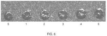
- FIG. 6 shows a photograph of a working electrode coated with six sensing elements (labeled I to 6) with a radius of approximately 150 ⁇ m each at a distance of approximately 150 ⁇ m from each other.
- the resulting sensors have a coefficient of variation in sensitivity of 5% or less.
- the diameters of each sensing element in FIG. 6 are shown in Table 1 below.
Landscapes
- Health & Medical Sciences (AREA)
- Life Sciences & Earth Sciences (AREA)
- Chemical & Material Sciences (AREA)
- Physics & Mathematics (AREA)
- Engineering & Computer Science (AREA)
- Organic Chemistry (AREA)
- Molecular Biology (AREA)
- General Health & Medical Sciences (AREA)
- Biophysics (AREA)
- Proteomics, Peptides & Aminoacids (AREA)
- Zoology (AREA)
- Wood Science & Technology (AREA)
- Pathology (AREA)
- Surgery (AREA)
- Veterinary Medicine (AREA)
- Public Health (AREA)
- Animal Behavior & Ethology (AREA)
- Medical Informatics (AREA)
- Heart & Thoracic Surgery (AREA)
- Biomedical Technology (AREA)
- Optics & Photonics (AREA)
- Bioinformatics & Cheminformatics (AREA)
- Genetics & Genomics (AREA)
- Emergency Medicine (AREA)
- Analytical Chemistry (AREA)
- General Engineering & Computer Science (AREA)
- Microbiology (AREA)
- Biochemistry (AREA)
- Biotechnology (AREA)
- Immunology (AREA)
- General Chemical & Material Sciences (AREA)
- Chemical Kinetics & Catalysis (AREA)
- Measurement Of The Respiration, Hearing Ability, Form, And Blood Characteristics Of Living Organisms (AREA)
- Apparatus Associated With Microorganisms And Enzymes (AREA)
Applications Claiming Priority (4)
| Application Number | Priority Date | Filing Date | Title |
|---|---|---|---|
| US42137110P | 2010-12-09 | 2010-12-09 | |
| EP21179281.7A EP3954781B1 (de) | 2010-12-09 | 2011-12-08 | Analytsensoren mit einer sensoroberfläche mit kleinen erfassungspunkten |
| EP11846841.2A EP2649191B1 (de) | 2010-12-09 | 2011-12-08 | Analytsensoren mit einer sensoroberfläche mit kleinen erfassungspunkten |
| PCT/US2011/064000 WO2012078908A1 (en) | 2010-12-09 | 2011-12-08 | Analyte sensors with a sensing surface having small sensing spots |
Related Parent Applications (2)
| Application Number | Title | Priority Date | Filing Date |
|---|---|---|---|
| EP21179281.7A Division EP3954781B1 (de) | 2010-12-09 | 2011-12-08 | Analytsensoren mit einer sensoroberfläche mit kleinen erfassungspunkten |
| EP11846841.2A Division EP2649191B1 (de) | 2010-12-09 | 2011-12-08 | Analytsensoren mit einer sensoroberfläche mit kleinen erfassungspunkten |
Publications (2)
| Publication Number | Publication Date |
|---|---|
| EP4397242A2 true EP4397242A2 (de) | 2024-07-10 |
| EP4397242A3 EP4397242A3 (de) | 2024-08-28 |
Family
ID=46200043
Family Applications (3)
| Application Number | Title | Priority Date | Filing Date |
|---|---|---|---|
| EP11846841.2A Active EP2649191B1 (de) | 2010-12-09 | 2011-12-08 | Analytsensoren mit einer sensoroberfläche mit kleinen erfassungspunkten |
| EP21179281.7A Active EP3954781B1 (de) | 2010-12-09 | 2011-12-08 | Analytsensoren mit einer sensoroberfläche mit kleinen erfassungspunkten |
| EP24158401.0A Pending EP4397242A3 (de) | 2010-12-09 | 2011-12-08 | Analytsensoren mit einer sensoroberfläche mit kleinen erfassungspunkten |
Family Applications Before (2)
| Application Number | Title | Priority Date | Filing Date |
|---|---|---|---|
| EP11846841.2A Active EP2649191B1 (de) | 2010-12-09 | 2011-12-08 | Analytsensoren mit einer sensoroberfläche mit kleinen erfassungspunkten |
| EP21179281.7A Active EP3954781B1 (de) | 2010-12-09 | 2011-12-08 | Analytsensoren mit einer sensoroberfläche mit kleinen erfassungspunkten |
Country Status (8)
| Country | Link |
|---|---|
| US (5) | US10327677B2 (de) |
| EP (3) | EP2649191B1 (de) |
| CN (2) | CN107961016B (de) |
| AU (1) | AU2011338255B2 (de) |
| CA (1) | CA2814205C (de) |
| ES (1) | ES2980736T3 (de) |
| FI (1) | FI3954781T3 (de) |
| WO (1) | WO2012078908A1 (de) |
Families Citing this family (58)
| Publication number | Priority date | Publication date | Assignee | Title |
|---|---|---|---|---|
| EP2649191B1 (de) | 2010-12-09 | 2021-06-16 | Abbott Diabetes Care, Inc. | Analytsensoren mit einer sensoroberfläche mit kleinen erfassungspunkten |
| EP4122384A1 (de) | 2011-06-16 | 2023-01-25 | Abbott Diabetes Care, Inc. | Analytüberwachungsvorrichtungen, -verfahren und -systeme mit temperaturkompensation |
| WO2014045584A1 (ja) * | 2012-09-19 | 2014-03-27 | パナソニックヘルスケア株式会社 | バイオセンサ及びバイオセンサの製造方法 |
| US9743871B2 (en) * | 2012-09-24 | 2017-08-29 | Dexcom, Inc. | Multiple electrode system for a continuous analyte sensor, and related methods |
| US10898116B2 (en) | 2013-03-15 | 2021-01-26 | Cambridge Medical Technologies LLC | Methods of manufacture to optimize performance of transdermal sampling and analysis device |
| JP6450757B2 (ja) * | 2013-07-24 | 2019-01-09 | カリフォルニア インスティチュート オブ テクノロジー | 埋め込み型完全集積化電気化学センサの設計及び作製 |
| US10360368B2 (en) | 2013-12-27 | 2019-07-23 | Abbott Diabetes Care Inc. | Application interface and display control in an analyte monitoring environment |
| EP3087771B1 (de) | 2013-12-27 | 2020-06-17 | Abbott Diabetes Care, Inc. | Systeme, vorrichtungen und verfahren zur authentifizierung in einer analytüberwachungsumgebung |
| WO2016205378A1 (en) | 2015-06-15 | 2016-12-22 | Abbott Diabetes Care Inc. | Stabilized lactate responsive enzymes, electrodes and sensors, and methods for making and using the same |
| US10888272B2 (en) | 2015-07-10 | 2021-01-12 | Abbott Diabetes Care Inc. | Systems, devices, and methods for meal information collection, meal assessment, and analyte data correlation |
| US10386365B2 (en) | 2015-12-07 | 2019-08-20 | Nanohmics, Inc. | Methods for detecting and quantifying analytes using ionic species diffusion |
| US11988662B2 (en) | 2015-12-07 | 2024-05-21 | Nanohmics, Inc. | Methods for detecting and quantifying gas species analytes using differential gas species diffusion |
| US10386351B2 (en) | 2015-12-07 | 2019-08-20 | Nanohmics, Inc. | Methods for detecting and quantifying analytes using gas species diffusion |
| US9939371B2 (en) * | 2016-02-01 | 2018-04-10 | Empire Technology Development Llc | Systems and methods for multi-component detection |
| ES2974312T3 (es) | 2016-03-04 | 2024-06-26 | Abbott Diabetes Care Inc | Enzimas sensibles dependientes de NAD(P), electrodos y sensores y procedimientos para la fabricación y utilización de los mismos |
| WO2019006413A1 (en) | 2017-06-30 | 2019-01-03 | Abbott Diabetes Care | METHOD AND APPARATUS FOR ANALYTE DETECTION USING ELECTROCHEMICAL BIOSENSOR |
| EP4218568A1 (de) | 2017-08-18 | 2023-08-02 | Abbott Diabetes Care Inc. | Analytüberwachungssystem, das eine gemessene elektrische eigenschaft des in-vivo-analytsensors des systems als individualisierte kalibrierungsinformation speichert |
| ES3023573T3 (en) * | 2017-09-18 | 2025-06-02 | Hoffmann La Roche | Electrochemical sensor for detecting at least one analyte |
| WO2019089476A1 (en) | 2017-10-30 | 2019-05-09 | Abbott Diabetes Care Inc. | Transcutaneous sensor with dual electrodes and methods of detecting and compensating for withdrawal of a transcutaneous sensor from a patient |
| CN111818849A (zh) | 2018-02-05 | 2020-10-23 | 雅培糖尿病护理股份有限公司 | 与分析物传感器相关联的注释和事件日志信息 |
| US20210236028A1 (en) | 2018-05-17 | 2021-08-05 | Abbott Diabetes Care Inc. | Analyte sensor antimicrobial configurations and adhesives |
| CA3108070A1 (en) | 2018-08-23 | 2020-02-27 | Abbott Diabetes Care Inc. | Sensors and methods for measuring ph |
| US11744492B2 (en) * | 2018-08-29 | 2023-09-05 | Medtronic, Inc. | Electrochemical sensor including multiple work electrodes and common reference electrode |
| US10852268B2 (en) * | 2018-08-29 | 2020-12-01 | Medtronic, Inc. | Electrochemical sensor including multiple work electrodes and common reference electrode |
| CN109470604B (zh) * | 2018-11-02 | 2021-03-05 | 吉林大学 | 一种具有仿生表面结构的液滴分布检测传感器及检测方法 |
| CN109737861A (zh) * | 2018-11-22 | 2019-05-10 | 厦门大学 | 一种可调型蛋白质基柔性应变传感器及其制备方法、应用 |
| EP4552566A1 (de) * | 2019-01-28 | 2025-05-14 | Abbott Diabetes Care, Inc. | Analytsensoren und messverfahren zum nachweis von kreatinin |
| EP4663121A1 (de) | 2019-01-28 | 2025-12-17 | Abbott Diabetes Care Inc. | Analytsensoren mit mehreren enzymen |
| DK3917396T3 (da) | 2019-01-28 | 2024-12-02 | Abbott Diabetes Care Inc | Analytsensorer, der er forsynet med dualdetektering af glukose og ketoner |
| EP4552565A1 (de) | 2019-01-28 | 2025-05-14 | Abbott Diabetes Care, Inc. | Analytsensoren und messverfahren für den doppelnachweis von glucose und ethanol |
| US11633129B2 (en) | 2019-04-05 | 2023-04-25 | Cambridge Medical Technologies LLC | Non-invasive transdermal sampling and analysis device incorporating redox cofactors |
| TWI695174B (zh) * | 2019-04-25 | 2020-06-01 | 國立交通大學 | 微型化感測探針及其製造方法 |
| CN113853160B (zh) * | 2019-06-26 | 2024-07-09 | 聚合物技术系统公司 | 用于降低电化学生物传感器中氧张力的系统和方法 |
| TWI723731B (zh) * | 2019-08-02 | 2021-04-01 | 華廣生技股份有限公司 | 生物感測器之植入裝置及其植入方法 |
| CN112294320B (zh) * | 2019-08-02 | 2024-06-11 | 华广生技股份有限公司 | 植入式微型生物传感器 |
| US11375931B2 (en) | 2019-08-08 | 2022-07-05 | Cambridge Medical Technologies LLC | Non-invasive transdermal sampling and analysis device incorporating an electrochemical bioassay |
| US20220218240A1 (en) * | 2019-08-19 | 2022-07-14 | Medtrum Technologies Inc. | Sensing device |
| US11776684B2 (en) | 2019-09-26 | 2023-10-03 | Pacesetter, Inc | Method and device for managing energy usage by a medical device |
| IL273038B (en) | 2020-03-03 | 2022-02-01 | Ben Zion Karmon | bone graft |
| US20210386339A1 (en) | 2020-06-16 | 2021-12-16 | Abbott Diabetes Care Inc. | Analyte sensors featuring working electrode asperity planing for decreasing interferent signal |
| CA3181614A1 (en) | 2020-06-16 | 2021-12-23 | Abbott Diabetes Care Inc. | Analyte sensors featuring a reduced-area working electrode for decreasing interferent signal |
| EP4176447A1 (de) | 2020-07-01 | 2023-05-10 | Abbott Diabetes Care Inc. | Systeme, vorrichtungen und verfahren zur sammlung von mahlzeitinformationen, mahlzeitbeurteilung und korrelation von analytdaten |
| CN115867196A (zh) | 2020-07-08 | 2023-03-28 | 雅培糖尿病护理公司 | 以针对减小干扰信号的增强为特征的分析物传感器 |
| USD957438S1 (en) | 2020-07-29 | 2022-07-12 | Abbott Diabetes Care Inc. | Display screen or portion thereof with graphical user interface |
| EP4000517B1 (de) | 2020-11-23 | 2026-04-15 | Roche Diabetes Care GmbH | Verfahren zur herstellung einer arbeitselektrode eines analytsensors |
| JP2024500980A (ja) * | 2020-12-23 | 2024-01-10 | アボット ダイアベティス ケア インコーポレイテッド | 干渉物質信号が低減された検体センサ及び方法 |
| AU2022212954B2 (en) | 2021-01-26 | 2025-04-24 | Abbott Diabetes Care Inc. | Systems, devices, and methods related to ketone sensors |
| EP4448783A1 (de) | 2021-12-13 | 2024-10-23 | Heraeus Medical GmbH | Tests und verfahren zum nachweis bakterieller infektionen |
| US20230338945A1 (en) * | 2022-04-21 | 2023-10-26 | Arkray, Inc. | Biosensor and method of manufacturing biosensor |
| US12590920B2 (en) * | 2022-04-21 | 2026-03-31 | Arkray, Inc. | Biosensor |
| WO2024021843A1 (zh) * | 2022-07-24 | 2024-02-01 | 深圳硅基传感科技有限公司 | 对乳酸进行监测的传感器及其制备方法 |
| EP4357778A1 (de) | 2022-10-20 | 2024-04-24 | Heraeus Medical GmbH | Behandlung von mikrobiellen infektionen mit diagnose durch biomarker d-lactat |
| CN120584190A (zh) | 2023-01-25 | 2025-09-02 | 雅培糖尿病护理公司 | 用于分析物传感器的温度不敏感膜 |
| EP4727449A1 (de) | 2023-06-16 | 2026-04-22 | Abbott Diabetes Care Inc. | Analytüberwachungsvorrichtungen mit dehnungsmesser |
| US20250064355A1 (en) | 2023-08-25 | 2025-02-27 | Abbott Diabetes Care Inc. | Analyte monitoring systems and methods for monitoring multiple analytes |
| US20250127428A1 (en) * | 2023-10-19 | 2025-04-24 | Arkray, Inc. | Biosensor |
| WO2025217600A1 (en) | 2024-04-12 | 2025-10-16 | Advanced Neuromodulation Systems, Inc. | Methods and systems for managing outcomes for weight-loss glp-1 receptor agonist therapies using biochemical data-trained models and/or other patient centric analysis |
| US20260007334A1 (en) * | 2024-07-03 | 2026-01-08 | Laxmi Therapeutic Devices, Inc. | Small-scale analyte sensors |
Citations (33)
| Publication number | Priority date | Publication date | Assignee | Title |
|---|---|---|---|---|
| US2135710A (en) | 1937-07-29 | 1938-11-08 | Bernhard C Grunig | Coin chute |
| US5262305A (en) | 1991-03-04 | 1993-11-16 | E. Heller & Company | Interferant eliminating biosensors |
| US5262035A (en) | 1989-08-02 | 1993-11-16 | E. Heller And Company | Enzyme electrodes |
| US5264104A (en) | 1989-08-02 | 1993-11-23 | Gregg Brian A | Enzyme electrodes |
| US5320715A (en) | 1994-01-14 | 1994-06-14 | Lloyd Berg | Separation of 1-pentanol from cyclopentanol by extractive distillation |
| US5593852A (en) | 1993-12-02 | 1997-01-14 | Heller; Adam | Subcutaneous glucose electrode |
| US6071391A (en) | 1997-09-12 | 2000-06-06 | Nok Corporation | Enzyme electrode structure |
| US6134461A (en) | 1998-03-04 | 2000-10-17 | E. Heller & Company | Electrochemical analyte |
| US6143164A (en) | 1997-02-06 | 2000-11-07 | E. Heller & Company | Small volume in vitro analyte sensor |
| US6175752B1 (en) | 1998-04-30 | 2001-01-16 | Therasense, Inc. | Analyte monitoring device and methods of use |
| US6338790B1 (en) | 1998-10-08 | 2002-01-15 | Therasense, Inc. | Small volume in vitro analyte sensor with diffusible or non-leachable redox mediator |
| US6579690B1 (en) | 1997-12-05 | 2003-06-17 | Therasense, Inc. | Blood analyte monitoring through subcutaneous measurement |
| US6605200B1 (en) | 1999-11-15 | 2003-08-12 | Therasense, Inc. | Polymeric transition metal complexes and uses thereof |
| US6616819B1 (en) | 1999-11-04 | 2003-09-09 | Therasense, Inc. | Small volume in vitro analyte sensor and methods |
| US6650471B2 (en) | 2001-09-17 | 2003-11-18 | Dai Nippon Printing Co., Ltd. | Resin composition for production of optical element, the optical element, and projection screen |
| US6654625B1 (en) | 1999-06-18 | 2003-11-25 | Therasense, Inc. | Mass transport limited in vivo analyte sensor |
| US6736957B1 (en) | 1997-10-16 | 2004-05-18 | Abbott Laboratories | Biosensor electrode mediators for regeneration of cofactors and process for using |
| US6746582B2 (en) | 2000-05-12 | 2004-06-08 | Therasense, Inc. | Electrodes with multilayer membranes and methods of making the electrodes |
| US6932894B2 (en) | 2001-05-15 | 2005-08-23 | Therasense, Inc. | Biosensor membranes composed of polymers containing heterocyclic nitrogens |
| US20060025661A1 (en) | 2004-08-02 | 2006-02-02 | Sweeney Robert J | Device for monitoring fluid status |
| US20060091006A1 (en) | 1999-11-04 | 2006-05-04 | Yi Wang | Analyte sensor with insertion monitor, and methods |
| US20070068807A1 (en) | 2005-09-27 | 2007-03-29 | Abbott Diabetes Care, Inc. | In vitro analyte sensor and methods of use |
| US20070095661A1 (en) | 2005-10-31 | 2007-05-03 | Yi Wang | Method of making, and, analyte sensor |
| US20070108048A1 (en) | 2005-11-17 | 2007-05-17 | Abbott Diabetes Care, Inc. | Sensors |
| US20070199818A1 (en) | 2006-02-28 | 2007-08-30 | Adrian Petyt | Biosensors and Methods of Making |
| US20080066305A1 (en) | 2006-08-01 | 2008-03-20 | Abbott Diabetes Care Inc. | Analyte sensors and methods |
| US20080102441A1 (en) | 2006-10-31 | 2008-05-01 | Ting Chen | Analyte Sensors and Methods |
| US20080148873A1 (en) | 2006-12-22 | 2008-06-26 | Yi Wang | Analyte Sensors and Methods of Use |
| US20080267823A1 (en) | 2007-04-27 | 2008-10-30 | Abbott Diabetes Care, Inc. | Identification Of A Strip Type By The Meter Using Conductive Patterns On The Strip |
| US7501053B2 (en) | 2002-10-23 | 2009-03-10 | Abbott Laboratories | Biosensor having improved hematocrit and oxygen biases |
| US20090095625A1 (en) | 2007-10-12 | 2009-04-16 | Forrow Nigel J | Mediator-Stabilized Reagent Compositions for Use in Biosensor Electrodes |
| US7811231B2 (en) | 2002-12-31 | 2010-10-12 | Abbott Diabetes Care Inc. | Continuous glucose monitoring system and methods of use |
| US10237408B1 (en) | 2018-02-15 | 2019-03-19 | Noble Systems Corporation | Establishing a target handle time for a communication in a contact center using analytics |
Family Cites Families (38)
| Publication number | Priority date | Publication date | Assignee | Title |
|---|---|---|---|---|
| US5320725A (en) | 1989-08-02 | 1994-06-14 | E. Heller & Company | Electrode and method for the detection of hydrogen peroxide |
| US6139718A (en) * | 1997-03-25 | 2000-10-31 | Cygnus, Inc. | Electrode with improved signal to noise ratio |
| US6764581B1 (en) * | 1997-09-05 | 2004-07-20 | Abbott Laboratories | Electrode with thin working layer |
| US8346337B2 (en) * | 1998-04-30 | 2013-01-01 | Abbott Diabetes Care Inc. | Analyte monitoring device and methods of use |
| CA2333875C (en) * | 1998-06-01 | 2005-10-11 | Roche Diagnostics Corporation | Redox reversible bipyridyl osmium complex conjugates |
| US6591125B1 (en) | 2000-06-27 | 2003-07-08 | Therasense, Inc. | Small volume in vitro analyte sensor with diffusible or non-leachable redox mediator |
| US7955559B2 (en) * | 2005-11-15 | 2011-06-07 | Nanomix, Inc. | Nanoelectronic electrochemical test device |
| US7452452B2 (en) * | 2002-04-29 | 2008-11-18 | The Trustees Of Boston College | Carbon nanotube nanoelectrode arrays |
| WO2004001404A1 (en) * | 2002-06-19 | 2003-12-31 | Becton, Dickinson And Company | Microfabricated sensor arrays |
| US20050272989A1 (en) * | 2004-06-04 | 2005-12-08 | Medtronic Minimed, Inc. | Analyte sensors and methods for making and using them |
| US7134999B2 (en) * | 2003-04-04 | 2006-11-14 | Dexcom, Inc. | Optimized sensor geometry for an implantable glucose sensor |
| WO2005010518A1 (en) * | 2003-07-23 | 2005-02-03 | Dexcom, Inc. | Rolled electrode array and its method for manufacture |
| US7920906B2 (en) * | 2005-03-10 | 2011-04-05 | Dexcom, Inc. | System and methods for processing analyte sensor data for sensor calibration |
| DE602004028649D1 (de) * | 2003-11-13 | 2010-09-23 | Medtronic Minimed Inc | Langzeit-analytensensor-anordnung |
| US8414489B2 (en) * | 2003-11-13 | 2013-04-09 | Medtronic Minimed, Inc. | Fabrication of multi-sensor arrays |
| US8989833B2 (en) * | 2004-07-13 | 2015-03-24 | Dexcom, Inc. | Transcutaneous analyte sensor |
| US8333874B2 (en) * | 2005-12-09 | 2012-12-18 | Flexible Medical Systems, Llc | Flexible apparatus and method for monitoring and delivery |
| CN101454667B (zh) * | 2005-12-27 | 2013-04-24 | 拜尔保健有限公司 | 使用带有至少一个孔的基板的电化学传感器系统及其制造方法 |
| WO2007120552A2 (en) * | 2006-04-11 | 2007-10-25 | Bayer Healthcare Llc | Monitoring the laydown of a reagent like potassium ferricyanide using xrf spectrometry |
| EP2091430A4 (de) | 2006-11-30 | 2010-01-06 | Abbott Diabetes Care Inc | Mit einem lyotropen flüssigkristall beschichtete analytüberwachungsvorrichtung und verfahren zu ihrer verwendung |
| WO2008078319A1 (en) * | 2006-12-22 | 2008-07-03 | Medingo Ltd. | Fluid delivery with in vivo electrochemical analyte sensing |
| US8808515B2 (en) | 2007-01-31 | 2014-08-19 | Abbott Diabetes Care Inc. | Heterocyclic nitrogen containing polymers coated analyte monitoring device and methods of use |
| US8260558B2 (en) * | 2007-05-14 | 2012-09-04 | Abbott Diabetes Care Inc. | Method and apparatus for providing data processing and control in a medical communication system |
| WO2009097357A1 (en) * | 2008-01-29 | 2009-08-06 | Medtronic Minimed, Inc. | Analyte sensors having nanostructured electrodes and methods for making and using them |
| US8262874B2 (en) | 2008-04-14 | 2012-09-11 | Abbott Diabetes Care Inc. | Biosensor coating composition and methods thereof |
| US8620398B2 (en) * | 2008-06-02 | 2013-12-31 | Abbott Diabetes Care Inc. | Reference electrodes having an extended lifetime for use in long term amperometric sensors |
| US8280474B2 (en) * | 2008-06-02 | 2012-10-02 | Abbott Diabetes Care Inc. | Reference electrodes having an extended lifetime for use in long term amperometric sensors |
| EP2163190A1 (de) * | 2008-09-11 | 2010-03-17 | Roche Diagnostics GmbH | Elektrodensystem für Messung einer Analytkonzentration in-vivo |
| EP2355705A4 (de) * | 2008-11-11 | 2013-12-25 | Isense Corp | Implantierbarer langzeit-biosensor |
| US20100213057A1 (en) | 2009-02-26 | 2010-08-26 | Benjamin Feldman | Self-Powered Analyte Sensor |
| EP2266458A1 (de) * | 2009-06-23 | 2010-12-29 | Roche Diagnostics GmbH | Sensor für in-vivo Messungen |
| US8354013B2 (en) | 2009-11-24 | 2013-01-15 | Abbott Diabetes Care Inc. | Analyte sensors comprising high-boiling point solvents |
| US9042954B2 (en) | 2009-11-24 | 2015-05-26 | Abbott Diabetes Care Inc. | Analyte sensors comprising hydrogel membranes |
| US20110124993A1 (en) | 2009-11-24 | 2011-05-26 | Abbott Diabetes Care Inc. | Analyte Sensors Comprising Self-Polymerizing Hydrogels |
| US9084570B2 (en) * | 2010-10-08 | 2015-07-21 | Roche Diagnostics Operations, Inc. | Electrochemical sensor having symmetrically distributed analyte sensitive areas |
| US20120088997A1 (en) * | 2010-10-12 | 2012-04-12 | Anthony Guiseppi-Elie | Implantable biochip for managing trauma--induced hemorrhage |
| EP2649191B1 (de) | 2010-12-09 | 2021-06-16 | Abbott Diabetes Care, Inc. | Analytsensoren mit einer sensoroberfläche mit kleinen erfassungspunkten |
| CA3105324A1 (en) | 2011-06-17 | 2012-12-20 | Abbott Diabetes Care Inc. | Connectors for making connections between analyte sensors and other devices |
-
2011
- 2011-12-08 EP EP11846841.2A patent/EP2649191B1/de active Active
- 2011-12-08 FI FIEP21179281.7T patent/FI3954781T3/fi active
- 2011-12-08 EP EP21179281.7A patent/EP3954781B1/de active Active
- 2011-12-08 CN CN201711370655.8A patent/CN107961016B/zh active Active
- 2011-12-08 CA CA2814205A patent/CA2814205C/en active Active
- 2011-12-08 US US13/315,034 patent/US10327677B2/en active Active
- 2011-12-08 CN CN2011800533104A patent/CN103261433A/zh active Pending
- 2011-12-08 ES ES21179281T patent/ES2980736T3/es active Active
- 2011-12-08 AU AU2011338255A patent/AU2011338255B2/en active Active
- 2011-12-08 EP EP24158401.0A patent/EP4397242A3/de active Pending
- 2011-12-08 WO PCT/US2011/064000 patent/WO2012078908A1/en not_active Ceased
-
2019
- 2019-03-20 US US16/358,918 patent/US11457840B2/en active Active
-
2021
- 2021-04-14 US US17/230,149 patent/US12042275B2/en active Active
-
2022
- 2022-08-26 US US17/822,505 patent/US12029554B2/en active Active
-
2024
- 2024-06-03 US US18/732,292 patent/US20240407675A1/en active Pending
Patent Citations (37)
| Publication number | Priority date | Publication date | Assignee | Title |
|---|---|---|---|---|
| US2135710A (en) | 1937-07-29 | 1938-11-08 | Bernhard C Grunig | Coin chute |
| US5262035A (en) | 1989-08-02 | 1993-11-16 | E. Heller And Company | Enzyme electrodes |
| US5264104A (en) | 1989-08-02 | 1993-11-23 | Gregg Brian A | Enzyme electrodes |
| US5262305A (en) | 1991-03-04 | 1993-11-16 | E. Heller & Company | Interferant eliminating biosensors |
| US5593852A (en) | 1993-12-02 | 1997-01-14 | Heller; Adam | Subcutaneous glucose electrode |
| US5320715A (en) | 1994-01-14 | 1994-06-14 | Lloyd Berg | Separation of 1-pentanol from cyclopentanol by extractive distillation |
| US6143164A (en) | 1997-02-06 | 2000-11-07 | E. Heller & Company | Small volume in vitro analyte sensor |
| US6071391A (en) | 1997-09-12 | 2000-06-06 | Nok Corporation | Enzyme electrode structure |
| US6893545B2 (en) | 1997-09-12 | 2005-05-17 | Therasense, Inc. | Biosensor |
| US6736957B1 (en) | 1997-10-16 | 2004-05-18 | Abbott Laboratories | Biosensor electrode mediators for regeneration of cofactors and process for using |
| US6579690B1 (en) | 1997-12-05 | 2003-06-17 | Therasense, Inc. | Blood analyte monitoring through subcutaneous measurement |
| US6134461A (en) | 1998-03-04 | 2000-10-17 | E. Heller & Company | Electrochemical analyte |
| US6175752B1 (en) | 1998-04-30 | 2001-01-16 | Therasense, Inc. | Analyte monitoring device and methods of use |
| US6338790B1 (en) | 1998-10-08 | 2002-01-15 | Therasense, Inc. | Small volume in vitro analyte sensor with diffusible or non-leachable redox mediator |
| US6592745B1 (en) | 1998-10-08 | 2003-07-15 | Therasense, Inc. | Method of using a small volume in vitro analyte sensor with diffusible or non-leachable redox mediator |
| US6654625B1 (en) | 1999-06-18 | 2003-11-25 | Therasense, Inc. | Mass transport limited in vivo analyte sensor |
| US6616819B1 (en) | 1999-11-04 | 2003-09-09 | Therasense, Inc. | Small volume in vitro analyte sensor and methods |
| US20060091006A1 (en) | 1999-11-04 | 2006-05-04 | Yi Wang | Analyte sensor with insertion monitor, and methods |
| US7090756B2 (en) | 1999-11-15 | 2006-08-15 | Therasense Inc. | Transition metal complexes with bidentate ligand having an imidazole ring |
| US6605200B1 (en) | 1999-11-15 | 2003-08-12 | Therasense, Inc. | Polymeric transition metal complexes and uses thereof |
| US6746582B2 (en) | 2000-05-12 | 2004-06-08 | Therasense, Inc. | Electrodes with multilayer membranes and methods of making the electrodes |
| US6932894B2 (en) | 2001-05-15 | 2005-08-23 | Therasense, Inc. | Biosensor membranes composed of polymers containing heterocyclic nitrogens |
| US6650471B2 (en) | 2001-09-17 | 2003-11-18 | Dai Nippon Printing Co., Ltd. | Resin composition for production of optical element, the optical element, and projection screen |
| US7501053B2 (en) | 2002-10-23 | 2009-03-10 | Abbott Laboratories | Biosensor having improved hematocrit and oxygen biases |
| US7754093B2 (en) | 2002-10-23 | 2010-07-13 | Abbott Diabetes Care Inc. | Biosensor having improved hematocrit and oxygen biases |
| US7811231B2 (en) | 2002-12-31 | 2010-10-12 | Abbott Diabetes Care Inc. | Continuous glucose monitoring system and methods of use |
| US20060025661A1 (en) | 2004-08-02 | 2006-02-02 | Sweeney Robert J | Device for monitoring fluid status |
| US20070068807A1 (en) | 2005-09-27 | 2007-03-29 | Abbott Diabetes Care, Inc. | In vitro analyte sensor and methods of use |
| US20070095661A1 (en) | 2005-10-31 | 2007-05-03 | Yi Wang | Method of making, and, analyte sensor |
| US20070108048A1 (en) | 2005-11-17 | 2007-05-17 | Abbott Diabetes Care, Inc. | Sensors |
| US20070199818A1 (en) | 2006-02-28 | 2007-08-30 | Adrian Petyt | Biosensors and Methods of Making |
| US20080066305A1 (en) | 2006-08-01 | 2008-03-20 | Abbott Diabetes Care Inc. | Analyte sensors and methods |
| US20080102441A1 (en) | 2006-10-31 | 2008-05-01 | Ting Chen | Analyte Sensors and Methods |
| US20080148873A1 (en) | 2006-12-22 | 2008-06-26 | Yi Wang | Analyte Sensors and Methods of Use |
| US20080267823A1 (en) | 2007-04-27 | 2008-10-30 | Abbott Diabetes Care, Inc. | Identification Of A Strip Type By The Meter Using Conductive Patterns On The Strip |
| US20090095625A1 (en) | 2007-10-12 | 2009-04-16 | Forrow Nigel J | Mediator-Stabilized Reagent Compositions for Use in Biosensor Electrodes |
| US10237408B1 (en) | 2018-02-15 | 2019-03-19 | Noble Systems Corporation | Establishing a target handle time for a communication in a contact center using analytics |
Also Published As
| Publication number | Publication date |
|---|---|
| US20230165489A1 (en) | 2023-06-01 |
| FI3954781T3 (fi) | 2024-10-08 |
| CN103261433A (zh) | 2013-08-21 |
| CN107961016B (zh) | 2021-06-15 |
| US12029554B2 (en) | 2024-07-09 |
| US10327677B2 (en) | 2019-06-25 |
| US20210251530A1 (en) | 2021-08-19 |
| CA2814205C (en) | 2025-05-06 |
| US20120150005A1 (en) | 2012-06-14 |
| EP3954781B1 (de) | 2024-02-21 |
| EP2649191A1 (de) | 2013-10-16 |
| AU2011338255B2 (en) | 2016-06-02 |
| ES2980736T3 (es) | 2024-10-02 |
| CA2814205A1 (en) | 2012-06-14 |
| AU2011338255A1 (en) | 2013-05-02 |
| EP4397242A3 (de) | 2024-08-28 |
| US12042275B2 (en) | 2024-07-23 |
| EP2649191B1 (de) | 2021-06-16 |
| US20190216374A1 (en) | 2019-07-18 |
| EP3954781A1 (de) | 2022-02-16 |
| EP2649191A4 (de) | 2015-04-08 |
| US11457840B2 (en) | 2022-10-04 |
| US20240407675A1 (en) | 2024-12-12 |
| CN107961016A (zh) | 2018-04-27 |
| WO2012078908A1 (en) | 2012-06-14 |
Similar Documents
| Publication | Publication Date | Title |
|---|---|---|
| US12029554B2 (en) | Analyte sensors with a sensing surface having small sensing spots | |
| US20250143611A1 (en) | Analyte sensors comprising leveling agents | |
| US10022076B2 (en) | Analyte sensors having temperature independent membranes | |
| US9492112B2 (en) | Analyte sensors comprising high-boiling point solvents | |
| US9717450B2 (en) | Service-detectable analyte sensors and methods of using and making same | |
| US20110124993A1 (en) | Analyte Sensors Comprising Self-Polymerizing Hydrogels | |
| US20100030052A1 (en) | Analyte sensors comprising plasticizers |
Legal Events
| Date | Code | Title | Description |
|---|---|---|---|
| PUAI | Public reference made under article 153(3) epc to a published international application that has entered the european phase |
Free format text: ORIGINAL CODE: 0009012 |
|
| STAA | Information on the status of an ep patent application or granted ep patent |
Free format text: STATUS: THE APPLICATION HAS BEEN PUBLISHED |
|
| AC | Divisional application: reference to earlier application |
Ref document number: 2649191 Country of ref document: EP Kind code of ref document: P Ref document number: 3954781 Country of ref document: EP Kind code of ref document: P |
|
| AK | Designated contracting states |
Kind code of ref document: A2 Designated state(s): AL AT BE BG CH CY CZ DE DK EE ES FI FR GB GR HR HU IE IS IT LI LT LU LV MC MK MT NL NO PL PT RO RS SE SI SK SM TR |
|
| REG | Reference to a national code |
Ref country code: DE Ref legal event code: R079 Free format text: PREVIOUS MAIN CLASS: A61B0005147300 Ipc: C12Q0001000000 Ref country code: DE Ref legal event code: R079 Ref document number: 602011075709 Country of ref document: DE Free format text: PREVIOUS MAIN CLASS: A61B0005147300 Ipc: C12Q0001000000 |
|
| PUAL | Search report despatched |
Free format text: ORIGINAL CODE: 0009013 |
|
| AK | Designated contracting states |
Kind code of ref document: A3 Designated state(s): AL AT BE BG CH CY CZ DE DK EE ES FI FR GB GR HR HU IE IS IT LI LT LU LV MC MK MT NL NO PL PT RO RS SE SI SK SM TR |
|
| RIC1 | Information provided on ipc code assigned before grant |
Ipc: A61B 5/1473 20060101ALI20240723BHEP Ipc: A61B 5/145 20060101ALI20240723BHEP Ipc: C12Q 1/00 20060101AFI20240723BHEP |
|
| STAA | Information on the status of an ep patent application or granted ep patent |
Free format text: STATUS: REQUEST FOR EXAMINATION WAS MADE |
|
| 17P | Request for examination filed |
Effective date: 20250227 |
|
| GRAP | Despatch of communication of intention to grant a patent |
Free format text: ORIGINAL CODE: EPIDOSNIGR1 |
|
| STAA | Information on the status of an ep patent application or granted ep patent |
Free format text: STATUS: GRANT OF PATENT IS INTENDED |
|
| RIC1 | Information provided on ipc code assigned before grant |
Ipc: A61B 5/1473 20060101ALI20250409BHEP Ipc: A61B 5/145 20060101ALI20250409BHEP Ipc: C12Q 1/00 20060101AFI20250409BHEP |
|
| INTG | Intention to grant announced |
Effective date: 20250423 |
|
| GRAJ | Information related to disapproval of communication of intention to grant by the applicant or resumption of examination proceedings by the epo deleted |
Free format text: ORIGINAL CODE: EPIDOSDIGR1 |
|
| STAA | Information on the status of an ep patent application or granted ep patent |
Free format text: STATUS: REQUEST FOR EXAMINATION WAS MADE |
|
| GRAP | Despatch of communication of intention to grant a patent |
Free format text: ORIGINAL CODE: EPIDOSNIGR1 |
|
| STAA | Information on the status of an ep patent application or granted ep patent |
Free format text: STATUS: GRANT OF PATENT IS INTENDED |
|
| INTC | Intention to grant announced (deleted) | ||
| INTG | Intention to grant announced |
Effective date: 20251205 |
|
| GRAS | Grant fee paid |
Free format text: ORIGINAL CODE: EPIDOSNIGR3 |
|
| GRAA | (expected) grant |
Free format text: ORIGINAL CODE: 0009210 |
|
| STAA | Information on the status of an ep patent application or granted ep patent |
Free format text: STATUS: THE PATENT HAS BEEN GRANTED |